Publicité
AxleTech Internationnal S.A.S.
4 rue Jean Servanton B.P. 656
42042 Saint Etienne CEDEX 1
Tel :33 (0)4.77 92 88 00
Fax:33 (0)4.77 74 88 98
MANUEL DE MAINTENANCE
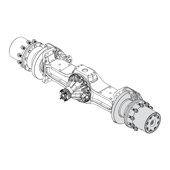
FIELD MAINTENANCE MANUAL
STE - R013R -
Ed 08/07
EXTREMITE DE ROUE / WHEEL END ASSEMBLY
Indices/Rev
Date
Description
B
07-Aug-2007
Remise à jour du manuel / Updating of Manual
A
01-Jun-2006
New Release
Publicité
Table des Matières

Manuels Connexes pour AxleTech STE-R013R


Sommaire des Matières pour AxleTech STE-R013R
- Page 1 AxleTech Internationnal S.A.S. 4 rue Jean Servanton B.P. 656 42042 Saint Etienne CEDEX 1 Tel :33 (0)4.77 92 88 00 Fax:33 (0)4.77 74 88 98 MANUEL DE MAINTENANCE FIELD MAINTENANCE MANUAL STE - R013R - Ed 08/07 EXTREMITE DE ROUE / WHEEL END ASSEMBLY...
- Page 2 Sommaire / Table of contents Section 1 Roulements - Joints / Bearings -Seals........page/sheet 4 Etancheïté des faces / Sealing surfaces ........page/sheet 6 Visserie / Fastening..............page/sheet 8 Lubrification / Lubrication ............page/sheet 10 Vue éclatée / Exploded view ............page/sheet 12 Section 2 Démontage / Disassembly ............page/sheet 15 Section 3...
- Page 3 Notes R013R-08/07...
-
Page 4: Remarques Concernant L'entretien
REMARQUES CONCERNANT L'ENTRETIEN Ce Manuel de Maintenance décrit les procédures de réparation et d'entretien correctes pour les extrémités de roue Axletech. Les informations contenues dans ce manuel étaient d'actualité au moment de l'impression et peuvent être modifiées sans préavis ni engagement. - Page 5 Section 1 Introduction I - ROULEMENT A ROULEAUX CONIQUES Si la propreté des pièces au montage et la lubrification sont respectées, il est rare au démontage de trouver des roulements en mauvais état. Dans la mesure du possible on évitera donc de les démonter, car on risque avec l’extracteur de détériorer la cage ou même la cuvette si on démonte par chocs.
- Page 6 Section 1 Preliminary I - TAPERED ROLLER BEARINGS If the parts are clean and properly lubricated, it is rare to find damaged bearings during removal. Therefore,one must avoid removing them because they may be damaged by the puller. - Case of removing of a bearing - Abnormal wear of the bearing surface.
- Page 7 Section 1 Introduction III - ETANCHEÎTÉ DES FACES. - Application du SILICOMET Caractéristiques du produit. - Couleur : Incolore - Odeur : Acétique non toxique - Température : résistance de - 50°C à + 200°C - A UTILISER AVEC PRÉCAUTIONS : éviter tout contact avec la peau et les yeux. Ne pas fumer. Démontage - Démonter les assemblages, en cas de blocage décoller les pièces par choc pour rompre le film.
- Page 8 Section 1 Preliminary III- SEALING OF MOUNTING SURFACES - Application of SILICOMET Product characteristics - Colour : Coulour less - Smell : acetic non toxic - Temperature : resistance - 50°C to + 200°C - TO BE USED WITH CARE : avoid any contact with eyes and skin and do not smoke. Disassembly - Disassemble the units : In the event of sticking, tap the parts to break the film.
- Page 9 Section 1 Introduction IV - VISSERIE. Les vis non microcapsulées ou réutilisées après démontage seront montées au LOCTITE frein filet SR 242. Caractéristique du produit - Couleur : bleu clair - Température : résistance de – 55°C à + 150°C - A UTILISER AVEC PRECAUTIONS : Eviter tout contact avec la peau et les yeux.
- Page 10 Section 1 Preliminary IV - FASTENING Screws without adhesive drive lock or re-use after removing used LOCTITE Frein filet SR 242. Product characteristics - Colour : pale blue - Temperature : resistance - 55°C to + 150°C - TO BE USED WITH CARE : avoid any contact with eyes and skin and do not smoke. Disassembly - Disassemble the units, in case of lock, heat the screws.
- Page 11 Section 1 Introduction LUBRIFICATION EXTREMITE ROUE QUALITÉ D’HUILE Le service imposé au matériel nécessite une huile 80 W 90 de la classification API GL 5 et homologuée selon la spécification militaire MIL L 2105 D. Les huiles utilisées doivent être compatibles entre elles et avec les graisses des sous-ensembles, et ne pas attaquer les élastomères.
- Page 12 Section 1 Preliminary WHEEL END LUBRICATION LUBRICANT QUALITY Due to the heavy duty operation, only a multigrade lubricant 80 W 90 with service level API GL5 and approved as meeting US MIL L 2105 D specification is recommended All lubricants used must be compatible between them and to seals materials. Avoid mixing two different oil types, even if from the same trade name.
- Page 13 Section 1 Vue éclatée / Exploded view - 12 - R013R-08/07...
- Page 14 Section 1 Vue éclatée / Exploded view Fusée ..........Spindle ..........Vis Chc M14x150 ......Screw ..........Piste de joint ........Seal race ........... Disque de frein ........Rotor ..........Goujon de roue M 22x150 ....Wheel stud ........Moyeu de roue ........Wheel hub ......... Joint d’étancheité...
- Page 15 Notes - 14 - R013R-08/07...
- Page 16 Section 2 Démontage / Disassembly AVERTISSEMENT WARNING Afin d’éviter de se blesser et d’endommager les To avoid serious personal injury and damage to composants, faites attention lors de l’utilisation components, take care when using lifting devices des dispositifs de levage pendant les interventions. during service and maintenance procedures.
- Page 17 Section 2 Démontage / Disassembly Débloquer et déposer l'écrou (24). Déposer la vis (26) et son joint cuivre (25). Déposer la vis de réglage (23). Unlock and remove nut (24). Remove screw (26) and copper seal (25). Remove adjusting screw (23). Déposer le couvercle (22).
- Page 18 Section 2 Démontage / Disassembly CAUTION ATTENTION The outer bearing cone will be loose as you pass Le cone du roulement sera libre si vous Dépassez it over the end of the spindle. Hold the cone l’extrémité de la fusée. Tenir le cone avec précaution securely to avoid dropping it and damaging afin d’éviter de le faire tomber et de l’endommager.
- Page 19 Section 2 Démontage / Disassembly CAUTION ATTENTION Do not damage the hub oil seal bore surface in Ne pas endommager l’alésage du joint situé dans le the wheel hub. Damage to this surface will result moyeu. Les dommages sur cette surface in oil leakage after assembly.
- Page 20 Section 2 Démontage / Disassembly Déposer le frein (30). Remove the disc brake (30). Déposer l’ensemble moyeu-disque. Remove the hub and rotor. Installer des vis M10 pour décoller le moyeu du disque. Déposer le moyeu assemblé. Fit the extraction screws (M10) to release the hub. Remove the whell hub.
- Page 21 Section 2 Démontage / Disassembly Retourner le moyeu (8). Extraire le joint (6), la cuvette et le cône du roulement (7) du moyeu. Return the hub (8). Remove seal (6), bearing cup and bearing (7) from wheel hub. WARNING AVERTISSEMENT Use a rubber mallet for disassembly and assembly Utilisez un maillet en caoutchouc .
- Page 22 Section 2 Démontage / Disassembly Déposer les vis de fixation (2) de la fusée (1). Déposer la fusée (1). Remove spindle screws (2). Remove spindle (1). R013R-08/07 21 -...
- Page 23 Section 3 Montage / Assembly AVERTISSEMENT WARNING Afin d’éviter de se blesser et d’endommager les To avoid serious personal injury and damage to composants, faites attention lors de l’utilisation components, take care when using lifting devices des dispositifs de levage pendant les during service and maintenance procedures.
- Page 24 Section 3 Montage / Assembly Mettre en place la fusée (1). Monter les vis de fixation (2) à la loctite 242 et Serrer à 198 Nm. Place spindle (1). Mount screws (2) with Loctite 242 and tighten it to 146 lb-ft (198Nm). Déposer un filet de LOCTITE 549 sur la fusée et monter la piste de joint (3) après avoir chauffé...
- Page 25 Section 3 Montage / Assembly Mettre en place la cuvette de roulement (9) dans le moyeu. Utiliser le cimblot 5046. Place bearing cup (9) onto wheel hub. Use cup driver # 5046. Remplir de graisse LGMT 2 de SKF ou Multi EP 2 de Total. Grease SKF LGMT 2 or Total Multi EP 2.
- Page 26 Section 3 Montage / Assembly Monter le moyeu assemblé sur la fusée. Le maintenir en place. With a lifting strap, fit the hub assembly onto the spindle. Hold the spindle in position. Monter le cône du roulement (9) sur le porte couronne (10) après l'avoir chauffé...
- Page 27 Section 3 Montage / Assembly Serrer l’ecrou (12) à 400 Nm. Utiliser la clé 5231. Fit spindle nut (12), tighten him to 295 lb-ft (400 Nm). Use spanner # 5231. WARNING AVERTISSEMENT Use a rubber mallet for disassembly and assembly Utilisez un maillet en caoutchouc .
- Page 28 Section 3 Montage / Assembly Engager la languette de la rondelle frein (11) dans l’encoche de l’écrou (12). Si la languette n’est pas alignée avec l’encoche de l’écrou, ajuster en devissant l’écrou. Inster the tongue of lock washer (11) into groove of nut (12).
- Page 29 Section 3 Montage / Assembly Mettre en place la vis du planétaire (17). Utiliser la Loctite 242 - serrer à 194 Nm.. Utiliser un jet en bronze pour immobiliser le planétaire. Maintain the sun gear with jet extractor of bronze. Apply Loctite 242 to the threads of the screw (17).
- Page 30 Section 3 Montage / Assembly Graisser et monter le joint torique (21) sur le couvercle (22). Grease and fit the O’ring (21) on the cover (22). Mettre en place le couvercle (22), monter les rondelles (27) avec les vis (28) a la loctite 242, les serrer à 60 Nm. Position cover (22), fit the washers (27) and the screws (28) with loctite 242, tighten them to 44 lb-ft (60 Nm).
- Page 31 Section 3 Montage / Assembly Monter le contre-écrou (24) de la vis de règlage. Etancher à la Loctite 242. Fit check nut (24) of adjusting screw. Seal with Loctite 242. Serrer le contre-écrou (24) à 200 Nm. Tighten check nut (24) to 148 lb-ft (200 Nm). Refaire le niveau - voir section 1.
- Page 32 Section 3 Montage / Assembly Positionner l’étrier de frein(30) sur le pont. Mettre les rondelles (34), Mettre de la Loctite 242 sur les vis (31) (35) et bloquer à 298 Nm (Vis M16x150). Install the brake disc (30), place the washer (34). Use Loctite 242 and tighten screws (31) (35) to 220 lb-ft (298 Nm).
-
Page 33: Outillage Reducteurs De Roue
OUTILLAGE REDUCTEURS DE ROUE TOOLS FOR PLANETARY HUB REDUCERS... -
Page 34: Planche Annexe
PLANCHE ANNEXE ENCLOSURE SHEET N°plan pour N°plan pour N°plan pour N°plan pour N°plan pour N° manuel N°plan pour cimblot emmanch emmanch emmanch guide maintenance écrou fusée extraction cuvette bague etan, joint CTI manchon CTI Drawing & part Drawing & Drawing & part Drawing &... - Page 35 Suite 400 AxleTech, International France AxleTech do Brasil Sistemas Automotivos Ltda. 3001 West Big Beaver Road 4, Rue Jean Servanton Avendia Joao Batista, 830 Troy, Michigan 48084 Boite Postale 656 Centro-Osasco-SP U.S.A. 42042 Saint Etienne Cedex 1 06097095 Brasil Toll Free: 877-877-9717...