Agilent Technologies TwisTorr 304 FS AG Notice De Mode D'emploi
Masquer les pouces
Voir aussi pour TwisTorr 304 FS AG:
- Mode d'emploi (304 pages) ,
- Mode d'emploi (178 pages)
Publicité
Liens rapides
Manuale di istruzioni
Bedienungshandbuch
Notice de mode d'emploi
Manual de istrucciones
Manual de istruções
Bedrijfshandleiding
Istrukstionsbog
Bruksanvisning
87-901-029-01 (E)
02/2019
TwisTorr 304 FS AG
Rack Controller
Models
X3506-64002, X3506-64003
Instruksjon manual
Ohjekäsikirja
Felhasználói kézikönyv
Podrecznik instrukcji
Návod k použití
Návod na obsluhu
Priročnik za navodila
User Manual
Publicité
Chapitres

Manuels Connexes pour Agilent Technologies TwisTorr 304 FS AG


Sommaire des Matières pour Agilent Technologies TwisTorr 304 FS AG
- Page 1 TwisTorr 304 FS AG Rack Controller Models X3506-64002, X3506-64003 Manuale di istruzioni Instruksjon manual Bedienungshandbuch Ohjekäsikirja Notice de mode d’emploi Felhasználói kézikönyv Manual de istrucciones Podrecznik instrukcji Manual de istruções Návod k použití Bedrijfshandleiding Návod na obsluhu Istrukstionsbog Priročnik za navodila...
- Page 2 “Restricted computer software” as proceed beyond a WARNING notice defined in FAR 52.227-19 (June 1987) until the indicated conditions are or any equivalent agency regulation or fully understood and met. TwisTorr 304 FS AG Rack Controller User Manual / 87-901-029-01 (E)
- Page 3 TwisTorr 304 FS AG Rack Controller TwisTorr 304 FS AG Rack Controller TwisTorr 304 FS AG Rack Controller User Manual / 87-901-029-01 (E) 3/301...
- Page 4 TwisTorr 304 FS AG Rack Controller 4/301 TwisTorr 304 FS AG Rack Controller User Manual / 87-901-029-01 (E)
-
Page 5: Table Des Matières
Installazione Procedure di uso Manutenzione 23 Smaltimento Messaggi di errore 25 Gebrauchsanleitung 27 Allgemeines 28 Lagerung Vor der Installation 30 Installation 31 Gebrauch Bedienung 35 Wartung Entsorgung 36 5/301 TwisTorr 304 FS AG Rack Controller User Manual / 87-901-029-01 (E) - Page 6 Messages d'erreur 49 Manual de istrucciones 51 Información general 52 Almacenamiento Preparación para la instalación 54 Instalación 55 Procedimientos de uso 59 Mantenimiento 59 Eliminación 60 Mensajes de error 61 6/301 TwisTorr 304 FS AG Rack Controller User Manual / 87-901-029-01 (E)
- Page 7 Eliminação 72 Mensagens de erro 73 Bedrijfshandleiding 75 Algemene informatie Opslag Voorbereiding voor installatie Installatie 79 Gebruik Gebruiksprocedures 83 Onderhoud 83 Afvalverwerking 84 Foutmeldingen 85 Istruktionsbog Generel Information 88 7/301 TwisTorr 304 FS AG Rack Controller User Manual / 87-901-029-01 (E)
- Page 8 Allmän Information 100 Förvaring Förberedelser för installation 102 Installation 103 Användning 104 Instruktioner för bruk Underhåll Bortskaffning Felmeddelanden 109 Instruksjon Manual 111 Generell informasjon 112 Lagring Forberede installasjonen 114 8/301 TwisTorr 304 FS AG Rack Controller User Manual / 87-901-029-01 (E)
- Page 9 Varastointi 125 Valmistelut asennusta varten 126 Asennus Käyttö Käyttötoimenpiteet 131 Huolto Hävittäminen Vianetsintä 133 11 Felhasználói Kézikönyv 135 Általános információk Tárolás A telepítésre való előkészítés Telepítés 139 Használat 140 TwisTorr 304 FS AG Rack Controller User Manual / 87-901-029-01 (E) 9/301...
- Page 10 Uzytkowanie Procedure uzytkowania 155 Konserwacja Przetworstwo odpadow 156 Bledne informacje 157 13 Návod k Použití Všeobecné informace Uskladnění 161 Příprava k instalaci 162 Instalace Použití Používané procedury Údržba 10/301 TwisTorr 304 FS AG Rack Controller User Manual / 87-901-029-01 (E)
- Page 11 Oznamy vád 181 15 Priročnik za Navodila Splošne informacije 184 Skladiščenje185 Priprava za montažo 186 Montaža Uporaba Postopki uporabe Vzdrževanje 191 Odlaganje opadkov 192 Obvestilo o napaki 193 TwisTorr 304 FS AG Rack Controller User Manual / 87-901-029-01 (E) 11/301...
- Page 12 R1 – R2 Output Diagrams Programmable Analog Output Diagrams 222 J2 – Serial Connector Letter Protocol Description 231 Examples How to Use by Front Panel 249 Use 255 12/301 TwisTorr 304 FS AG Rack Controller User Manual / 87-901-029-01 (E)
- Page 13 Contents Programming How to Use by Remote I/0 276 How to Use in Serial Mode 276 Profibus Option 278 Error Messages 292 Orderable Parts 295 TwisTorr 304 FS AG Rack Controller User Manual / 87-901-029-01 (E) 13/301...
- Page 14 Contents 14/301 TwisTorr 304 FS AG Rack Controller User Manual / 87-901-029-01 (E)
-
Page 15: Istruzioni Per L'uso
TwisTorr 304 FS AG Rack Controller User Manual Istruzioni per l’uso Informazioni Generali 16 Immagazzinamento Preparazione per l’installazione 18 Installazione Comandi, Indicatori e Connettori 21 Descrizione pannello frontale Procedure di uso 21 Accensione del Controller Avvio della Pompa 23 Arresto della Pompa... -
Page 16: Informazioni Generali
Impostazione automatica tensione di ingresso. Nei paragrafi seguenti sono riportate tutte le informazioni necessarie a garantire la sicurezza dell'operatore durante l'utilizzo dell'apparecchiatura. Informazioni dettagliate sono fornite nell'appendice "Technical Information". 16/301 TwisTorr 304 FS AG Rack Controller User Manual / 87-901-029-01 (E) -
Page 17: Immagazzinamento
Durante il trasporto e l’immagazzinamento dei controller devono essere soddisfatte le seguenti condizioni ambientali: temperatura: da -20 °C a +70 °C umidità relativa: 0 – 95 % (non condensante) TwisTorr 304 FS AG Rack Controller User Manual / 87-901-029-01 (E) 17/301... -
Page 18: Preparazione Per L'installazione
Non disperdere l'imballo nell'ambiente. Il materiale è completamente riciclabile e risponde alla direttiva CEE 85/399 per la tutela dell'ambiente. Figura 1 Imballo dei controller 18/301 TwisTorr 304 FS AG Rack Controller User Manual / 87-901-029-01 (E) -
Page 19: Installazione
5 °C a +45 °C; umidità relativa: 0 – 95 % (non condensante). Per gli altri collegamenti e I'installazione degli accessori opzionali, vedere la sezione "Technical Information". TwisTorr 304 FS AG Rack Controller User Manual / 87-901-029-01 (E) 19/301... -
Page 20: Uso
Il connettore di richiusura J1 deve essere lasciato collegato con il suo ponticello NOTA se non viene effettuato alcun collegamento esterno. La pompa di pre-vuoto e la pompa TwisTorr 304 FS possono essere accese contemporaneamente. 20/301 TwisTorr 304 FS AG Rack Controller User Manual / 87-901-029-01 (E) -
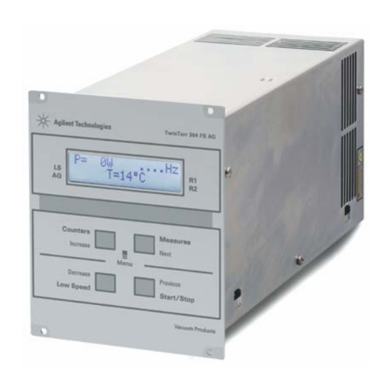
Page 21: Comandi, Indicatori E Connettori
Display alfanumerico a cristalli liquidi: matrice di punti, 2 linee x 16 caratteri. TwisTorr 304 FS AG Rack Controller User Manual / 87-901-029-01 (E) 21/301... - Page 22 Modulo di ingresso alimentazione controller che comprende i fusibili, la presa di alimentazione ed il filtro ENC. Switch a rotazione per impostare l’indirizzo del Profibus. Profibus (opzionale). Connettore seriale per controllo da remoto. Pompa. 22/301 TwisTorr 304 FS AG Rack Controller User Manual / 87-901-029-01 (E)
-
Page 23: Procedure Di Uso
Per arrestare la pompa occorre premere il pulsante STOP del pannello frontale. Manutenzione I controller della serie TwisTorr 304 FS AG Rack non richiedono alcuna manutenzione. Qualsiasi intervento deve essere eseguito da personale autorizzato. In caso di guasto è possibile usufruire del servizio di riparazione Agilent o del "Agilent advanced exchange... -
Page 24: Smaltimento
Per maggiori informazioni riferirsi i i a: http://www.agilent.com/environment/product/index.shtml 24/301 TwisTorr 304 FS AG Rack Controller User Manual / 87-901-029-01 (E) -
Page 25: Messaggi Di Errore
Premere Oppure. due volte il pulsante START La temperatura del radiatore del per riavviare la pompa. controller è superiore a 60 °C. TwisTorr 304 FS AG Rack Controller User Manual / 87-901-029-01 (E) 25/301... - Page 26 Se il messaggio si un segnale spurio. ripresenta rivolgersi in Agilent per la manutenzione. POWER FAIL Guasto nella sezione di Rivolgersi alla Agilent per alimentazione della pompa, del Manutenzione. controller. 26/301 TwisTorr 304 FS AG Rack Controller User Manual / 87-901-029-01 (E)
-
Page 27: Gebrauchsanleitung
TwisTorr 304 FS AG Rack Controller User Manual Gebrauchsanleitung Allgemeines Lagerung Vor der Installation Installation Gebrauch Steuerungen, Anzeigen und Verbinder des Controllers 32 Fronttafel der Controller Bedienung Einschalten des Controllers 35 Pumpenstart 35 Pumpenstopp 35 Wartung Entsorgung Fehlermeldungen 37 Übersetzung der Originalanleitungen... -
Page 28: Allgemeines
In den folgenden Abschnitten sind alle erforderlichen Informationen für die Sicherheit des Bedieners bei der Anwendung des Geräts aufgeführt. Detaillierte technische Informationen sind im Anhang "Technical Information" enthalten. 28/301 TwisTorr 304 FS AG Rack Controller User Manual / 87-901-029-01 (E) -
Page 29: Lagerung
Beim Transport und bei der Lagerung der Controller müssen folgende klimatische Verhältnisse eingehalten werden: Temperatur: von -20 °C bis +70 °C Relative Luftfeuchtigkeit: 0 – 95 % (nicht kondensierend) TwisTorr 304 FS AG Rack Controller User Manual / 87-901-029-01 (E) 29/301... -
Page 30: Vor Der Installation
Beim Auspacken vorsichtig vorgehen, damit der Controller nicht fällt oder Stößen ausgesetzt wird. Das Verpackungsmaterial muß korrekt entsorgt werden. Es ist vollständig recyclebar und entspricht der EG-Richtlinie 85/399 für Umweltschutz. Abbildung 1 Verpackung der Controller 30/301 TwisTorr 304 FS AG Rack Controller User Manual / 87-901-029-01 (E) -
Page 31: Installation
Gasen ausgesetzt sind und in denen Explosions- und erhöhte Brandgefahr besteht. Beim Betrieb müssen folgende Umgebungsbedingungen eingehalten werden: Temperatur: von +5 °C bis +45 °C Relative Luftfeuchtigkeit: 0 – 95 % (nicht kondensierend). TwisTorr 304 FS AG Rack Controller User Manual / 87-901-029-01 (E) 31/301... -
Page 32: Gebrauch
Schließflansch abgedeckt ist. Der Wiederverschließ-Verbinder J1 muß mit seiner Brücke angeschlossen HINWEIS bleiben, wenn kein externer Anschluß erfolgt. Die Vorvakuumpumpe und die TwisTorr 304 FS Pumpe können gleichzeitig eingeschaltet werden. 32/301 TwisTorr 304 FS AG Rack Controller User Manual / 87-901-029-01 (E) -
Page 33: Steuerungen, Anzeigen Und Verbinder Des Controllers
Drücken stoppt die Pumpe. Bei automatischem Pumpenstopp durch Störung muß diese Taste ein erstes Mal zur Controller-Rücksetzung und dann ein zweites Mal zum Neustarten der Pumpe gedrückt werden. Alphanumerisches Flüssigkristall-Display: Punkt-matrix, 2 Zeilen mit 16 Stellen. TwisTorr 304 FS AG Rack Controller User Manual / 87-901-029-01 (E) 33/301... - Page 34 Stromausgangsstecker (24 V= für Pumpenkühlventilator, Vent Valve und Messinstrument). Netzeingangsmodul des Controllers bestehend aus Netzsicherungen, Netzstecker und EMC Filter. Drehschalter zum Setzen der Profibus Adresse. Profibus (Option). Serieller Stecker zur Fernsteuerung. Pumpenstecker. 34/301 TwisTorr 304 FS AG Rack Controller User Manual / 87-901-029-01 (E)
-
Page 35: Bedienung
Zum Stoppen der Pumpe muß die STOP-Taste an der Fronttafel gedrückt werden. Wartung Die Controller der Serie TwisTorr 304 FS AG Rack sind wartungsfrei. Eventuell erforderliche Eingriffe müssen von dazu befugtem Fachpersonal ausgeführt werden. Bei einem Defekt kann der Agilent- Reparaturdienst bzw. -
Page 36: Entsorgung
Endabnehmer sollte daher den Lieferanten des Geräts - d.h. die Muttergesellschaft oder den Wiederverkäufer - kontaktieren, um den Entsorgungsprozess zu starten, nachdem er die Verkaufsbedingungen geprüft hat. Weitere Informationen finden Sie unter: http://www.agilent.com/environment/product/index.shtml 36/301 TwisTorr 304 FS AG Rack Controller User Manual / 87-901-029-01 (E) -
Page 37: Fehlermeldungen
Warten bis die Temperatur OVERTEMP. 70 °C überschritten. unter den Schwellenwert gesunken ist. Die Pumpe Oder durch zweimalige Die Temperatur des Betätigung der START-Taste Kontrollerkühlkörpers ist über neustarten. 60 °C. TwisTorr 304 FS AG Rack Controller User Manual / 87-901-029-01 (E) 37/301... - Page 38 Betätigung der START-Taste ein falsches Signal erhalten neustar-ten. Erscheint die Meldung wieder sollte der Agilent-Wartungs-dienst gerufen werden. POWER FAIL Defekt im Pumpenstromkreis des Agilent für Wartung Controllers. kontaktieren. 38/301 TwisTorr 304 FS AG Rack Controller User Manual / 87-901-029-01 (E)
-
Page 39: Mode D'emploi
TwisTorr 304 FS AG Rack Controller User Manual Mode d’emploi Indications generales 40 Emmagasinage Preparation pour l‘installation 42 Installation Utilisation Commandes, Indicateurs et Connecteurs 45 Description du Tableau avant Procedures d'utilisation Allumage du Contrôleur 47 Mise en marche de la Pompe Arrêt de la Pompe 47... -
Page 40: Indications Generales
Les paragraphes suivants donnent toutes les indications nécessaires à garantir la sécurité de l'opérateur pendant l'utilisation de l'appareillage. Des renseignements plus détaillés se trouvent dans l'appendice "Technical Information". 40/301 TwisTorr 304 FS AG Rack Controller User Manual / 87-901-029-01 (E) -
Page 41: Cette Notice Utilise Les Signes Conventionnels Suivants
Pendant le transport et l'emmagasinage des contrôleurs, il faudra veiller à respecter les conditions environnementales suivantes: température: de - 20 °C à + 70 °C humidité relative: de 0% à 95 % (non condensante). TwisTorr 304 FS AG Rack Controller User Manual / 87-901-029-01 (E) 41/301... -
Page 42: Preparation Pour L'installation
Ne pas jeter l'emballage dans la nature. Le matériel est entièrement recyclable et il est conforme aux directives CEE 85/399 en matière de protection de l'environnement. Figure 1 Emballage du Contrôleur 42/301 TwisTorr 304 FS AG Rack Controller User Manual / 87-901-029-01 (E) -
Page 43: Installation
humidité relative: de 0 % à 95 % (non condensante). Pour les autres connexions et pour l'installation des accessoires en option, voir la section "Technical Information". TwisTorr 304 FS AG Rack Controller User Manual / 87-901-029-01 (E) 43/301... -
Page 44: Utilisation
Laisser le connecteur de réenclenchement J1 connecté à sa barrette s'il n'est NOTE procédé à aucune connexion extérieure. La pompe à pré-vide et la pompe TwisTorr 304 FS peuvent être mises en marche simultanément. 44/301 TwisTorr 304 FS AG Rack Controller User Manual / 87-901-029-01 (E) -
Page 45: Commandes, Indicateurs Et Connecteurs
à zéro du contrôleur et une deuxième fois pour remettre la pompe en marche. Ecran alphanumérique à cristaux liquides: matrice de points, 2 lignes x 16 caractères. TwisTorr 304 FS AG Rack Controller User Manual / 87-901-029-01 (E) 45/301... - Page 46 Module d’entrée alimentation contrôleur qui comprend les fusibles, la prise d’alimentation et le filtre ENC. Interrupteur à rotation pour établir l’adresse du Profibus. Profibus (facultatif). Connecteur sériel pour contrôle à distance Connecteur pompe. 46/301 TwisTorr 304 FS AG Rack Controller User Manual / 87-901-029-01 (E)
-
Page 47: Procedures D'utilisation
Pour arrêter la pompe, presser l'interrupteur STOP du tableau frontal. Entretien Les contrôleurs de la série TwisTorr 304 FS AG Rack n'exigent aucun entretien. Toute opération doit être effectuée par un personnel agréé. En cas de panne, il est possible de s'adresser au Service de réparation Agilent ou bien au "Agilent advance exchange service"... -
Page 48: Mise Au Rebut
œuvre le processus de collecte et mise au rebut. Pour en savoir plus, consulter : http://www.agilent.com/environment/product/index.shtml 48/301 TwisTorr 304 FS AG Rack Controller User Manual / 87-901-029-01 (E) -
Page 49: Messages D'erreur
Presser deux fois Ou bien l'interrupteur START pour La température du radiateur du remettre la pompe en contrôleur est supérieure à 60 °C. marche. TwisTorr 304 FS AG Rack Controller User Manual / 87-901-029-01 (E) 49/301... - Page 50 Si le message se présente à nouveau, s'adresser à Agilent pour l'entretien. POWER FAIL Panne dans la section S’adresser à Agilent pour d’alimentation de la pompe, du Maintenance. contrôleur. 50/301 TwisTorr 304 FS AG Rack Controller User Manual / 87-901-029-01 (E)
-
Page 51: Manual De Istrucciones
TwisTorr 304 FS AG Rack Controller User Manual Manual de istrucciones Información general Almacenamiento 53 Preparación para la instalación 54 Instalación Mandos, Indicadores y Conectores Descripción del panel frontal 57 Procedimientos de uso Encendido del controler59 Puesta en marcha de la Bomba 59... -
Page 52: Información General
En los apartados siguientes se facilita toda la información necesaria para garantizar la seguridad del operador durante el uso del equipo. Una información más detallada se facilita en el Suplemento "Technical Information". 52/301 TwisTorr 304 FS AG Rack Controller User Manual / 87-901-029-01 (E) -
Page 53: Almacenamiento
Durante el transporte y el almacenamiento de los controlers se deberá cumplir con las condiciones ambientales siguientes: temperatura: de -20 °C a +70 °C humedad relativa: 0 – 95 % (no condensadora) TwisTorr 304 FS AG Rack Controller User Manual / 87-901-029-01 (E) 53/301... -
Page 54: Preparación Para La Instalación
El material es totalmente reciclable y cumple con la directiva CEE 85/399 para la preservación del medio ambiente. Figura 1 Embalaje de los Controlers 54/301 TwisTorr 304 FS AG Rack Controller User Manual / 87-901-029-01 (E) -
Page 55: Instalación
+5 °C a +45 °C humedad relativa: 0 – 95 % (no condensadora). Para otras conexiones y la instalación de los accesorios opcionales, véase la sección “Technical Information”. TwisTorr 304 FS AG Rack Controller User Manual / 87-901-029-01 (E) 55/301... -
Page 56: Uso
El conector di cierre J1 ha de dejarse conectado con su conector puente NOTA si no se efectúa ninguna conexión exterior. La bomba pre-vacío y la bomba TwisTorr 304 FS pueden encenderse simultáneamente. 56/301 TwisTorr 304 FS AG Rack Controller User Manual / 87-901-029-01 (E) -
Page 57: Mandos, Indicadores Y Conectores
Display alfanumérico de cristales líquidos: matriz de puntos, 2 líneas x 16 caracteres. TwisTorr 304 FS AG Rack Controller User Manual / 87-901-029-01 (E) 57/301... - Page 58 Módulo de entrada alimentación controler con fusibles, toma de alimentación y filtro ENC. Conmutador de rotación para configurar la dirección del Profibus. Profibus (opcional). Conector serial para control remoto. Conector bomba. 58/301 TwisTorr 304 FS AG Rack Controller User Manual / 87-901-029-01 (E)
-
Page 59: Procedimientos De Uso
Para detener la bomba hay que apretar el pulsador STOP del panel frontal. Mantenimiento Los controlers de la serie TwisTorr 304 FS AG Rack no necesitan ningún mantenimiento. Cualquier operación ha de ser efectuada por personal autorizado. En caso de avería es posible utilizar el servicio de reparación Agilent o del “Agilent advance exchange service”, que... -
Page 60: Eliminación
Para obtener más información, con n n s s s ulte: http://www.agilent.com/environment/product/index.shtml 60/301 TwisTorr 304 FS AG Rack Controller User Manual / 87-901-029-01 (E) -
Page 61: Mensajes De Error
Apretar dos veces el O bien pulsador START para volver La temperatura del radiador del a poner en marcha la bomba. controler es superior a 60 °C. TwisTorr 304 FS AG Rack Controller User Manual / 87-901-029-01 (E) 61/301... - Page 62 Agilent para el mantenimiento. POWER FAIL Avería en la sección de Ponerse en contacto con alimentación de la bomba, del Agilent para el controler. Mantenimiento. 62/301 TwisTorr 304 FS AG Rack Controller User Manual / 87-901-029-01 (E)
-
Page 63: Manual De Istruções
TwisTorr 304 FS AG Rack Controller User Manual Manual de Istruções Informações gerais Armazenagem Preparação para a instalação Instalação Utilização Comandos, Indicadores e Conectores Descrição painel frontal Procedimentos de uso 71 Acendimento do Controller 71 Activação da bomba Paragem da bomba 71 Manutenção... -
Page 64: Informações Gerais
às normas nacionais específicas. Os controllers da série TwisTorr 304 FS AG Rack são conversores de frequência, controlados por um microprocessador, realizados com componentes em estado sólido e com capacidade de autodiagnóstico e autoprotecção. -
Page 65: Armazenagem
Durante o transporte e a armazenagem dos controllers, devem ser satisfeitas as seguintes condições ambientais: temperatura: de -20 °C a + 70 °C humidade relativa: 0 – 95 % (não condensante) TwisTorr 304 FS AG Rack Controller User Manual / 87-901-029-01 (E) 65/301... -
Page 66: Preparação Para A Instalação
O material é completamente reciclável e responde à directriz CEE 85/399 para a protecção do meio ambiente. Figura 1 Embalagem dos controllers 66/301 TwisTorr 304 FS AG Rack Controller User Manual / 87-901-029-01 (E) -
Page 67: Instalação
+5 °C a +45 °C humidade relativa: 0 – 95 % (não condensante). Para as outras ligações e a instalação dos acessórios opcionais, ver a secção "Technical Information". TwisTorr 304 FS AG Rack Controller User Manual / 87-901-029-01 (E) 67/301... -
Page 68: Utilização
O conector de fecho J1 deve permanecer ligado à sua ponte se não é efectuada NOTA nenhuma ligação externa. A bomba de pré-vácuo e a bomba TwisTorr 304 FS podem ser ligadas simultaneamente. 68/301 TwisTorr 304 FS AG Rack Controller User Manual / 87-901-029-01 (E) -
Page 69: Comandos, Indicadores E Conectores
Display alfanumérico com cristais líquidos: matriz de pontos 2 linhas x 16 caracteres. TwisTorr 304 FS AG Rack Controller User Manual / 87-901-029-01 (E) 69/301... - Page 70 Modulo de entrada alimentação controller que compreende os fusíveis, a tomada de alimentação e o filtro ENC. Switch em rotação para impostar o endereço do Profibus. Profibus (opcional). Conector serial para controle de remoto. Conector bomba. 70/301 TwisTorr 304 FS AG Rack Controller User Manual / 87-901-029-01 (E)
-
Page 71: Procedimentos De Uso
Para parar a bomba, é necessário premer o botão STOP do painel frontal. Manutenção Os controllers da série TwisTorr 304 FS AG Rack não requerem qualquer manutenção. Todas as operações devem ser efectuadas por pessoal autorizado. Em caso de defeito é possível utilizar o serviço de reparação Agilent ou o "Agilent advanced exchange service", que permite obter um... -
Page 72: Eliminação
Para mais informações consulte: http://www.agilent.com/environment/product/index.shtml 72/301 TwisTorr 304 FS AG Rack Controller User Manual / 87-901-029-01 (E) -
Page 73: Mensagens De Erro
70 ºC. estabelecido. Premer duas vezes o botão START para reactivar a bomba. A temperatura do radiador do controller é superior a 60 °C. TwisTorr 304 FS AG Rack Controller User Manual / 87-901-029-01 (E) 73/301... - Page 74 Se a mensagem se reapresentar, dirigir-se à Agilent para a manutenção. POWER FAIL Avaria na seção de alimentação da Dirigir-se a Agilent para bomba, do controller. Manutenção. 74/301 TwisTorr 304 FS AG Rack Controller User Manual / 87-901-029-01 (E)
-
Page 75: Bedrijfshandleiding
TwisTorr 304 FS AG Rack Controller User Manual Bedrijfshandleiding Algemene informatie 76 Opslag 77 Voorbereiding voor installatie Installatie Gebruik Bedieningsorganen, Controlelampjes en Connectoren van 81 Beschrijving frontpaneel Gebruiksprocedures Inschakelen van de controller Starten van de pomp Stoppen van de pomp 83... -
Page 76: Algemene Informatie
In de volgende paragrafen is alle informatie vermeld om de veiligheid van de operator tijdens het gebruik van de apparatuur te verzekeren. Gedetailleerde informatie is te vinden in de bijlage "Technical information". 76/301 TwisTorr 304 FS AG Rack Controller User Manual / 87-901-029-01 (E) -
Page 77: Opslag
Tijdens het transport en de opslag van de controllers moeten de volgende omgevingscondities aanwezig zijn: temperatuur: van -20 °C tot +70 °C relatieve vochtigheid: 0 – 95 % (niet condenserend) TwisTorr 304 FS AG Rack Controller User Manual / 87-901-029-01 (E) 77/301... -
Page 78: Voorbereiding Voor Installatie
Laat de verpakking niet ergens buiten achter. Het verpakkingsmateriaal is volledig recyclebaar en voldoet aan de EEG milieurichtlijn 85/399. Figuur 1 Verpakking van de controllers 78/301 TwisTorr 304 FS AG Rack Controller User Manual / 87-901-029-01 (E) -
Page 79: Installatie
+5 °C tot +45 °C relatieve vochtigheid: 0 – 95 % (niet condenserend). Voor de overige aansluitingen en de installatie van de accessoires wordt verwezen naar het hoofdstuk "Technical Information". TwisTorr 304 FS AG Rack Controller User Manual / 87-901-029-01 (E) 79/301... -
Page 80: Gebruik
De connector J1 moet met zijn jumper aangesloten blijven als geen externe OPMERKING aansluiting tot stand wordt gebracht. De pre-vacuümpomp en de TwisTorr 304 FS pomp mogen beide gelijktijdig ingeschakeld zijn. 80/301 TwisTorr 304 FS AG Rack Controller User Manual / 87-901-029-01 (E) -
Page 81: Bedieningsorganen, Controlelampjes En Connectoren Van
Alfanumeriek display met vloeibare kristallen (LCD): puntjespatroon, 2 lijnen x 16 karakters. TwisTorr 304 FS AG Rack Controller User Manual / 87-901-029-01 (E) 81/301... - Page 82 Ingangsmodule voeding controller die de zekeringen, het voedingscontact en het ENC-filter bevat. Draaischakelaar om het adres van de Profibus in te stellen. Profibus (optie). Seriële connector voor afstandsbesturing. Connector pomp. 82/301 TwisTorr 304 FS AG Rack Controller User Manual / 87-901-029-01 (E)
-
Page 83: Gebruiksprocedures
Voor het stoppen van de pomp de STOP knop op het frontpaneel bedienen. Onderhoud De controllers van de serie TwisTorr 304 FS AG Rack zijn onderhoudsvrij. Eventuele werkzaamheden moeten door bevoegd personeel worden uitgevoerd. In geval van storing is het mogelijk om de reparatiedienst van Agilent of de "Agilent advanced exchange service"... -
Page 84: Afvalverwerking
Voor meer informatie wordt verwezen n n n a a a ar: http://www.agilent.com/environment/product/index.shtml 84/301 TwisTorr 304 FS AG Rack Controller User Manual / 87-901-029-01 (E) -
Page 85: Foutmeldingen
Bedien twee maal de START- De temperatuur van de radiator van knop om de pomp weer op te de controller bedraagt meer dan starten. 60 °C. TwisTorr 304 FS AG Rack Controller User Manual / 87-901-029-01 (E) 85/301... - Page 86 Als de melding weer ontvangen. verschijnt zich voor onderhoud tot Agilent wenden. POWER FAIL Defect in het voedingsgedeelte van Neem contact op met Agilent de pomp, van de controller. voor onderhoud. 86/301 TwisTorr 304 FS AG Rack Controller User Manual / 87-901-029-01 (E)
-
Page 87: Istruktionsbog
TwisTorr 304 FS AG Rack Controller User Manual Istruktionsbog Generel Information Opbevaring Forberedelser før installation Installation Anvendelse Indikatorer og Kontakter på Styreenheden 93 Beskrivelse af frontpanel Instruktion Start af styreenheden 95 Start af pumpen Stop af pumpen Vedligeholdelse 95 Bortskaffelse Fejlmeddelelser Oversættelse af originalinstruktionerne... -
Page 88: Generel Information
Automatisk indstilling af indgangsspændingen. De følgende afsnit indeholder al information der behøves, for at garantere operatørens sikkerhed under anvendelsen. Detaljeret information findes i bilaget "Technical Information". 88/301 TwisTorr 304 FS AG Rack Controller User Manual / 87-901-029-01 (E) -
Page 89: Opbevaring
Følgende krav til omgivelsesforholdene gælder ved transport og opbevaring af styreenheden: temperatur: fra -20 °C til +70 °C relativ luftfugtighed: 0 – 95 % (ikke kondenserende) TwisTorr 304 FS AG Rack Controller User Manual / 87-901-029-01 (E) 89/301... -
Page 90: Forberedelser Før Installation
Sørg for at styreenheden ikke tabes eller udsættes for stød ved udpakningen. Smid ikke emballagen ud. Materialet kan genbruges 100 % og opfylder EU-direktiv 85/399 om miljøbeskyttelse. Figur 1 Styreenhedens emballage 90/301 TwisTorr 304 FS AG Rack Controller User Manual / 87-901-029-01 (E) -
Page 91: Installation
+5 °C til +45 °C relativ luftfugtighed: 0 – 95 % (ikke kondenserende) For øvrige tilslutninger og installation af tilbehør henvises til afsnittet "Technical Information". TwisTorr 304 FS AG Rack Controller User Manual / 87-901-029-01 (E) 91/301... -
Page 92: Anvendelse
Afbryderkontakten J1 skal forblive tilsluttet med aktuel bro, når der ikke udføres BEMÆRK eksterne tilslutninger. Forvakuumpumpen og TwisTorr 304 FS-pumpen skal fungere samtidigt. 92/301 TwisTorr 304 FS AG Rack Controller User Manual / 87-901-029-01 (E) -
Page 93: Indikatorer Og Kontakter På Styreenheden
Hvis pumpen standser automatisk ved en fejl, tryk på denne knap en gang for at tilbagestille styreenheden, og yderligere en gang for at starte pumpen igen. LCD-display med tal og bogstaver: punktmatrice, 2 rader med 16 tegn. TwisTorr 304 FS AG Rack Controller User Manual / 87-901-029-01 (E) 93/301... - Page 94 Udtag (24 Vdc til pumpens blæser, vent valve og manometer). Indgangsmodul til styreenhed omfattende sikringer, strømudtag og ENC filter. Drejekontakt til indstilling af Profibus adressen. Profibus (ekstra). Seriel kontakt til fjernkontrol. Pumpekontakt. 94/301 TwisTorr 304 FS AG Rack Controller User Manual / 87-901-029-01 (E)
-
Page 95: Instruktion
ADVARSEL! Inden der foretages noget som helst indgreb på styreenheden, skal strømmen først afbrydes. Skrotning af pumpen skal foregå i overensstemmelse med det pågældende lands særlige love. TwisTorr 304 FS AG Rack Controller User Manual / 87-901-029-01 (E) 95/301... -
Page 96: Bortskaffelse
For yderligere oplysninger h h h envises til: http://www.agilent.com/environment/product/index.shtml 96/301 TwisTorr 304 FS AG Rack Controller User Manual / 87-901-029-01 (E) -
Page 97: Fejlmeddelelser
Vent på at temperaturen falder OVERTEMP. overskrider 70 °C. til under tærskelværdi. Tryk to gange på START for at eller starte pumpen igen. Temperaturen på styreenhedens køler overskrider 60 °C. TwisTorr 304 FS AG Rack Controller User Manual / 87-901-029-01 (E) 97/301... - Page 98 Hvis meddelelsen kommer igen tag kontakt med Agilent for nødvendig vedligeholdelse. POWER FAIL Der er opstået fejl i sektionen for Tag kontakt med Agilent for Vedligeholdelse. strømtilførsel til pumpen, styreenheden. 98/301 TwisTorr 304 FS AG Rack Controller User Manual / 87-901-029-01 (E)
-
Page 99: Bruksanvisning
TwisTorr 304 FS AG Rack Controller User Manual Bruksanvisning Allmän Information Förvaring Förberedelser för installation Installation Användning Indikatorer och Kontakterpå Styrenheten 105 Beskrivning av frontpanel Instruktioner för bruk 107 Start av styrenheten Start av pumpen Stopp av pumpen 107 Underhåll... -
Page 100: Allmän Information
Automatisk inställning av inspänning. De följande avsnitten innehåller all information som behövs för att garantera operatörens säkerhet under driften. Detaljerade uppgifter finns i bilagan "Technical information". 100/301 TwisTorr 304 FS AG Rack Controller User Manual / 87-901-029-01 (E) -
Page 101: Förvaring
Följande krav på omgivningsförhållanden gäller vid transport och förvaring av styrenheten: temperatur: från -20 °C till +70 °C relativ luftfuktighet: 0 – 95 % (utan kondens) TwisTorr 304 FS AG Rack Controller User Manual / 87-901-029-01 (E) 101/301... -
Page 102: Förberedelser För Installation
Se till att styrenheten inte tappas eller utsätts för stötar vid uppackningen. Kasta inte packmaterialet i soporna. Materialet är återvinningsbart till 100 % och uppfyller EU-direktiv 85/399 om miljöskydd. Figur 1 Styrenhetens förpackning 102/301 TwisTorr 304 FS AG Rack Controller User Manual / 87-901-029-01 (E) -
Page 103: Installation
+5 °C till +45 °C relativ luftfuktighet: 0 – 95 % (utan kondens) Beträffande övriga anslutningar och installation av tillbehör hänvisas till avsnittet "Technical Information". TwisTorr 304 FS AG Rack Controller User Manual / 87-901-029-01 (E) 103/301... -
Page 104: Användning
är kopplad till systemet eller är blockerad på plats med låsflänsen. Stängningskontakten J1 måste lämnas ansluten med aktuell brygga om ingen OBSERVERA extern anslutning utförs. Förvakuumpumpen och TwisTorr 304 FS-pumpen kan fungera samtidigt. 104/301 TwisTorr 304 FS AG Rack Controller User Manual / 87-901-029-01 (E) -
Page 105: Indikatorer Och Kontakterpå Styrenheten
återställa styrenheten, och ytterligare en gång för att starta om pumpen. LCD-display med siffror och bokstäver: punktmatris, 2 rader med 16 tecken. TwisTorr 304 FS AG Rack Controller User Manual / 87-901-029-01 (E) 105/301... - Page 106 Uttag (24 Vdc för kylfläkt, vent valve och manometer). Inmodul för styrenhet omfattande säkringar, strömuttag och ENC filter. Vred för inställning av Profilbus adressen. Profibus (option). Seriell kontakt för fjärrkontroll. Pumpkontakt. 106/301 TwisTorr 304 FS AG Rack Controller User Manual / 87-901-029-01 (E)
-
Page 107: Instruktioner För Bruk
Agilent utbytesservice, som kan ersätta styrenheten med en renoverad styrenhet. VARNING! Innan något arbete utförs på styrenheten måste dess strömförsörjning brytas. Skrotning av pumpen ska ske enligt gällande lagstiftning. TwisTorr 304 FS AG Rack Controller User Manual / 87-901-029-01 (E) 107/301... -
Page 108: Bortskaffning
återförsäljaren, för att kunna starta uppsamlings- och bortskaffningsprocessen, detta efter lämplig kontroll av kontraktsenliga tidsgränser och försäljningsvillkor. För mer information, se: http://www.agilent.com/environment/product/index.shtml 108/301 TwisTorr 304 FS AG Rack Controller User Manual / 87-901-029-01 (E) -
Page 109: Felmeddelanden
Vänta tills temperaturen OVERTEMP. överskrider 70 °C. sjunker under tröskelvärdet. Tryck två gånger på knappen eller också START för att starta om Temperaturen på styrenhetens pumpen. kylare överskrider 60 °C. TwisTorr 304 FS AG Rack Controller User Manual / 87-901-029-01 (E) 109/301... - Page 110 Om meddelandet visas igen, ta kontakt med Agilent för nödvändigt underhåll. POWER FAIL Fel i sektionen för strömtillförsel till Ta kontakt med Agilent för pumpen, styrenheten. Underhåll. 110/301 TwisTorr 304 FS AG Rack Controller User Manual / 87-901-029-01 (E)
-
Page 111: Instruksjon Manual
TwisTorr 304 FS AG Rack Controller User Manual Instruksjon Manual Generell informasjon 112 Lagring Forberede installasjonen Installasjon Bruk 116 Indikatorer og Kontakter på Styreenheten 117 Beskrivelse av frontpanelet Instruksjoner for bruk 119 Starte styreenheten Starte pumpen 119 Stoppe pumpen Vedlikehold... -
Page 112: Generell Informasjon
De følgende avsnittene inneholder all informasjon som er nødvendig for å sikre brukeren når utstyret er i bruk. For mer detaljert bruk vises det til tillegget "Technical Information". 112/301 TwisTorr 304 FS AG Rack Controller User Manual / 87-901-029-01 (E) -
Page 113: Lagring
Lagring Når styreenhetene transporteres eller lagres, må følgende forhold være oppfylt: temperatur: fra 20 °C til +70 °C relativ fuktighet: 0 – 95 % (uten kondens) TwisTorr 304 FS AG Rack Controller User Manual / 87-901-029-01 (E) 113/301... -
Page 114: Forberede Installasjonen
Emballasjen må ikke kastes på en ulovlig måte. Alle materialer er 100 % resirkulerbare og er i samsvar med EU-direktiv 85/399 om miljøbeskyttelse. Figur 1 Styreenhetens emballasje 114/301 TwisTorr 304 FS AG Rack Controller User Manual / 87-901-029-01 (E) -
Page 115: Installasjon
+5 °C til +45 °C relativ fuktighet: 0 – 95 % (uten kondens) Når det gjelder andre tilkoplinger og installasjon av ekstrautstyr vises det til avsnittet "Technical Information". TwisTorr 304 FS AG Rack Controller User Manual / 87-901-029-01 (E) 115/301... -
Page 116: Bruk
Lukkekontakten J1 må være tilkoplet aktuell brygge dersom det ikke skjer en MERK annen ekstern tilkopling. Forvakuumpumpen og TwisTorr 304 FS-pumpen må fungere sammen. 116/301 TwisTorr 304 FS AG Rack Controller User Manual / 87-901-029-01 (E) -
Page 117: Indikatorer Og Kontakter På Styreenheten
å tilbakestille styreenheten, en gang til for å startet pumpen. LCD-display med siffer og bokstaver: punkt-matrise, 2 rader med 16 tegn. TwisTorr 304 FS AG Rack Controller User Manual / 87-901-029-01 (E) 117/301... - Page 118 Port for mating ut (24 Vdc på kjølevifte på pumpen, vent valve og kaliber). Inngangsmodul til mating av styreenheten som består av sikringer, matekontakt og ENC-filter. Dreiebryter for innstilling av Profibusadresse. Profibus (valgfritt). Serialport for fjernkontroll. Pumpeport. 118/301 TwisTorr 304 FS AG Rack Controller User Manual / 87-901-029-01 (E)
-
Page 119: Instruksjoner For Bruk
ødelagte styreenheten. ADVARSEL! Før noe arbeid utføres på styreenheten, må den frakoples strømnettet. Dersom en styreenhet skal kasseres, må dette skje i henhold til nasjonale bestemmelser. TwisTorr 304 FS AG Rack Controller User Manual / 87-901-029-01 (E) 119/301... -
Page 120: Eliminering
å henvende seg til leverandøren av anordningen, som kan være et firma eller en forhandler, som sørger for oppsamling og eliminering etter å ha kontrollert avtal og betingelser i kjøpekontrakten. For mer informasjon se: http://www.agilent.com/environment/product/index.shtml 120/301 TwisTorr 304 FS AG Rack Controller User Manual / 87-901-029-01 (E) -
Page 121: Feilmeldinger
Vent til temperaturen synker OVERTEMP. over 70 °C. under terskelverdien. Trykk to ganger på knappen Eller START for å starte pumpen. Temperaturen på radiatoren på styreenheten er over 60 °C. TwisTorr 304 FS AG Rack Controller User Manual / 87-901-029-01 (E) 121/301... - Page 122 Vises feilmeldingen om igjen, må du ta kontakt med Agilent for nødvendig vedlikehold. POWER FAIL Feil på matesektoren på pumpen, Henvend deg til Agilent for på styreenheten. vedlikehold. 122/301 TwisTorr 304 FS AG Rack Controller User Manual / 87-901-029-01 (E)
-
Page 123: Ohjekäsikirja
TwisTorr 304 FS AG Rack Controller User Manual Ohjekäsikirja Yleisiä tietoja Varastointi Valmistelut asennusta varten Asennus Käyttö 128 Valvojan Säätimet, Osoittimet ja Liittimet 129 Etupaneelin kuvaus Käyttötoimenpiteet Valvojan käynnistys Pumpun käynnistys Pumpun pysäyttäminen 131 Huolto 131 Hävittäminen Vianetsintä Alkuperäisen ohjeiden käännös... -
Page 124: Yleisiä Tietoja
Profibus-liitäntä (valinnainen) Automaattinen sisääntulon jännitteen asetus. Seuraavilla sivuilla on luettavissa tarpeelliset tiedot laitteen käyttäjän turvallisuuden takaamiseksi laitteen käytön aikana. Yksityiskohtaiset tiedot löytyvät liitteestä "Technical Information". 124/301 TwisTorr 304 FS AG Rack Controller User Manual / 87-901-029-01 (E) -
Page 125: Varastointi
Valvojan kuljetuksen ja varastoinnin aikana tulevat seuraavat ympäristövaatimukset olla täytettyinä: lämpötila: -20 °C ja +70 °C asteen välillä suhteellinen kosteus: 0 – 95 % (ilman lauhdetta) TwisTorr 304 FS AG Rack Controller User Manual / 87-901-029-01 (E) 125/301... -
Page 126: Valmistelut Asennusta Varten
Älkää jättäkö pakkausta ympäristöön. Materiaali voidaan kokonaisuudessaan kierrättää ja se vastaa EU:n 85/399 direktiiviä ympäristön suojelusta. Kuva 1 Valvojan pakkaus 126/301 TwisTorr 304 FS AG Rack Controller User Manual / 87-901-029-01 (E) -
Page 127: Asennus
5 °C ja +45 °C välillä suhteellinen kosteus: 0 - 95% välillä (ilman lauhdetta) Muiden kytkentöjen ja valinnaisten lisälaitteiden asennusten suorittamiseksi, katsokaa kappaletta "Technical Information". TwisTorr 304 FS AG Rack Controller User Manual / 87-901-029-01 (E) 127/301... -
Page 128: Käyttö
Sulkimen J1 liitin tulee jättää yhdyskaapelilla kytketyksi, mikäli ulkoisia HUOM kytkentöjä ei suoriteta. Esityhjiöpumppu ja TwisTorr 304 FS-pumppu voidaan käynnistää samanaikaisesti. 128/301 TwisTorr 304 FS AG Rack Controller User Manual / 87-901-029-01 (E) -
Page 129: Valvojan Säätimet, Osoittimet Ja Liittimet
Mikäli pumppu on toimintahäiriön vuoksi pysähtynyt automaattisesti, painakaa painonappia yhden kerran, jolloin valvoja saadaan asetettua uudelleen .Toisen kerran painonappia painettaessa pumppu käynnistyy. Kirjainnumerollinen digitaalinäyttö: pistematriisi, 2 riviä x 16 merkkiä. TwisTorr 304 FS AG Rack Controller User Manual / 87-901-029-01 (E) 129/301... - Page 130 Virran ulostuloliitin (24 V tasavirta pumpun jäähdytyssiivikolle, vent valve ja kaliiperille). Valvojan tulovirran moduuli, johon sisältyvät sulakkeet, virtapistoke ja suodatin ENC. Profibus-osoitteen asettamiseen tarkoitettu kiertokytkin. Profibus (valinnainen). Etäohjauksen sarjaliitäntä. Pumpun liitin. 130/301 TwisTorr 304 FS AG Rack Controller User Manual / 87-901-029-01 (E)
-
Page 131: Käyttötoimenpiteet
VAROITUS! Ennen minkä tahansa valvojaan tehtävän toimenpiteen suorittamista irrottakaa sähkökaapeli pistorasiasta. Mikäli valvoja täytyy romuttaa, toimikaa sen hävittämisessä kansallisten säädösten ja normien määräämällä tavalla. TwisTorr 304 FS AG Rack Controller User Manual / 87-901-029-01 (E) 131/301... -
Page 132: Hävittäminen
Loppukäyttäjää kehotetaan sen vuoksi ottamaan keräys- ja hävittämisprosessia varten yhteyttä laitteen toimittajaan, olipa se sitten laitteen valmistaja tai jälleenmyyjä, tarkastettuaan ensin kaupan sopimusehdot. Katso lisätietoja kohdasta: http://www.agilent.com/environment/product/index.shtml 132/301 TwisTorr 304 FS AG Rack Controller User Manual / 87-901-029-01 (E) -
Page 133: Vianetsintä
Valvojan muuntajan lämpötila on Odottakaa, että lämpötila OVERTEMP. 70 °C. putoaa kynnysarvon alapuolelle. Painakaa painonappia START kaksi Valvojan lämmittimen lämpötila on kertaa jolloin pumppu korkeampi kuin 60 °C. käynnistyy. TwisTorr 304 FS AG Rack Controller User Manual / 87-901-029-01 (E) 133/301... - Page 134 Mikäli viesti näkyy uudelleen kääntykää Agilent huoltopalvelun puoleen. POWER FAIL Vika pumpun, valvojan Kääntykää Agilent-yhtiön virransyöttöosassa. puoleen Huoltoa tarvittaessa. 134/301 TwisTorr 304 FS AG Rack Controller User Manual / 87-901-029-01 (E)
-
Page 135: Felhasználói Kézikönyv
TwisTorr 304 FS AG Rack Controller User Manual Felhasználói Kézikönyv Általános információk 136 Tárolás A telepítésre való előkészítés Telepítés Használat A vezérlő parancsai, kijelzői és csatlakozói Az előlap leírása 141 Használati eljárások A vezérlő bekapcsolása 143 A szivattyú beindítása 143 A szivattyú... -
Page 136: Általános Információk
A bemeneti feszültség automatikus beállítása. Az elkövetkező szakaszok tartalmazzák mindazokat az ismereteket, melyek a kezelő biztonságát hivatottak garantálni a berendezés használata során. Részletes információk találhatók a “Technical Information” című mellékletben. 136/301 TwisTorr 304 FS AG Rack Controller User Manual / 87-901-029-01 (E) -
Page 137: Tárolás
A vezérlők szállítása és tárolása során az alábbi környezeti feltételeket kell biztosítani: hőmérséklet: -20 °C és +70 °C között relatív nedvességtartalom: 0 – 95 % (nem lecsapódó). TwisTorr 304 FS AG Rack Controller User Manual / 87-901-029-01 (E) 137/301... -
Page 138: A Telepítésre Való Előkészítés
és ne szenvedjen ütődéseket. A csomagolóanyagot nem szabad szétszórni a környezetben. Az anyag teljes mértékben újrafelhasználható, s megfelel a környezetvédelemmel kapcsolatos EGK 85/399-es irányelvnek. Ábra 1 számú vezérlők csomagolása 138/301 TwisTorr 304 FS AG Rack Controller User Manual / 87-901-029-01 (E) -
Page 139: Telepítés
+5 °C és +45 °C között; relatív nedvességtartalom: 0 – 95 % (nem lecsapódó). A többi összekötéssel és az opcionális kiegészítő felszerelések telepítésével kapcsolatosan lásd a ”Technical Information” című alfejezetet. TwisTorr 304 FS AG Rack Controller User Manual / 87-901-029-01 (E) 139/301... -
Page 140: Használat
A J1 lezáró csatlakozó össze kell maradjon kötve a megfelelő átkötéssel (jumper), MEGJEGYZÉS ha nincs semmiféle külső összeköttetés. Az elő-vákuum és a TwisTorr 304 FS szivattyú egyidejűleg is be lehetnek kapcsolva. 140/301 TwisTorr 304 FS AG Rack Controller User Manual / 87-901-029-01 (E) -
Page 141: A Vezérlő Parancsai, Kijelzői És Csatlakozói
(reset), a másodikra a szivattyú újraindul. Folyadékkristályos alfanumerikus kijelző: pontmátrixos, 2 sor x 16 karakter. TwisTorr 304 FS AG Rack Controller User Manual / 87-901-029-01 (E) 141/301... - Page 142 Bementei tápellátó modul, a vezérlő számára. Magában foglalja a biztosítékokat, a tápcsatlakozót és az EMC- szűrőt. Forgatógomb a Profibus címének beállításához. Profibus (opcionális). Soros csatlakozó távvezérléshez. Szivattyúcsatlakozó. 142/301 TwisTorr 304 FS AG Rack Controller User Manual / 87-901-029-01 (E)
-
Page 143: Használati Eljárások
A vezérlőn való bármely beavatkozás végrehajtása előtt ki kell húzni a hálózati csatlakozót. Amikor egy vezérlőt le kell selejtezni, megsemmisítésekor a tárgykörbe tartozó nemzeti normáknak megfelelően kell eljárni. TwisTorr 304 FS AG Rack Controller User Manual / 87-901-029-01 (E) 143/301... -
Page 144: Megsemmisítés
és feltételeinek alapos áttanulmányozása után, fel kell vennie a kapcsolatot a berendezés szállítójával, legyen ez a gyártó vagy egy viszonteladó. További információkért lásd: http://www.agilent.com/environment/product/index.shtml 144/301 TwisTorr 304 FS AG Rack Controller User Manual / 87-901-029-01 (E) -
Page 145: Hibaüzenetek
Várakozni, míg a hőmérséklet OVERTEMP. túllépte a 70 °C-t, a küszöbérték alá esik. A szivattyú újraindításához vagy kétszer megnyomni a START a vezérlő hűtésének hőmérséklete nyomógombot. túllépte a 60 °C-t. TwisTorr 304 FS AG Rack Controller User Manual / 87-901-029-01 (E) 145/301... - Page 146 Ha az üzenet ismétlődik, a Agilent-tól karbantartási beavatkozást kérni. POWER FAIL Meghibásodás a szivattyú vagy a A Agilent-tól karbantartási vezérlő tápellátási részegységében. beavatkozást kérni. 146/301 TwisTorr 304 FS AG Rack Controller User Manual / 87-901-029-01 (E)
-
Page 147: Podrecznik Instrukcji
TwisTorr 304 FS AG Rack Controller User Manual Podrecznik Instrukcji Informacje ogolne Magazynowanie 149 Przygotowanie do instalacji 150 Instalacja Uzytkowanie Sterowniki, Wskazniki I Laczniki 153 Opis pulpitu frontalnego Procedure uzytkowania Zaswiecenie kontrolera 155 Uruchomienie pompy Zatrzymanie pompy 155 Konserwacja Przetworstwo odpadow Bledne informacje 157 Az eredeti utasítás fordítása... -
Page 148: Informacje Ogolne
Automatyczne ustawienie napiecia wejsciowego. W nastepnych paragrafach zawarte sa wszystkie niezbedne informacje dotyczace gwarancji bezpieczenstwa personelu obslugujacego urzadzenie. Bardziej szczegolowe informacje sa zawarte w dodatku do “Technical Information”. 148/301 TwisTorr 304 FS AG Rack Controller User Manual / 87-901-029-01 (E) -
Page 149: Magazynowanie
Magazynowanie Kontrolery podczas transportu i przechowywania w magazynie powinny miec nastepujace warunki otoczenia: temperatura: od -20 °C do +70 °C wilgotnosc wzgledna: od 0-95 %(nie kondensujaca). TwisTorr 304 FS AG Rack Controller User Manual / 87-901-029-01 (E) 149/301... -
Page 150: Przygotowanie Do Instalacji
Nie wyrzucac opakowania poniewaz jest ono calkowicie rycyklowalne i odpowiada normom CEE 85/399 dotyczacym ochrony srodowiska. Posta 1 Opakowanie kontrolerow 150/301 TwisTorr 304 FS AG Rack Controller User Manual / 87-901-029-01 (E) -
Page 151: Instalacja
+5 °C do +45 °C wilgotnosc wzgledna: 0 – 95 % (nie kondensujaca). Sposob polaczenia i instalowania akcesoriow jest opisany w rozdziale “Technical Information”. TwisTorr 304 FS AG Rack Controller User Manual / 87-901-029-01 (E) 151/301... -
Page 152: Uzytkowanie
W przypadku kiedy nie zostanie wykonane zadne polaczenie zewnetrzne lacznik PRZYPIS zamykajacy J1 powinien pozostac polaczony ze swoim mostkiem.Pompa wstepnej prozni i pompa TwisTorr 304 FS moga byc uruchomione jednoczesnie. 152/301 TwisTorr 304 FS AG Rack Controller User Manual / 87-901-029-01 (E) -
Page 153: Sterowniki, Wskazniki I Laczniki
I poraz drugi zeby uruchomic pompe. Display alfanumeryczny na cieklych krysztalach: matryca punktowana, 2 linie x 16 czcionek. TwisTorr 304 FS AG Rack Controller User Manual / 87-901-029-01 (E) 153/301... - Page 154 Modul wejsciowy zasilania kontrolera zawierajacy bezpieczniki topikowe, gniazdko zasilajace i filtr ENC. Switch obrotowy do ustawiania kierunku Profibus. Profibus (dodatkowy). Lacznik seryjny do kontroli na odleglosc. Lacznik pompy. 154/301 TwisTorr 304 FS AG Rack Controller User Manual / 87-901-029-01 (E)
-
Page 155: Procedure Uzytkowania
Do zatrzymania pompy wystarczy nacisnac przycisk STOP znajdujacy sie na pulpicie frontalnym. Konserwacja Kontroler z serii TwisTorr 304 FS AG Rack nie wymaga zadnej konserwacji. Jakakolwiek interwencja moze byc dokonywana wylacznie przez osoby autoryzowane. W przypadku uszkodzenia mozliwe jest korzystanie z serwisow naprawczych Agilent lub “Agilent advance exchange service”, w... -
Page 156: Przetworstwo Odpadow
, po uprzedniej weryfikacji terminu i warunkow zawartych w kontrakcie sprzedazy, nawiazac kontakt z dostawca lub sprzedawca urzadzenia w celu uruchomienia procesu zbiorki i przerobu. Aby uzyskać więcej informacji, patrz: http://www.agilent.com/environment/product/index.shtml 156/301 TwisTorr 304 FS AG Rack Controller User Manual / 87-901-029-01 (E) -
Page 157: Bledne Informacje
Temperatura w kontrolerze Odczekac az temperatura sie OVERTEMP. przekroczyla 70 °C. obnizy ponizej ustalonego poziomu. Nacisnac dwa razy przycisk Temperatura grzejnika nie START dla ponownego przekracza 60 °C. uruchomienia pompy. TwisTorr 304 FS AG Rack Controller User Manual / 87-901-029-01 (E) 157/301... - Page 158 Jezeli sygnal sie powtorzy zwrocic sie do Agilent o przeprowadzenie konserwacji. POWER FAIL Uszkodzenie w sekcji zasilania Zwrocic sie do Agilent w celu pompy kontrolera. naprawy. 158/301 TwisTorr 304 FS AG Rack Controller User Manual / 87-901-029-01 (E)
-
Page 159: Návod K Použití
TwisTorr 304 FS AG Rack Controller User Manual Návod k Použití Všeobecné informace 160 Uskladnění Příprava k instalaci Instalace Použití 164 Ovládání, indikátory a konektory 165 Popis čelního panelu Používané procedury 167 Zapalování Kontroléru 1 67 Spouštění čerpadla Zastavení čerpadla Údržba... -
Page 160: Všeobecné Informace
Automatické nastavení vstupního napětí. V následujících odstavcích jsou uvedeny veškeré nutné informace, týkající se operátora a bezpečnostních podmínek během provozu přístroje. Detailní informace se nacházejí v dodatku "Technical Information". 160/301 TwisTorr 304 FS AG Rack Controller User Manual / 87-901-029-01 (E) -
Page 161: Uskladnění
Během dopravy a skladování kontrolérů, se musí dbát na následující podmínky prostředí: temperatura: od -20 °C do +70 °C relativní vlhkost: 0 – 95 % (nesmí kondenzovat). TwisTorr 304 FS AG Rack Controller User Manual / 87-901-029-01 (E) 161/301... -
Page 162: Příprava K Instalaci
Tento materiál se může kompletně recyklovat, neboť se shoduje se směrnicemi EU, CEE 85/399, které se týkají životního prostředí. Postava 1 Obal kontroléru 162/301 TwisTorr 304 FS AG Rack Controller User Manual / 87-901-029-01 (E) -
Page 163: Instalace
5 °C do +45 °C Relativní vlhkost: 0 – 95 % (nesmí kondenzovat). Pro další spojení a instalaci opčního příslušenství je třeba se podívat do sekce "Technical Information". TwisTorr 304 FS AG Rack Controller User Manual / 87-901-029-01 (E) 163/301... -
Page 164: Použití
čerpadlo se nesmí spustit do provozu. Uzavírající konektor J1, jestliže nebude uskutečněno žádné vnější spojení, musí POZNÁMKA zůstat propojený se svým můstkem. Čerpadla pre-prázdna a TwisTorr 304 FS se mohou zapnout současně. 164/301 TwisTorr 304 FS AG Rack Controller User Manual / 87-901-029-01 (E) -
Page 165: Ovládání, Indikátory A Konektory
Jestliže se čerpadlo automaticky zastaví z důvodu nějaké poruchy, tlačítko se musí napoprvé stisknout, aby se uskutečnil reset kontroléru a po druhé aby se čerpadlo znovu spustilo. Alfanumerický displej na tekuté krystaly: matice bodů, 2 linky x 16 charakterů. TwisTorr 304 FS AG Rack Controller User Manual / 87-901-029-01 (E) 165/301... - Page 166 Vstupní napájecí modul kontroléru, který zahrnuje i tavné pojistky, napájecí zásuvku a filtr ENC. Rotační switch na stanovení Profibusové adresy. Profibus (opční). Seriální konektor na dálkovou kontrolu. Konektor čerpadla. 166/301 TwisTorr 304 FS AG Rack Controller User Manual / 87-901-029-01 (E)
-
Page 167: Používané Procedury
"Agilent advanced exchange service", kde poškozený kontrolér bude vyměněn za nový. NEBEZPEČÍ! Nejdříve, před jakýmkoliv zásahem na kontroléru, se musí odpojit elektrický kabel. Bude-li zapotřebí kontrolér likvidovat, musí se postupovat dle platných specifických státních norem. TwisTorr 304 FS AG Rack Controller User Manual / 87-901-029-01 (E) 167/301... -
Page 168: Likvidace
Více informací naleznete na: http://www.agilent.com/environment/product/index.shtml 168/301 TwisTorr 304 FS AG Rack Controller User Manual / 87-901-029-01 (E) -
Page 169: Chybné Zprávy
Vyčkat až se temperatura opět OVERTEMP. °C. vrátí pod mezní hodnotu. Stisknout dvakrát tlačítko Nebo START pro opětné spuštění Teplota radiátoru kontroléru je vyšší čerpadla. než 60 °C. TwisTorr 304 FS AG Rack Controller User Manual / 87-901-029-01 (E) 169/301... - Page 170 čerpadla. Po opětné zprávě ohledně údržby je nutno se obrátit na Agilent . POWER FAIL Porucha v napájecí sekci čerpadla, Ohledně údržby je třeba se kontroléru. obrátit na Agilent. 170/301 TwisTorr 304 FS AG Rack Controller User Manual / 87-901-029-01 (E)
-
Page 171: Návod Na Obsluhu
TwisTorr 304 FS AG Rack Controller User Manual Návod na Obsluhu Všeobecné informácie 172 Uskladňovanie Príprava pre inštaláciu 174 Inštalácia Použitie Povely, Ukazovatele a Prípojky “Controller” Popis čelného panelu 177 Postup pri použití 179 Zapnutie “Controller”179 Naštartovanie čerpadla 179 Zastavenie čerpadla Údržba 179... -
Page 172: Všeobecné Informácie
Automatické nastavenie vstupného napätia. Ďalej sú popísané všetky potrebné informácie, ktorých úlohou je zabezpečiť bezpečnosť pracovníka počas používania prístroja. Podrobné informácie sú uvedené v dodatku "Technical Information". 172/301 TwisTorr 304 FS AG Rack Controller User Manual / 87-901-029-01 (E) -
Page 173: Uskladňovanie
Počas prepravy a uskladňovania “Controllers” musia byť dodržané tieto podmienky prostredia: teplota: od -20 °C do +70 °C relatívna vlhkosť: 0 – 95 % (bez kondenzátu). TwisTorr 304 FS AG Rack Controller User Manual / 87-901-029-01 (E) 173/301... -
Page 174: Príprava Pre Inštaláciu
Pri rozbaľovaní dávajte pozor, aby vám “Controller” nespadol, alebo niekde nenarazil. Obal nezahadzujte. Je vyrobený z recyklovateľného materiálu a zodpovedá smernici CEE 85/399 pre ochranu životného prostredia. Postava 1 Obal Controller 174/301 TwisTorr 304 FS AG Rack Controller User Manual / 87-901-029-01 (E) -
Page 175: Inštalácia
+5 °C do +45 °C; relatívna vlhkosť: 0 – 95 % (nekondenzovaná). Pre ostatné napojenia a inštaláciu zvoliteľného príslušenstva viď časť "Technical Information". TwisTorr 304 FS AG Rack Controller User Manual / 87-901-029-01 (E) 175/301... -
Page 176: Použitie
Uzavierajúca prípojka J1 sa musí nechať napojená na jej mostík vtedy, keď nie je POZNÁMKA prevedené žiadne vonkajšie napojenie. Pred-prázdnové čerpadlo a čerpadlo TwisTorr 304 FS AG Rack môžu byť zapnuté súčasne. 176/301 TwisTorr 304 FS AG Rack Controller User Manual / 87-901-029-01 (E) -
Page 177: Povely, Ukazovatele A Prípojky "Controller
Keď sa čerpadlo v prípade poruchy zastaví automaticky, treba stlačiť tlačidlo prvý krát pre resetovanie “controller” a druhý krát pre znovunaštarovanie čerpadla. Alfanumerický displej na tekutý kryštál: bodová matica, 2 línie x 16 písmen. TwisTorr 304 FS AG Rack Controller User Manual / 87-901-029-01 (E) 177/301... - Page 178 Výstupá spojka napájania (24 Vdc pre chladiacu lopatku čerpadla, vent valve a kaliber). Vstupný modul napájania controller-u, obsahujúci poistky, napájaciu zásuvku a filter ENC. Rotačný switch pre nastavenie adresy Profibusu. Profibus (na požiadavku). Sériová spojka pre diaľkovú kontrolu. Spojka čerpadla. 178/301 TwisTorr 304 FS AG Rack Controller User Manual / 87-901-029-01 (E)
-
Page 179: Postup Pri Použití
“controller”. NEBEZPEČÍE! Pred akýmkoľvek zásahom na “controller” vytiahnite šnúru z elektrickej siete. V prípade, že “controller” musí ísť do zberu, riaďte sa platnými príslušnými národnými normami. TwisTorr 304 FS AG Rack Controller User Manual / 87-901-029-01 (E) 179/301... -
Page 180: Likvidácia
Vyzývame preto konečného užívateľa, aby sa skontaktoval s dodávateľom prístroja, či už je to výrobca alebo predajca za účelom jeho likvidácie podľa zmluvných podmienok predaja. Viac informácií nájdete na: http://www.agilent.com/environment/product/index.shtml 180/301 TwisTorr 304 FS AG Rack Controller User Manual / 87-901-029-01 (E) -
Page 181: Oznamy Vád
čerpadla. CONTROLLER Teplota “controller” prekročila 70 Počkať, kým teplota neklesne OVERTEMP. °C. pod hranicu. Stlačte dvakrát tlačidlo START pre Alebo znovunaštartovanie čerpadla Teplota radiátora controllera presahuje 60 °C. TwisTorr 304 FS AG Rack Controller User Manual / 87-901-029-01 (E) 181/301... - Page 182 čerpadla. Keď sa tento oznam objaví znovu, obráťte sa na firmu Agilent pre údržbu. POWER FAIL Vada v napájacom systéme Pre údržbu sa obráťte na čerpadla, controllera. Agilent. 182/301 TwisTorr 304 FS AG Rack Controller User Manual / 87-901-029-01 (E)
-
Page 183: Priročnik Za Navodila
TwisTorr 304 FS AG Rack Controller User Manual Priročnik za Navodila Splošne informacije Skladiščenje Priprava za montažo Montaža Uporaba Komande, indikatorji in konektorji 189 Opis prednje plošče Postopki uporabe Vklopitev Controllera Zagon črpalke Zaustavitev črpalke Vzdrževanje Odlaganje opadkov Obvestilo o napaki... -
Page 184: Splošne Informacije
Avtomatična postavitev vhodne napetosti. V naslednjih odstavkih so navedene vse informacije potrebne za zagotavljanje sigurnosti uporabnika med rokovanjem s to napravo. Podrobnejše informacije dobite v priponki "Technical Information". 184/301 TwisTorr 304 FS AG Rack Controller User Manual / 87-901-029-01 (E) -
Page 185: Skladiščenje
Skladiščenje Med prevozom in skladiščenjem controllerjev morate zagotoviti naslednje pogoje okolice: temperatura: od -20 °C do +70 °C relativna vlaga: 0 – 95 % (bez kondenzacije). TwisTorr 304 FS AG Rack Controller User Manual / 87-901-029-01 (E) 185/301... -
Page 186: Priprava Za Montažo
Ne zavrzite embalaže v okolico. Material lahko v celoti reciklirate in ustreza direktivi CEE 85/399 za zaščito okolja. Slika 1 Embalaža controllera 186/301 TwisTorr 304 FS AG Rack Controller User Manual / 87-901-029-01 (E) -
Page 187: Montaža
+5 °C do +45 °C; relativna vlaga: 0 – 95 % (ne-kondezna). Kar se tiče priključkov in montaže opcionalnih dodatkov, si lahko ogledate priponko "Technical Information". TwisTorr 304 FS AG Rack Controller User Manual / 87-901-029-01 (E) 187/301... -
Page 188: Uporaba
Zapiralni konektor J1 mora ostati priključen k svojemu mostičku, če niste izvršili OPOMBA nikakršne druge zunanje priključitvije. Črpalko predhodnega praznjenja in črpalko TwisTorr 304 FS lahko istočasno vklopite. 188/301 TwisTorr 304 FS AG Rack Controller User Manual / 87-901-029-01 (E) -
Page 189: Komande, Indikatorji In Konektorji
črpalko zaustavili. Če se je črpalka sama zaustavila zaradi kvara, morate to tipko enkrat pritisniti, da bi lahko controller-a resetirali in še drugič za ponoven zagon črpalke. Alfaštevilčni zaslon iz tekočih kristalov: prebijalo bodov, 2 linije x 16 znaka. TwisTorr 304 FS AG Rack Controller User Manual / 87-901-029-01 (E) 189/301... - Page 190 Vhodni modul napajanje controller-a, ki vsebuje varovalke, napajalno stikalo in filter ENC. Rotacijski Switch za nastavljanje Profibusnega naslova. Profibus (kot opcija) Serijski konektor za nadzor iz oddaljenosti Konektor črpalke. 190/301 TwisTorr 304 FS AG Rack Controller User Manual / 87-901-029-01 (E)
-
Page 191: Postopki Uporabe
Vam bo dal na razpolago obnovljeni controller. SVARILO! Pred katerikoli posegom, izklopite iz controller-a. napajalni kabel Controller zavrzite kot industrijski odpadek v skladu z državnimi predpisi. TwisTorr 304 FS AG Rack Controller User Manual / 87-901-029-01 (E) 191/301... -
Page 192: Odlaganje Opadkov
šele nato, ko se je seznanil s pogoji in z merili kupopordajne pogodbe. Za dodatne informacije se obrnite na: http://www.agilent.com/environment/product/index.shtml 192/301 TwisTorr 304 FS AG Rack Controller User Manual / 87-901-029-01 (E) -
Page 193: Obvestilo O Napaki
Počakajte, da se temperatura OVERTEMP. 70 °C. vrne pod normalnim vrednostnim pragom. Dvakrat pritisnite tipko START za Temperatura controllerskega ponoven zagon črpalke. radiatorja je višja od 60 °C. TwisTorr 304 FS AG Rack Controller User Manual / 87-901-029-01 (E) 193/301... - Page 194 črpalke. Če nepristen znak. se to obvestilo spet pojavi, obrnite se Agilent za pravilno vzdrževanje. POWER FAIL Kvar v oddelku napajanja črpalke, Obrnite se Agilent za pravilno controllera. vzdrževanje. 194/301 TwisTorr 304 FS AG Rack Controller User Manual / 87-901-029-01 (E)
-
Page 195: Instructions For Use
TwisTorr 304 FS AG Rack Controller User Manual Instructions for Use General Information Storage Preparation for Installation 198 Installation Controls, Indicators and Connectors 201 Front Panel Description 201 Use Procedure Controller Startup 203 Starting the Pump 203 Pump Shutdown Maintenance... -
Page 196: General Information
The following paragraphs contain all the information necessary to guarantee the safety of the operator when using the equipment. Detailed information is supplied in the appendix "Technical Information". 196/301 TwisTorr 304 FS AG Rack Controller User Manual / 87-901-029-01 (E) -
Page 197: Storage
When transporting and storing the controllers, the following environmental requirements should be satisfied: temperature: from -20 °C to + 70 °C relative humidity: 0 – 95 % (without condensation) TwisTorr 304 FS AG Rack Controller User Manual / 87-901-029-01 (E) 197/301... -
Page 198: Preparation For Installation
Do not dispose of the packing materials in an unauthorized manner. The material is 100 % recyclable and complies with EEC Directive 85/399. Figure 1 Controller packing 198/301 TwisTorr 304 FS AG Rack Controller User Manual / 87-901-029-01 (E) -
Page 199: Installation
High voltage developed in the controller can cause severe injury or death. Before servicing the unit, disconnect the input power cable. TwisTorr 304 FS AG Rack controller can be used as a bench unit or a rack NOTE module, but it must be positioned so that free air can flow through the holes. Do... -
Page 200: Use
The input signal J1 connector should be left in position including the shipping NOTE links if no external connections are made. The forepump and TwisTorr 304 FS pump can be switched on at the same time. 200/301 TwisTorr 304 FS AG Rack Controller User Manual / 87-901-029-01 (E) -
Page 201: Controls, Indicators And Connectors
LCD back-lighted alphanumeric display: dot matrix 2 lines x 16 characters. TwisTorr 304 FS AG Rack Controller User Manual / 87-901-029-01 (E) 201/301... - Page 202 Controller power entry module consisting of mains fuses, mains socket and EMC filter. Rotary switches for Profibus address setting. Profibus (Optional). Remote control serial connector. Pump cable (5m long). 202/301 TwisTorr 304 FS AG Rack Controller User Manual / 87-901-029-01 (E)
-
Page 203: Use Procedure
To shutdown the pump press the STOP push-button on the controller front panel. Maintenance The TwisTorr 304 FS AG Rack series controller does not require any maintenance. Any work performed on the controller must be carried out by authorized personnel. -
Page 204: Disposal
Parent Company or a retailer, to initiate the collection and disposal process after checking the contractual terms and conditions of sale. For more information refer to: http://www.agilent.com/environment/product/index.shtml 204/301 TwisTorr 304 FS AG Rack Controller User Manual / 87-901-029-01 (E) -
Page 205: Error Messages
Wait until the temperature OVERTEMP. temperature exceeds 70 °C. decrease below threshold value. Press the START push-button The controller’s radiator twice to start the pump. temperature is above 60 °C. TwisTorr 304 FS AG Rack Controller User Manual / 87-901-029-01 (E) 205/301... - Page 206 Should the message still be present, call the Agilent service. POWER FAIL Failure in the controller’s pump Contact Agilent for power supply section. Maintenance. 206/301 TwisTorr 304 FS AG Rack Controller User Manual / 87-901-029-01 (E)
-
Page 207: Technical Information
TwisTorr 304 FS AG Rack Controller User Manual Technical Information TwisTorr 304 FS AG Rack Controller Description 209 Controller Specifications 211 Controller Outline Controller Connection J6 – Fan 213 J7 – Vent 214 P1 – Input 215 J1 – Output R1 –... - Page 208 Configuration 279 Software Operation and State Machine Message Mapping 281 Parameter Buffer Output Buffer 285 Input Buffer Diagnostic Management 288 Diagnostic Buffer Error Messages 292 Orderable Parts 295 208/301 TwisTorr 304 FS AG Rack Controller User Manual / 87-901-029-01 (E)
-
Page 209: Twistorr 304 Fs Ag Rack Controller Description
Navigator default serial compatible with the previous RS 232 and 485 version. Speed reading after stop command. See the following diagram for the connections and orderable parts. TwisTorr 304 FS AG Rack Controller User Manual / 87-901-029-01 (E) 209/301... - Page 210 FUSE TYPE T 4A VENT SUPPLY GAUGE MAINS CABLE GAUGE CABLE (1 m) GAUGE EXTENTION CABLE (5 m) GAUGE Figure 4 TwisTorr 304 FS AG Rack Controller – Connections 210/301 TwisTorr 304 FS AG Rack Controller User Manual / 87-901-029-01 (E)
-
Page 211: Controller Specifications
Acoustic noise (ISO7779) LpA < 70 dB(A), normal operation, operator position The Controller must be positioned in such way that the mains cable can be easily NOTE disconnected. TwisTorr 304 FS AG Rack Controller User Manual / 87-901-029-01 (E) 211/301... -
Page 212: Controller Outline
The outline dimensions for the TwisTorr 304 FS AG Rack Controllers are shown in the following figure. TwisTorr 304 FS AG Rack controller can be used as a bench unit or as a rack NOTE module, but it must be positioned so that free air can flow through the holes. -
Page 213: Controller Connection
This is a dedicated output for the optional TwisTor 304 pump cooling fan (see orderable parts table). If you already have fan installed, use the available adapter cable to connect to the pump. Figure 6 Fan Connector TwisTorr 304 FS AG Rack Controller User Manual / 87-901-029-01 (E) 213/301... -
Page 214: J7 - Vent
CLOSED OPEN Vent Valve Relay Vent Valve Open RAMP NORMAL STOP Win. 126 Time Win. 147 START COMMAND STOP COMMAND Figure 8 Vent Valve diagram in “Auto” mode 214/301 TwisTorr 304 FS AG Rack Controller User Manual / 87-901-029-01 (E) -
Page 215: P1 - Input
If the contact is open, it allows the Imin (on) = 2mA pump running; if the contact is closed, it stops the pump and all the others connected devices (Fan, Vent). TwisTorr 304 FS AG Rack Controller User Manual / 87-901-029-01 (E) 215/301... -
Page 216: J1 - Output
The following figure shows a typical contact logic input connection and the related simplified circuit of the controller. Figure 10 Typical logic input connection J1 – Output Figure 11 Logic output connector 216/301 TwisTorr 304 FS AG Rack Controller User Manual / 87-901-029-01 (E) - Page 217 +24 V Minimum 1 kΩ Figure 12 Digital Output Connection Example Minimum 100 kΩ Figure 13 Analog Output Connection Example TwisTorr 304 FS AG Rack Controller User Manual / 87-901-029-01 (E) 217/301...
- Page 218 Imax = 60mA measuring voltage figures for more details. All Pin-7 negative the setting can be done by: Pin-14 positive front panel or serial line (win.171 to 176). 218/301 TwisTorr 304 FS AG Rack Controller User Manual / 87-901-029-01 (E)
- Page 219 When the analog output is set to provide pressure signal, the voltage level is proportional to pressure level and it is generated by control unit elaborating the independent input by the active gauge. TwisTorr 304 FS AG Rack Controller User Manual / 87-901-029-01 (E) 219/301...
-
Page 220: R1 - R2 Output Diagrams
R1 – R2 Output Diagrams R1 – R2 Output Diagrams Figure 14 Diagram 1 – R1 or R2 related to frequency Figure 15 Diagram 2 – R1 or R2 related to power 220/301 TwisTorr 304 FS AG Rack Controller User Manual / 87-901-029-01 (E) - Page 221 Figure 17 Diagram 4 – R1 or R2 related to Normal status Figure 18 Diagram 5 – R1 or R2 related to pressure reading (if gauge connected) TwisTorr 304 FS AG Rack Controller User Manual / 87-901-029-01 (E) 221/301...
-
Page 222: Programmable Analog Output Diagrams
Diagram 2 – Programmable analog output related to power V (Volt) Output Voltage Pump Temp (°C) Figure 21 Diagram 3 – Programmable analog output related to pump temperature 222/301 TwisTorr 304 FS AG Rack Controller User Manual / 87-901-029-01 (E) -
Page 223: Pump Connector
E = EARTH PROTECTION Figure 22 Controller-to-Pump Connector J5 – Gauge Connector This connector is available to connect the Agilent active gauges. Figure 23 Gauge Connector TwisTorr 304 FS AG Rack Controller User Manual / 87-901-029-01 (E) 223/301... - Page 224 0 to 10V. The conversion formula is the following: − × − 224/301 TwisTorr 304 FS AG Rack Controller User Manual / 87-901-029-01 (E)
- Page 225 2.66E+1 to 1.33E3 0.2 ÷ 10 CDG-500 T0100 2.66E+0 to 1.33E2 0.2 ÷ 10 CDG-500 T0010 2.66E-1 to 1.33E1 0.2 ÷ 10 CDG-500 T0001 2.66E-2 to 1.33 0.2 ÷ 10 TwisTorr 304 FS AG Rack Controller User Manual / 87-901-029-01 (E) 225/301...
- Page 226 “pressure” the gauge is always on. The windows from 136 to 140 manage an additional set point (set point 3) dedicated to turn ON or OFF the gauge (win 267=4) 226/301 TwisTorr 304 FS AG Rack Controller User Manual / 87-901-029-01 (E)
-
Page 227: Pump Driving
(Win 107, 167). Active Stop brakes the pump using the motor. The Stop Speed reading reads the pump speed after a stop command. Figure 2 5 Diagram 5 TwisTorr 304 FS AG Rack Controller User Manual / 87-901-029-01 (E) 227/301... -
Page 228: J2 - Serial Connector
485 serial line. J2 Pin-out: Figure 26 J2 Connector Tab. 5 PIN N. SIGNAL NAME +5 V (OUT) (Reserved) TX (RS232 RX (RS232 A + (RS485) B – (RS485) RESERVED 228/301 TwisTorr 304 FS AG Rack Controller User Manual / 87-901-029-01 (E) -
Page 229: Connector Examples
Technical Information J2 – Serial Connector Connector Examples TV 301 AG Rack Controller Figure 27 RS – 232 Connection Figure 28 RS – 485 Connection TwisTorr 304 FS AG Rack Controller User Manual / 87-901-029-01 (E) 229/301... -
Page 230: Serial Communication Descriptions
(old system) “letter” “Window” protocol (new system) These two protocols can be used as well with 232 or 485 media. Please use “Window” protocol for new development. NOTE 230/301 TwisTorr 304 FS AG Rack Controller User Manual / 87-901-029-01 (E) -
Page 231: Letter Protocol Description
"B" = STOP "C" = Low Speed ON "D" = Low Speed OFF "E" = Request for operational parameters "F" = Pump times zeroing TwisTorr 304 FS AG Rack Controller User Manual / 87-901-029-01 (E) 231/301... - Page 232 FF + 1 - 41 = BF. Tab. 6 CHARACTER ASCII CONVERTED ASCII FOR CRC CALCULATION "A" "B" "C" "D" "E" "F" "G" "H" "I " "J" 232/301 TwisTorr 304 FS AG Rack Controller User Manual / 87-901-029-01 (E)
- Page 233 NACK Message When the Request is "A, "B”, "C", "D", "F" the Controller will Answer the ACK or NACK. TwisTorr 304 FS AG Rack Controller User Manual / 87-901-029-01 (E) 233/301...
- Page 234 *The values for current and voltage are given as numbers, scaled from 0 to 255, where 0 corresponds to 0 V and 255 to the full scale voltage (130 V) or current (2,5 A). 234/301 TwisTorr 304 FS AG Rack Controller User Manual / 87-901-029-01 (E)
- Page 235 Soft Start mode (0 = NO 1=YES) When the configuration parameters have to be changed, send a Request string with "H" characters of the following type: "H" + ..data ..+ CRC TwisTorr 304 FS AG Rack Controller User Manual / 87-901-029-01 (E) 235/301...
- Page 236 4, 5 = HIGH LOAD = FAILURE 7 = APPROACHING LOW SPEED R2 status 0 = OFF 1 = ON R1 status 0 = OFF 1 = ON 236/301 TwisTorr 304 FS AG Rack Controller User Manual / 87-901-029-01 (E)
- Page 237 11 characters with the following parameters: Tab. 12 BYTES MEANING Cycle time Pump life 9-10 Cycle number On request a sample program in QBasic language is available by Agilent. TwisTorr 304 FS AG Rack Controller User Manual / 87-901-029-01 (E) 237/301...
-
Page 238: Window Protocol
The MESSAGE is a string with the following format: <STX>+<ADDR>+<WIN>+<COM>+<DATA>+<ETX>+<CRC> Where: When a data is indicated between two quotes (‘...’) it means that the indicated NOTE data is the corresponding ASCII character. 238/301 TwisTorr 304 FS AG Rack Controller User Manual / 87-901-029-01 (E) - Page 239 The addressed SLAVE will respond with an ANSWER whose structure depends from the MESSAGE type. When the MESSAGE is a reading command, the SLAVE will respond transmitting a string with the same structure of the MESSAGE. TwisTorr 304 FS AG Rack Controller User Manual / 87-901-029-01 (E) 239/301...
-
Page 240: Technical Information
Win Disabled 1 byte (0x35) the specified window is Read Only or temporarily disabled (for example you can’t write the Soft Start when the Pump is running) 240/301 TwisTorr 304 FS AG Rack Controller User Manual / 87-901-029-01 (E) -
Page 241: Examples
Examples Examples Command: START Source: PC Destination: Controller ADDR WINDOW Source: Controller Destination: PC ADDR Command: STOP Source: PC Destination: Controller ADDR WINDOW Source: Controller Destination: PC ADDR TwisTorr 304 FS AG Rack Controller User Manual / 87-901-029-01 (E) 241/301... - Page 242 Command: SOFT-START (ON) Source: PC Destination: Controller ADDR WINDOW Source: Controller Destination: PC ADDR Command: SOFT-START (OFF) Source: PC Destination: Controller ADDR WINDOW Source: Controller Destination: PC ADDR 242/301 TwisTorr 304 FS AG Rack Controller User Manual / 87-901-029-01 (E)
- Page 243 Destination: PC WINDOW DATA (STATUS) Command: REAL SERIAL TYPE Source: PC Destination: Controller (with address = 3 in 485 mode) ADDR WINDOW Source: Controller Destination: PC ADDR WINDOW DATA TwisTorr 304 FS AG Rack Controller User Manual / 87-901-029-01 (E) 243/301...
-
Page 244: Window Meanings
Active Stop (write only in stop) 0 = NO 1 = YES Baud rate 600 = 0 1200 = 1 2400 = 2 4800 = 3 9600 = 4 (default = 4) 244/301 TwisTorr 304 FS AG Rack Controller User Manual / 87-901-029-01 (E) - Page 245 1 = low level active Gauge Set front Mysteresis (in % of R2 (default = 2) Valve) External Fan Configuration 0 = ON 1 = automatic 2 = serial (default = 2) TwisTorr 304 FS AG Rack Controller User Manual / 87-901-029-01 (E) 245/301...
- Page 246 = + or - 0 = Starting (Output ON Start Output Mode only with pump Status = Starting) 1 = running (Output ON when the pump is running) (default) 246/301 TwisTorr 304 FS AG Rack Controller User Manual / 87-901-029-01 (E)
- Page 247 3 = programmable power sp2 4 = programmable power sp3 Cycle time in minutes (zeroed by the reset 0 to 999999 command) Cycle number (zeroed by the reset 0 to 9999 command) TwisTorr 304 FS AG Rack Controller User Manual / 87-901-029-01 (E) 247/301...
- Page 248 2. On command means that the vent valve is opened or closed by means of window n. 122. TOO HIGH LOAD NO CONNECTION SHORT CIRCUIT PUMP OVERTEMP. OVERVOLTAGE CONTROLL. OVERTEMP. AUX FAIL POWER FAIL Figure 29 Window N. 206 Bit Description 248/301 TwisTorr 304 FS AG Rack Controller User Manual / 87-901-029-01 (E)
-
Page 249: How To Use By Front Panel
“FRONT”; otherwise an error message is returned. If it is set to “REMOTE” mode, the COMMAND LOCKED IN REMOTE error message is displayed while if it is in “SERIAL” mode the “COMMAND LOCKED IN SERIAL MODE” error message is returned. TwisTorr 304 FS AG Rack Controller User Manual / 87-901-029-01 (E) 249/301... - Page 250 Pressing a third time, the following message Is displayed: Model Number of the controller Serial Number On pressing the key again, the main screen page is redisplayed. Measures Pressing once, the following is obtained: ° 250/301 TwisTorr 304 FS AG Rack Controller User Manual / 87-901-029-01 (E)
- Page 251 XXXHz: see description “Pressing once” Measures key I=X.XXA: indicates the current absorbed by the pump V= XXX V: indicates the pump driving voltage Pressing 3 times, the following is obtained: TwisTorr 304 FS AG Rack Controller User Manual / 87-901-029-01 (E) 251/301...
- Page 252 Other possible indications: Where: GAUGE_ERROR: gauge not connected or broken Where: PRESS UNDER: indicates that the pressure read is below the minimum measurement threshold set (5 E-9 mBar) 252/301 TwisTorr 304 FS AG Rack Controller User Manual / 87-901-029-01 (E)
- Page 253 RS485 [XX]: the controller accepts commands from the serial port in RS485 mode with address XX (XX from 0 to 31) PROFIBUS [YYY]: the controller accepts commands from the PROFIBUS port with address YYYY TwisTorr 304 FS AG Rack Controller User Manual / 87-901-029-01 (E) 253/301...
- Page 254 LS ’ the controller is at LOW SPEED AG ’ the Gauge is connected to the controller R1 ’ relay (set point) R1 is active R2 ’ relay (set point) R2 is active Figure 31 254/301 TwisTorr 304 FS AG Rack Controller User Manual / 87-901-029-01 (E)
-
Page 255: Use
The input signal P1 connector should be left in position including the shipping NOTE links if no external connections are made. The forepump and the TwisTorr 304 FS pump can be switched on at the same time. TwisTorr 304 FS AG Rack Controller User Manual / 87-901-029-01 (E) 255/301... - Page 256 Pressing the START button, the pump is started and the display shows the following screen page. VACUUM TECHNOLOGIES COUNTERS MEASURES increase next menu previous decrease LOW SPEED START/STOP TwisTorr 304 FS AG Turbo-V 301-AG Figure 32 256/301 TwisTorr 304 FS AG Rack Controller User Manual / 87-901-029-01 (E)
- Page 257 If the LOW SPEED key is pressed, the above screen page changes VACUUM TECHNOLOGIES COUNTERS MEASURES increase next menu previous decrease LOW SPEED START/STOP Turbo-V 301-AG TwisTorr 304 FS AG Figure 33 TwisTorr 304 FS AG Rack Controller User Manual / 87-901-029-01 (E) 257/301...
- Page 258 Press the MEASURES push button: the display shows: ° VACUUM TECHNOLOGIES COUNTERS MEASURES increase next menu previous decrease LOW SPEED START/STOP TwisTorr 304 FS AG Turbo-V 301-AG Figure 34 258/301 TwisTorr 304 FS AG Rack Controller User Manual / 87-901-029-01 (E)
- Page 259 °C = is the temperature of the outer ring of the upper bearing (range 00 to 99 °C) Pressing MEASURES key twice, the following screen page is displayed: TwisTorr 304 FS AG Rack Controller User Manual / 87-901-029-01 (E) 259/301...
- Page 260 LOW SPEED START/STOP Turbo-V 301-AG TwisTorr 304 FS AG Figure 35 Where: mBar shows the pressure value measured XXXX shows the kind of gauge connected 260/301 TwisTorr 304 FS AG Rack Controller User Manual / 87-901-029-01 (E)
- Page 261 Figure 36 Where: CYCLE XXXX Number of start/stop cycles TIME XXXXXm Time of last cycle (minutes) Pressing again: Where: PUMP LIFE XXXXXX total operating time (hours)of the pump TwisTorr 304 FS AG Rack Controller User Manual / 87-901-029-01 (E) 261/301...
-
Page 262: Programming
The “MEASURES and START/STOP” buttons become “NEXT and PREVIOUS” and make it possible to select the next parameter (or next digit of a numeric parameter) or previous parameter. 262/301 TwisTorr 304 FS AG Rack Controller User Manual / 87-901-029-01 (E) - Page 263 The figure below shows the first level of the configuration menu and the links to the respective second level menus (indicated below). TwisTorr 304 FS AG Rack Controller User Manual / 87-901-029-01 (E) 263/301...
-
Page 264: Mode Menu
SERIAL: accepts commands from the serial interface (or Profibus interface if present) PROFIBUS: this operating mode is present only if the Profibus interface is installed on the controller 264/301 TwisTorr 304 FS AG Rack Controller User Manual / 87-901-029-01 (E) -
Page 265: Pump Setting Menu
AUTO PUMP SPEED 0000 VENT VALVE DELAY VENT OPEN TIME 0000 0=NO LIMIT 9999 LOAD GAS TYPE Argon 9999 WATER COOLING ACTIVE STOP STOP SPEED READING Flow 2/6 Figure 39 TwisTorr 304 FS AG Rack Controller User Manual / 87-901-029-01 (E) 265/301... - Page 266 LOAD GAS TYPE: selects the type of gas used in the process. Therefore, the controller limits the power supplied to the pump according to the setting of this parameter. 266/301 TwisTorr 304 FS AG Rack Controller User Manual / 87-901-029-01 (E)
- Page 267 ACTIVE STOP: enables (YES) or disables (NO) active braking. STOP SPEED READING: enables (YES) or disables (NO) the pump rotational frequency reading function also during the slowing phase that follows a stop command TwisTorr 304 FS AG Rack Controller User Manual / 87-901-029-01 (E) 267/301...
-
Page 268: Input/Output Menu
SPEED DISPLAY KRPM LCD CONTRAST Flow 3/6 Figure 40 START MODE: Permits selection of one of the three types of functioning of the START/STOP and INTERLOCK inputs: 268/301 TwisTorr 304 FS AG Rack Controller User Manual / 87-901-029-01 (E) - Page 269 START command is sent to the pump. Subsequently, the input can also be de-activated. If the interlock is not active when the pump is started, the controller switches too WAITING INTERLOCK status. TwisTorr 304 FS AG Rack Controller User Manual / 87-901-029-01 (E) 269/301...
-
Page 270: Lcd Contrast
This setting acts only on the measurement shown on the display. Possible options: KRPM LCD CONTRAST 270/301 TwisTorr 304 FS AG Rack Controller User Manual / 87-901-029-01 (E) -
Page 271: Setpoint R1 And Setpoint R2 Submenus
POWER TIME NORMAL PRESSURE R1/R2 SET VALUE 0000 9999 R1/R2 HYSTERESYS R1/R2 MASK TIME 00:00:00 00:00:00 SEC 99:99:99 R1/R2 OUTPUT _|-- LOGIC: _|-- --|_ Flow 4/6 Figure 41 TwisTorr 304 FS AG Rack Controller User Manual / 87-901-029-01 (E) 271/301... - Page 272 SETPOINT output. positive logic (the relay is energized when the measurement exceeds the reference) negative logic (the relay is energized when the measurement is below the reference) 272/301 TwisTorr 304 FS AG Rack Controller User Manual / 87-901-029-01 (E)
-
Page 273: Gauge Menu
GAUGE MODEL ID: it shows the gauge model identified by the controller. If there are more model with the same identification the user can select the right gauge connected TwisTorr 304 FS AG Rack Controller User Manual / 87-901-029-01 (E) 273/301... - Page 274 The pressure indicated by the instrument is equal to: P indicated = P measured x Gas correction / 10 274/301 TwisTorr 304 FS AG Rack Controller User Manual / 87-901-029-01 (E)
-
Page 275: Serial Menu
RS232 (point to point) or RS485 (multidrop) SERIAL ADDRESS: sets the address of the node in the case of the RS485 interface. This parameter is not visible if the RS232 is selected. TwisTorr 304 FS AG Rack Controller User Manual / 87-901-029-01 (E) 275/301... -
Page 276: How To Use By Remote I/0
Select by front panel if you want to work in 232 or 485, and if necessary, the serial address. Select SERIAL from the INPUT/OUTPUT menu Open the T+ software (see orderable parts table) Ready to operate by SERIAL connections. 276/301 TwisTorr 304 FS AG Rack Controller User Manual / 87-901-029-01 (E) - Page 277 OFF = Pump under speed threshold ON = Pump over speed threshold 7, 4 R2, R1 Pump Power Monitor (10V=150W) Power value Monitor (Com) Speed value Pump Frequency Monitor (10V=81 KRPM) Figure 44 TwisTorr 304 FS AG Rack Controller User Manual / 87-901-029-01 (E) 277/301...
-
Page 278: Profibus Option
This option is factory installed. The ProfiBus connector pin-out is reported in the following figure. Please in order to obtain best performance use ProfiBus certified cables. Figure 45 ProfiBus connector 278/301 TwisTorr 304 FS AG Rack Controller User Manual / 87-901-029-01 (E) -
Page 279: Configuration
(one for ProfiBus and the other for the internal link) linked together. Each device has its own state machine to manage the device operation. Figure 46 TwisTorr 304 FS AG Rack Controller User Manual / 87-901-029-01 (E) 279/301... - Page 280 Tab. 17 Internal link state machine Status Meaning POWER_ON Interface set-up SRC_ADDR Search for the controller serial address IDENTIFY Identify controller model and protocol DATA_EX Regular data exchange 280/301 TwisTorr 304 FS AG Rack Controller User Manual / 87-901-029-01 (E)
-
Page 281: Message Mapping
As a consequence of this, the scale and the meaning of some parameters depends directly to the specific model of Turbo Pump controller connected to the interface. TwisTorr 304 FS AG Rack Controller User Manual / 87-901-029-01 (E) 281/301... -
Page 282: Parameter Buffer
(the valve remain open till next start command). 1-99 Setpoint 1 Hysteresis. Set the Setpoint1 hysteresis around the nominal value 1-99 Setpoint 2 Hysteresis. Set the Setpoint2 hysteresis around the nominal value 282/301 TwisTorr 304 FS AG Rack Controller User Manual / 87-901-029-01 (E) - Page 283 0 = Off 1 = On - Reserved = Start/Stop/Interlock Mode. Change the logic of Start/Stop and Interlock inputs. Ask to Agilent personnel for this option TwisTorr 304 FS AG Rack Controller User Manual / 87-901-029-01 (E) 283/301...
- Page 284 0 = frequency 1 = current 2 = time 3= normal operation 4= pressure = Analog Output 1 Type 0 = frequency 1 = power 2 = temperature 3= pressure 284/301 TwisTorr 304 FS AG Rack Controller User Manual / 87-901-029-01 (E)
-
Page 285: Output Buffer
2 = Front panel 3 = Profibus 1100 - High Speed Value 1350 Set the high rotational speed value 1100 - Low Speed Value 1350 Set the low rotational speed value TwisTorr 304 FS AG Rack Controller User Manual / 87-901-029-01 (E) 285/301... -
Page 286: Input Buffer
4 = Braking (the pump is reducing the speed using the motor) 5 = Normal operation (the pump is at target speed) 6 = Fail (see error code byte Input Buffer Byte-27) 286/301 TwisTorr 304 FS AG Rack Controller User Manual / 87-901-029-01 (E) - Page 287 0 = closed 1 = open – Purge Valve Status 0 = close 1 = open – Not Used – Not Used – Not Used – Not Used TwisTorr 304 FS AG Rack Controller User Manual / 87-901-029-01 (E) 287/301...
-
Page 288: Diagnostic Management
This byte has the following meaning: Bit 0 = 1: controller not responds (RS485 link broken) Bit 1 = 1: controller not identified (not compatible with the ProfiBus gateway) 288/301 TwisTorr 304 FS AG Rack Controller User Manual / 87-901-029-01 (E) - Page 289 ProfiBus external diagnostic service is required and some bits in the diagnosis frame signals which parameter is wrong (i.e. over range or under range). TwisTorr 304 FS AG Rack Controller User Manual / 87-901-029-01 (E) 289/301...
-
Page 290: Diagnostic Buffer
(slave is parameterised by another master) Reserved Master Add (master address after parameterisation. FF= without parameter) Ident number high Ident number low External diagnosis “Header” length indication including header 290/301 TwisTorr 304 FS AG Rack Controller User Manual / 87-901-029-01 (E) - Page 291 – Start/Stop diag status – Low Speed diag status – Soft Start diag status – Vent Valve – Purge Valve – Mode – High speed – Low Speed TwisTorr 304 FS AG Rack Controller User Manual / 87-901-029-01 (E) 291/301...
-
Page 292: Error Messages
If within each step of the soft start mode the rotational speed of the pump do NOTE not reach the planned value within 15 minutes the display will be as shown in the following figure. 292/301 TwisTorr 304 FS AG Rack Controller User Manual / 87-901-029-01 (E) - Page 293 Press the STOP RESET pushbutton twice to start the pump. If the controller transformer temperature exceeds 90°C, the pump is shut off, NOTE and the display will be as shown in the following figure. TwisTorr 304 FS AG Rack Controller User Manual / 87-901-029-01 (E) 293/301...
- Page 294 Agilent service. Check connections and shortages between pump and controller, then press the STOP RESET pushbutton twice to start the pump. 294/301 TwisTorr 304 FS AG Rack Controller User Manual / 87-901-029-01 (E)
-
Page 295: Orderable Parts
Vent Valve N.O. 0,5 mm orifice (0,5 m cable) 9699844 Vent Valve extention cable (5 m) 9699941 Mains cable NEMA plug (3 m) 9699958 Mains cable european plug (3 m) 9699957 TwisTorr 304 FS AG Rack Controller User Manual / 87-901-029-01 (E) 295/301... - Page 296 Vacuum Products Division Dear Customer, Thank you for purchasing an Agilent vacuum product. At Agilent Vacuum Products Division we make every effort to ensure that you will be satisfied with the product and/or service you have purchased. As part of our Continuous Improvement effort, we ask that you report to us any problem you may have had with the purchase or operation of our products.
- Page 297 CUSTOMER REQUEST FOR CORRECTIVE / PREVENTIVE / IMPROVEMENT ACTION AGILENT VACUUM PRODUCTS DIVISION TORINO – QUALITY ASSURANCE FAX N°: XXXX‐011‐9979350 ADDRESS: AGILENT TECHNOLOGIES ITALIA S.p.A. – Vacuum Products Division – Via F.lli Varian, 54 – 10040 Leinì (TO) – Italy E‐MAIL: vpd‐qualityassurance_pdl‐ext@agilent.com NAME...
- Page 298 Please follow these instructions whenever one of our products needs to be returned. Complete the attached Request for Return form and send it to Agilent Technologies (see below), taking particular care to include the completed Health and Safety declaration Section. No work can be started on your unit until we receive a completed copy of this form.
- Page 299 Terms and conditions TERMS AND CONDITIONS Please read the terms and conditions below as they apply to all returns and are in addition to the Agilent Technologies Vacuum Product Division – Products and Services Terms of Sale. Unless otherwise pre-negotiated, customer is responsible for the freight charges for the returning product.
- Page 300 Vacuum Products Division Request for Return Form Customer information Company : Contact Name: Address: Tel: Fax: Email: Equipment Product description Agilent PartNo Agilent Serial No Original Purchasing Reference Failure description Type of process (for which the equipment was used) Type of return Non Billable Billable New PO # (hard copy must be submitted with this form): ______________________________________...
- Page 301 Request for Return Form United States India (Sales) India (Service) Agilent Technologies Agilent Technologies India Pvt. Ltd. Agilent Technologies India Pvt. Ltd. 121 Hartwell Avenue Unit Nos 110- 116, & Part of 101 & 109 C-Block, RMZ Centennial Plot Number- 8A, 8B, 8C,...