Agilent Technologies TwisTorr 74FS AG Rack Mode D'emploi
Table des Matières
Manuale di istruzioni
Bedienungshandbuch
Notice de mode d'emploi
Manual de istrucciones
Manual de istruções
Bedrijfshandleiding
Istrukstionsbog
Bruksanvisning
87-901-055-01
07/2018
TwisTorr 74FS AG Rack
Controller
Models
X3508-64301, X3508-64022
Instruksjon manual
Ohjekäsikirja
Felhasználói kézikönyv
Podrecznik instrukcji
Návod k použití
Návod na obsluhu
Priročnik za navodila
User Manual
Chapitres
Table des Matières

Manuels Connexes pour Agilent Technologies TwisTorr 74FS AG Rack


Sommaire des Matières pour Agilent Technologies TwisTorr 74FS AG Rack
- Page 1 TwisTorr 74FS AG Rack Controller Models X3508-64301, X3508-64022 Manuale di istruzioni Instruksjon manual Bedienungshandbuch Ohjekäsikirja Notice de mode d’emploi Felhasználói kézikönyv Manual de istrucciones Podrecznik instrukcji Manual de istruções Návod k použití Bedrijfshandleiding Návod na obsluhu Istrukstionsbog Priročnik za navodila...
- Page 2 Do not “Restricted computer software” as proceed beyond a WARNING notice defined in FAR 52.227-19 (June 1987) until the indicated conditions are or any equivalent agency regulation or fully understood and met. TwisTorr 74FS AG Rack ControllerUser Manual / 87-901-055-01...
- Page 3 TwisTorr 74 FS AG Rack Controller TwisTorr 74 FS AG Rack Controller TwisTorr 74FS AG Rack Controller User Manual / 87-901-055-01 3/300...
- Page 4 TwisTorr 74 FS AG Rack Controller 4/300 TwisTorr 74 FS AG Rack Controller User Manual / 87-901-055-01...
-
Page 5: Table Des Matières
Immagazzinamento 17 Preparazione per l’installazione 18 Installazione Procedure di uso Manutenzione 23 Smaltimento Messaggi di errore 25 Gebrauchsanleitung Allgemeines Lagerung Vor der Installation 30 Installation 31 Gebrauch Bedienung 35 Wartung Entsorgung TwisTorr 74FS AG Rack Controller User Manual / 87-901-055-01 5/300... - Page 6 Contents Fehlermeldungen Mode d’emploi Indications générales Emmagasinage 41 Préparation pour l‘installation Installation 43 Utilisation 44 Procédures d'utilisation Entretien Mise au rebut Messages d'erreur 48 Manual de istrucciones Información general Almacenamiento Preparación para la instalación 54 Instalación Procedimientos de uso 59 Mantenimiento 59 Eliminación Mensajes de error 60...
- Page 7 Preparação para a instalação Instalação 67 Utilização Procedimentos de uso Manutenção Eliminação Mensagens de erro Bedrijfshandleiding Algemene informatie Opslag Voorbereiding voor installatie Installatie 79 Gebruik Gebruiksprocedures Onderhoud Afvalverwerking Foutmeldingen Istruktionsbog Generel Information TwisTorr 74FS AG Rack Controller User Manual / 87-901-055-01 7/300...
- Page 8 Contents Opbevaring Forberedelser før installation Installation Anvendelse Instruktion Vedligeholdelse Bortskaffelse Fejlmeddelelser Bruksanvisning Allmän Information 100 Förvaring Förberedelser för installation Installation Användning Instruktioner för bruk Underhåll Bortskaffning Felmeddelanden 109 Instruksjon Manual 111 Generell informasjon Lagring Forberede installasjonen 8/300 TwisTorr 74 FS AG Rack Controller User Manual / 87-901-055-01...
- Page 9 Feilmeldinger 10 Ohjekäsikirja Yleisiä tietoja Varastointi Valmistelut asennusta varten Asennus Käyttö Käyttötoimenpiteet 131 Huolto Hävittäminen Vianetsintä 11 Felhasználói Kézikönyv 135 Általános információk Tárolás A telepítésre való előkészítés Telepítés Használat 140 TwisTorr 74FS AG Rack Controller User Manual / 87-901-055-01 9/300...
- Page 10 Contents Használati eljárások Karbantartás Megsemmisítés Hibaüzenetek 12 Podrecznik Instrukcji Informacje ogolne Magazynowanie Przygotowanie do instalacji 150 Instalacja Uzytkowanie Procedure uzytkowania 155 Konserwacja Przetworstwo odpadow 156 Bledne informacje 156 13 Návod k Použití Všeobecné informace Uskladnění 161 Příprava k instalaci 162 Instalace Použití...
- Page 11 Postup pri použití Údržba Likvidácia 180 Oznamy vád 180 15 Priročnik za Navodila Splošne informacije Skladiščenje Priprava za montažo Montaža Uporaba Postopki uporabe Vzdrževanje Odlaganje opadkov 192 Obvestilo o napaki 193 TwisTorr 74FS AG Rack Controller User Manual / 87-901-055-01 11/300...
- Page 12 Contents 16 Instructions for Use General Information Storage Preparation for Installation 198 Installation 199 Use 200 Use Procedure 203 Maintenance Disposal Error Messages 17 Technical Information 207 TwisTorr 74 FS AG Rack Controller Description Controller Specifications Controller Outline Controller Connection R1 –...
- Page 13 Contents Programming How to Use by Remote I/0 273 How to Use in Serial Mode 273 Profibus Option Error Messages Orderable Parts TwisTorr 74FS AG Rack Controller User Manual / 87-901-055-01 13/300...
- Page 14 Contents 14/300 TwisTorr 74 FS AG Rack Controller User Manual / 87-901-055-01...
-
Page 15: Istruzioni Per L'uso
TwisTorr 74FS AG Rack Controller User Manual Istruzioni per l’uso Informazioni Generali 16 Immagazzinamento Preparazione per l’installazione 18 Installazione Comandi, Indicatori e Connettori 21 Descrizione pannello frontale Procedure di uso 21 Accensione del Controller Avvio della Pompa 23 Arresto della Pompa... -
Page 16: Informazioni Generali
Istruzioni per l’uso Informazioni Generali Informazioni Generali Questa apparecchiatura è destinata ad uso professionale. L'utilizzatore deve leggere attentamente il presente manuale di istruzioni ed ogni altra informazione addizionale fornita dalla Agilent prima dell'utilizzo dell'apparecchiatura. La Agilent si ritiene sollevata da eventuali responsabilità dovute all'inosservanza totale o parziale delle istruzioni, ad uso improprio da parte di personale non addestrato, ad interventi non autorizzati o ad uso contrario alle normative nazionali specifiche. -
Page 17: Immagazzinamento
Durante il trasporto e l’immagazzinamento dei controller devono essere soddisfatte le seguenti condizioni ambientali: temperatura: da -20 °C a +70 °C umidità relativa: 0 – 95 % (non condensante) TwisTorr 74FS AG Rack Controller User Manual / 87-901-055-01 17/300... -
Page 18: Preparazione Per L'installazione
Istruzioni per l’uso Preparazione per l’installazione Preparazione per l’installazione Il controller viene fornito in un imballo protettivo speciale; se si presentano segni di danni, che potrebbero essersi verificati durante il trasporto, contattare l'ufficio vendite locale. Durante l'operazione di disimballaggio, prestare particolare attenzione a non lasciar cadere il controller e a non sottoporlo ad urti. -
Page 19: Installazione
5 °C a +45 °C; umidità relativa: 0 – 95 % (non condensante). Per gli altri collegamenti e I'installazione degli accessori opzionali, vedere la sezione "Technical Information". TwisTorr 74FS AG Rack Controller User Manual / 87-901-055-01 19/300... -
Page 20: Uso
Istruzioni per l’uso In questo paragrafo sono riportate le principali procedure operative. Per ulteriori dettagli e per procedure che coinvolgono collegamenti o particolari opzionali, fare riferimento al paragrafo "Use" dell'appendice "Technical Information". Prima di usare il controller effettuare tutti i collegamenti elettrici e pneumatici e fare riferimento al manuale della pompa collegata. -
Page 21: Comandi, Indicatori E Connettori
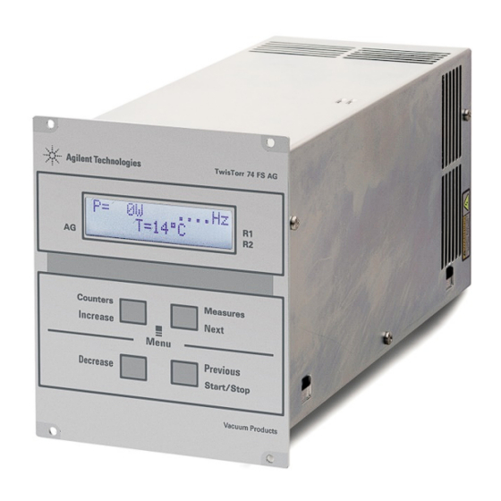
Display alfanumerico a cristalli liquidi: matrice di punti, 2 linee x 16 caratteri. TwisTorr 74FS AG Rack Controller User Manual / 87-901-055-01 21/300... - Page 22 Istruzioni per l’uso Figura 3 Pannello posteriore dei Controller TwisTorr 74 FS AG Connettore di ingresso dei segnali logici (il connettore di accoppiamento viene fornito con l’apposito ponticello di richiusura). Connettore segnali logici in uscita e monitoraggio frequenza pompa più uscita analogica programmabile.
-
Page 23: Procedure Di Uso
AVVERTENZA! Prima di effettuare qualsiasi intervento sul controller scollegare il cavo di alimentazione. Se un controller deve essere eliminato, occorre smaltirlo conformemente agli standard nazionali specifici. TwisTorr 74FS AG Rack Controller User Manual / 87-901-055-01 23/300... -
Page 24: Smaltimento
Istruzioni per l’uso Smaltimento Smaltimento Significato del logo "WEEE" presente sulle etichette. Il simbolo qui sotto riportato è applicato in ottemperanza alla direttiva CE denominata "WEEE". Questo simbolo (valido solo per i paesi della Comunità Europea) indica che il prodotto sul quale è applicato, NON deve essere smaltito insieme ai comuni rifiuti domestici o industriali, ma deve essere avviato ad un sistema di raccolta differenziata. -
Page 25: Messaggi Di Errore
70 °C. temperatura ritorni al di sotto della soglia. Premere Oppure. due volte il pulsante START La temperatura del radiatore del per riavviare la pompa. controller è superiore a 60 °C. TwisTorr 74FS AG Rack Controller User Manual / 87-901-055-01 25/300... - Page 26 Istruzioni per l’uso Messaggi di errore MESSAGGIO DESCRIZIONE AZIONE CORRETTIVA TOO HIGH La corrente ricevuta dalla pompa è Verificare che il rotore della LOAD troppo alta. pompa abbia la possibilità di ruotare liberamente. Premere due volte il pulsante START per riavviare la pompa.
-
Page 27: Gebrauchsanleitung
TwisTorr 74FS AG Rack Controller User Manual Gebrauchsanleitung Allgemeines Lagerung Vor der Installation Installation Gebrauch Steuerungen, Anzeigen und Verbinder des Controllers 32 Fronttafel der Controller Bedienung Einschalten des Controllers Pumpenstart Pumpenstopp Wartung Entsorgung Fehlermeldungen 36 Übersetzung der Originalanleitungen 27/300... -
Page 28: Allgemeines
Gebrauchsanleitung Allgemeines Allgemeines Dieser Apparat ist für Fachbetriebe bestimmt. Vor Gebrauch sollte der Benutzer dieses Handbuch sowie alle weiteren mitgelieferten Zusatzdokumentationen genau lesen. Bei Nichtbeachtung - auch teilweise - der enthaltenen Hinweise, unsachgemäßem Gebrauch durch ungeschultes Personal, nicht autorisierten Eingriffen und Mißachtung der einheimischen, hier zur Geltung kommenden Bestimmungen übernimmt die Firma Agilent keinerlei Haftung. -
Page 29: Lagerung
Beim Transport und bei der Lagerung der Controller müssen folgende klimatische Verhältnisse eingehalten werden: Temperatur: von -20 °C bis +70 °C Relative Luftfeuchtigkeit: 0 – 95 % (nicht kondensierend) TwisTorr 74FS AG Rack Controller User Manual / 87-901-055-01 29/300... -
Page 30: Vor Der Installation
Gebrauchsanleitung Vor der Installation Vor der Installation Der Controller wird mit einer speziellen Schutzverpackung geliefert. Eventuelle Transportschäden müssen der zuständigen örtlichen Verkaufsstelle gemeldet werden. Beim Auspacken vorsichtig vorgehen, damit der Controller nicht fällt oder Stößen ausgesetzt wird. Das Verpackungsmaterial muß korrekt entsorgt werden. Es ist vollständig recyclebar und entspricht der EG-Richtlinie 85/399 für Umweltschutz. -
Page 31: Installation
Gasen ausgesetzt sind und in denen Explosions- und erhöhte Brandgefahr besteht. Beim Betrieb müssen folgende Umgebungsbedingungen eingehalten werden: Temperatur: von +5 °C bis +45 °C Relative Luftfeuchtigkeit: 0 – 95 % (nicht kondensierend). TwisTorr 74FS AG Rack Controller User Manual / 87-901-055-01 31/300... -
Page 32: Gebrauch
Gebrauchsanleitung Gebrauch Gebrauch In diesem Kapitel sind die wichtigsten Betriebsvorgänge aufgeführt. Für weitere Hinweise bezüglich Anschlüsse und Montage des bestellbaren Zubehörs siehe Kapitel "Use" im Anhang zu "Technical Information". Vor Benutzung des Controllers sämtliche elektrischen und pneumatischen Anschlüsse ausführen, und die Betriebsanleitung der angeschlossenen Pumpe durchlesen. -
Page 33: Fronttafel Der Controller
Drücken stoppt die Pumpe. Bei automatischem Pumpenstopp durch Störung muß diese Taste ein erstes Mal zur Controller-Rücksetzung und dann ein zweites Mal zum Neustarten der Pumpe gedrückt werden. Alphanumerisches Flüssigkristall-Display: Punkt-matrix, 2 Zeilen mit 16 Stellen. TwisTorr 74FS AG Rack Controller User Manual / 87-901-055-01 33/300... - Page 34 Gebrauchsanleitung Gebrauch Abbildung 3 Rückseite des Controllers TwisTorr 74 FS AG Eingangsstecker der logischen Signale (passende Buchse wird mit geliefert). Ausganssignalbuchse (logische Signale, Pumpfrequenz, Analogsignale). Stromausgangsstecker (24 V= Pumpkühlventilator, Belüftungsventil und Druckmeßröhre). Netzeingangsmodul des Controllers bestehend aus Netzsicherungen, Netzstecker und EMC Filter.
-
Page 35: Bedienung
Anspruch genommen werden, der für die Erneuerung defekter Controller sorgt. WARNUNG! Vor jedem Eingriff am Controller muß der Netzstecker gezogen werden. Wenn ein Cotroller verschrottet werden muss, muss er entspreched der spezifischen nationalen Vorschriften entsorgt werden. TwisTorr 74FS AG Rack Controller User Manual / 87-901-055-01 35/300... -
Page 36: Entsorgung
Gebrauchsanleitung Entsorgung Entsorgung Bedeutung des "WEEE" Logos auf den Etiketten. Das folgende Symbol ist in Übereinstimmung mit der EU-Richtlinie WEEE (Waste Electrical and Electronic Equipment) angebracht. Dieses Symbol (nur in den EU-Ländern gültig) zeigt an, dass das betreffende Produkt nicht zusammen mit Haushaltsmüll entsorgt werden darf sondern einem speziellen Sammelsystem zugeführt werden muss. -
Page 37: Fehlermeldungen
Warten bis die Temperatur OVERTEMP. 70 °C überschritten. unter den Schwellenwert gesunken ist. Die Pumpe Oder durch zweimalige Die Temperatur des Kontroller- Betätigung der START-Taste kühlkörpers ist über 60 °C. neustarten. TwisTorr 74FS AG Rack Controller User Manual / 87-901-055-01 37/300... - Page 38 Gebrauchsanleitung Fehlermeldungen MELDUNG BESCHREIBUNG BEHEBUNG TOO HIGH Der von der Pumpe abgenommene Sicherstellen, daß der LOAD Strom ist zu stark. Pumpenrotor ungehindert drehen kann. Die Pumpe durch zweimalige Betätigung der START-Taste neustarten. SHORT Es gibt einen Kurzschluss an dem Prüfen Sie die Anschlüsse CIRCUIT Pumpenanschluss.
-
Page 39: Mode D'emploi
TwisTorr 74FS AG Rack Controller User Manual Mode d’emploi Indications générales Emmagasinage Préparation pour l‘installation 42 Installation Utilisation Commandes, Indicateurs et Connecteurs Description du Tableau avant Procédures d'utilisation Allumage du Contrôleur Mise en marche de la Pompe Arrêt de la Pompe... -
Page 40: Indications Générales
Mode d’emploi Indications générales Indications générales Cet appareillage a été conçu en vue d'une utilisation professionnelle. Il est conseillé à l'utilisateur de lire attentivement cette notice d'instructions ainsi que toute autre indication supplémentaire fournie par Agilent, avant l'utilisation de l'appareil. Agilent décline par conséquent toute responsabilité... -
Page 41: Emmagasinage
Pendant le transport et l'emmagasinage des contrôleurs, il faudra veiller à respecter les conditions environnementales suivantes: température: de - 20 °C à + 70 °C humidité relative: de 0% à 95 % (non condensante). TwisTorr 74FS AG Rack Controller User Manual / 87-901-055-01 41/300... -
Page 42: Préparation Pour L'installation
Mode d’emploi Préparation pour l‘installation Préparation pour l‘installation Le contrôleur est fourni dans un emballage de protection spécial; si l'on constate des marques de dommages pouvant s'être produits pendant le transport, contacter aussitôt le bureau de vente local. Pendant l'opération d'ouverture de l'emballage, veiller tout particulièrement à... -
Page 43: Installation
+5 °C à +45 °C humidité relative: de 0 % à 95 % (non condensante). Pour les autres connexions et pour l'installation des accessoires en option, voir la section "Technical Information". TwisTorr 74FS AG Rack Controller User Manual / 87-901-055-01 43/300... -
Page 44: Utilisation
Mode d’emploi Utilisation Utilisation Dans ce paragraphe, on indique les principales procédures opérationnelles. Pour tous autres détails et pour les procédures concernant des connexions ou des éléments en option, se reporter au paragraphe "Use" de l'appendice "Technical Information". Avant d'utiliser le contrôleur, effectuer toutes les connexions électriques et pneumatiques et se référer à... -
Page 45: Commandes, Indicateurs Et Connecteurs
à zéro du contrôleur et une deuxième fois pour remettre la pompe en marche. Ecran alphanumérique à cristaux liquides: matrice de points, 2 lignes x 16 caractères. TwisTorr 74FS AG Rack Controller User Manual / 87-901-055-01 45/300... - Page 46 Mode d’emploi Utilisation Figure 3 Tableau arrière du Contrôleur TwisTorr 74 FS AG Connecteur d'entrée des signaux logiques (le connecteur d'enclenchement est doté de la barrette de réenclenchement spéciale). Connecteur signaux logiques en sortie et monitorage fréquence pompe plus sortie analogique programmables.
-
Page 47: Procédures D'utilisation
à la place du contrôleur défectueux. AVERTISSEMENT! Avant d'effectuer toute opération sur le contrôleur, débrancher le câble d'alimentation. Si le régulateur doit être détruit, il sera éliminé conformément aux normes nationales spécifiques. TwisTorr 74FS AG Rack Controller User Manual / 87-901-055-01 47/300... -
Page 48: Mise Au Rebut
Mode d’emploi Mise au rebut Mise au rebut Signification du logo "WEEE" figurant sur les étiquettes. Le symbole ci-dessous est appliqué conformément à la directive CE nommée "WEEE". Ce symbole (unique-ment valide pour les pays de la Communauté euro-péenne) indique que le produit sur lequel il est appliqué... -
Page 49: Messages D'erreur
70 °C. retourne au-dessous du seuil. Presser deux fois Ou bien l'interrupteur START pour La température du radiateur du remettre la pompe en contrôleur est supérieure à 60 °C. marche. TwisTorr 74FS AG Rack Controller User Manual / 87-901-055-01 49/300... - Page 50 Mode d’emploi Messages d'erreur MESSAGE DESCRIPTION INTERVENTION TOO HIGH Le courant consommé par la pompe S'assurer que le rotor de la LOAD est trop élevé. pompe a la possibilité de tourner librement. Presser deux fois l'interrupteur START pour remettre la pompe en marche.
-
Page 51: Manual De Istrucciones
TwisTorr 74FS AG Rack Controller User Manual Manual de istrucciones Información general Almacenamiento Preparación para la instalación Instalación Mandos, Indicadores y Conectores Descripción del panel frontal 57 Procedimientos de uso Encendido del controler Puesta en marcha de la Bomba 59... -
Page 52: Información General
Manual de istrucciones Información general Información general Este equipo se ha concebido para un uso profesional. El usuario deberá leer atentamente el presente manual de instrucciones y cualquier otra información suplementaria facilitada por Agilent antes de utilizar el equipo. Agilent se considera libre de cualquier responsabilidad debida al incumplimiento total o parcial de las instrucciones, al uso poco apropiado por parte de personal sin formación, a las operaciones no autorizadas o al uso que no cumpla... -
Page 53: Almacenamiento
Durante el transporte y el almacenamiento de los controlers se deberá cumplir con las condiciones ambientales siguientes: temperatura: de -20 °C a +70 °C humedad relativa: 0 – 95 % (no condensadora) TwisTorr 74FS AG Rack Controller User Manual / 87-901-055-01 53/300... -
Page 54: Preparación Para La Instalación
Manual de istrucciones Preparación para la instalación Preparación para la instalación El controler se suministra en un embalaje de protección especial; si se observan señales de daños, que podrían haberse producido durante el transporte, ponerse en contacto con la oficina de venta más cercana. -
Page 55: Instalación
+5 °C a +45 °C humedad relativa: 0 – 95 % (no condensadora). Para otras conexiones y la instalación de los accesorios opcionales, véase la sección “Technical Information”. TwisTorr 74FS AG Rack Controller User Manual / 87-901-055-01 55/300... -
Page 56: Uso
Manual de istrucciones En este apartado se citan los procedimientos operativos principales. Para más detalles y para procedimientos que impliquen conexiones u opcionales especiales, les remitimos al apartado “Use” del anexo “Technical Informations”. Antes de usar el controler efectuar todas las conexiones eléctricas y neumáticas y consultar el manual de la bomba conectada. -
Page 57: Mandos, Indicadores Y Conectores
Display alfanumérico de cristales líquidos: matriz de puntos, 2 líneas x 16 caracteres. TwisTorr 74FS AG Rack Controller User Manual / 87-901-055-01 57/300... - Page 58 Manual de istrucciones Figura 3 Panel trasero del controler TwisTorr 74 FS AG Conector de entrada de las señales lógicas (el conector de acoplamiento se suministra con el conector puente específico de cierre). Conector señales lógicas en salida y monitoreo frecuencia bomba y salida analógica programable.
-
Page 59: Procedimientos De Uso
¡ADVERTENCIA! Antes de efectuar cualquier operación en el controler desenchufar el cable de alimentación. Si tiene que desechar un mando, hágalo siguiendo las normas nacionales específicas. TwisTorr 74FS AG Rack Controller User Manual / 87-901-055-01 59/300... -
Page 60: Eliminación
Manual de istrucciones Eliminación Eliminación Significado del logotipo "WEEE" presente en las etiquetas. El símbolo que se indica a continuación, es aplicado en observancia de la directiva CE denominada "WEEE". Este símbolo (válido sólo para los países miembros de la Comunidad Europea) indica que el producto sobre el cual ha sido aplicado, NO debe ser eliminado junto con los residuos comunes sean éstos domésticos o industriales, y que, por el contrario, deberá... -
Page 61: Mensajes De Error
Apretar dos veces el O bien pulsador START para volver La temperatura del radiador del a poner en marcha la bomba. controler es superior a 60 °C. TwisTorr 74FS AG Rack Controller User Manual / 87-901-055-01 61/300... - Page 62 Manual de istrucciones Mensajes de error MENSAJE DESCRIPCIÓN ACCIÓN CORRECTIVA TOO HIGH La corriente derivada de la bomba Comprobar que el rotor de la LOAD es demasiado alta. bomba tiene la posibilidad de girar libremente. Apretar dos veces el pulsador START para volver a poner en marcha la bomba.
-
Page 63: Manual De Istruções
TwisTorr 74FS AG Rack Controller User Manual Manual de Istruções Informações gerais Armazenagem Preparação para a instalação Instalação Utilização Comandos, Indicadores e Conectores Descrição painel frontal Procedimentos de uso Acendimento do Controller 71 Activação da bomba Paragem da bomba Manutenção Eliminação... -
Page 64: Informações Gerais
Manual de Istruções Informações gerais Informações gerais Esta aparelhagem destina-se ao uso profissional. O utilizador deve ler atentamente o presente manual de instruções e todas as informações adicionais fornecidas pela Agilent antes de utilizar a aparelhagem. A Agilent não se responsabiliza pela inobservância total ou parcial das instruções, pelo uso indevido por parte de pessoas não treinadas, por operações não autorizadas ou pelo uso contrário às normas nacionais específicas. -
Page 65: Armazenagem
Durante o transporte e a armazenagem dos controllers, devem ser satisfeitas as seguintes condições ambientais: temperatura: de -20 °C a + 70 °C humidade relativa: 0 – 95 % (não condensante) TwisTorr 74FS AG Rack Controller User Manual / 87-901-055-01 65/300... -
Page 66: Preparação Para A Instalação
Manual de Istruções Preparação para a instalação Preparação para a instalação O controller é fornecido numa embalagem protectora especial; se apresentar sinais de danos, que poderiam verificar-se durante o transporte, entrar em contacto com o escritório de vendas local. Durante a retirada da embalagem, tomar muito cuidado para não deixar cair o controller e para não submetê-lo a choques. -
Page 67: Instalação
+5 °C a +45 °C humidade relativa: 0 – 95 % (não condensante). Para as outras ligações e a instalação dos acessórios opcionais, ver a secção "Technical Information". TwisTorr 74FS AG Rack Controller User Manual / 87-901-055-01 67/300... -
Page 68: Utilização
Manual de Istruções Utilização Utilização Neste parágrafo são descritos os principais procedimentos operativos. Para maiores detalhes e para procedimentos que envolvem ligações ou peças opcionais, consultar o parágrafo "Use" do apêndice "Technical Information". Antes de usar o controller, efectuar todas as ligações eléctricas e pneumáticas e consultar o manual da bomba ligada. -
Page 69: Comandos, Indicadores E Conectores
Display alfanumérico com cristais líquidos: matriz de pontos 2 linhas x 16 caracteres. TwisTorr 74FS AG Rack Controller User Manual / 87-901-055-01 69/300... - Page 70 Manual de Istruções Utilização Figura 3 Painel posterior dos Controllers TwisTorr 74 FS AG Conector de entrada dos sinais lógicos (o conector de acoplamento é fornecido com ponte específica de fecho). Conector sinais lógicos na saída e monitoragem freqüência bomba mais saída analógica programável.
-
Page 71: Procedimentos De Uso
ATENÇAO! Antes de efectuar qualquer operação no controller, desligar o cabo de alimentação. Se um controlador precisar de ser eliminado, deve ser descartado em conformidade com as normas nacionais específicas. TwisTorr 74FS AG Rack Controller User Manual / 87-901-055-01 71/300... -
Page 72: Eliminação
Manual de Istruções Eliminação Eliminação Significado do logótipo "WEEE" presente nos rótulos. O símbolo abaixo indicado é aplicado de acordo com a directiva CE denominada "WEEE". Este símbolo (válido apenas para os países da Comunidade Europeia) indica que o produto no qual está aplicado NÃO deve ser eliminado juntamente com os resíduos domésticos ou industriais comuns, mas deve ser dirigido a um sistema de recolha diferenciada. -
Page 73: Mensagens De Erro
70 ºC. estabelecido. Premer duas vezes o botão START para reactivar a bomba. A temperatura do radiador do controller é superior a 60 °C. TwisTorr 74FS AG Rack Controller User Manual / 87-901-055-01 73/300... - Page 74 Manual de Istruções Mensagens de erro MENSAGEM DESCRIÇÃO ACÇÃO CORRECTIVA TOO HIGH A corrente gerada pela bomba é Verificar se o rotor da LOAD demasiado alta. bomba pode rodar livremente. Premer duas vezes o botão START para reactivar a bomba. SHORT Um curto-circuito está...
-
Page 75: Bedrijfshandleiding
TwisTorr 74FS AG Rack Controller User Manual Bedrijfshandleiding Algemene informatie 76 Opslag Voorbereiding voor installatie Installatie Gebruik Bedieningsorganen, Controlelampjes en Connectoren van Beschrijving frontpaneel Gebruiksprocedures Inschakelen van de controller Starten van de pomp Stoppen van de pomp 83 Onderhoud Afvalverwerking 84... -
Page 76: Algemene Informatie
Bedrijfshandleiding Algemene informatie Algemene informatie Deze apparatuur is bestemd voor beroepsmatig gebruik. De gebruiker wordt verzocht aandachtig deze handleiding en alle overige door Agilent verstrekte informatie door te lezen alvorens het apparaat in gebruik te nemen. Agilent acht zich niet aansprakelijk voor de gevolgen van het niet of gedeeltelijk in acht nemen van de aanwijzingen, onoordeelkundig gebruik door niet hiervoor opgeleid personeel, reparaties waarvoor geen toestemming is verkregen of... -
Page 77: Opslag
Tijdens het transport en de opslag van de controllers moeten de volgende omgevingscondities aanwezig zijn: temperatuur: van -20 °C tot +70 °C relatieve vochtigheid: 0 – 95 % (niet condenserend) TwisTorr 74FS AG Rack Controller User Manual / 87-901-055-01 77/300... -
Page 78: Voorbereiding Voor Installatie
Bedrijfshandleiding Voorbereiding voor installatie Voorbereiding voor installatie De controller wordt in een speciale beschermende verpakking geleverd; als er schade wordt geconstateerd die tijdens het transport veroorzaakt zou kunnen zijn, meteen contact opnemen met het plaatselijke verkoopkantoor. Zorg er bij het uitpakken voor dat de controller niet kan vallen of stoten te verduren krijgt. -
Page 79: Installatie
+5 °C tot +45 °C relatieve vochtigheid: 0 – 95 % (niet condenserend). Voor de overige aansluitingen en de installatie van de accessoires wordt verwezen naar het hoofdstuk "Technical Information". TwisTorr 74FS AG Rack Controller User Manual / 87-901-055-01 79/300... -
Page 80: Gebruik
Bedrijfshandleiding Gebruik Gebruik In deze paragraaf worden de voornaamste bedieningswijzen uitgelegd. Voor meer informatie of procedures die aansluitingen of speciale opties betreffen wordt verwezen naar de paragraaf "Use" van de bijlage "Technical Informations". Breng, alvorens de controller in gebruik te nemen, alle elektrische en pneumatische aansluitingen tot stand en raadpleeg hiervoor de handleiding van de aan te sluiten pomp. -
Page 81: Bedieningsorganen, Controlelampjes En Connectoren Van
Alfanumeriek display met vloeibare kristallen (LCD): puntjespatroon, 2 lijnen x 16 karakters. TwisTorr 74FS AG Rack Controller User Manual / 87-901-055-01 81/300... - Page 82 Bedrijfshandleiding Gebruik Figuur 3 Achterpaneel van de controllers TwisTorr 74 FS AG Connector voor ingang logische signalen (de te koppelen connector wordt met de speciale sluitklem geleverd). Connector voor uitgang logische signalen en frequentiecontrole pomp plus programmeerbare analogische uitgang. Uitgangsaansluiting voeding (24 Vdc voor de koelventilator van de pomp, vent valve en manometer).
-
Page 83: Gebruiksprocedures
WAARSCHUWING! Alvorens werkzaamheden aan de controller uit te voeren, de voedingskabel afkoppelen. Mocht de controller gesloopt worden, ga dan overeenkomstig de specifieke nationale wetgeving te werk. TwisTorr 74FS AG Rack Controller User Manual / 87-901-055-01 83/300... -
Page 84: Afvalverwerking
Bedrijfshandleiding Afvalverwerking Afvalverwerking Betekenis van het logo "WEEE" op de etiketten. Het onderstaande symbool wordt aangebracht in overeenstemming met de EG-richtlijn "WEEE". Dit symbool (alleen geldig voor de landen van de Europese Gemeenschap) geeft aan dat het product waarop het is aangebracht, NIET mag worden afgevoerd samen met mormaal huisvuil of industrieel afval, maar gescheiden moet worden ingezameld. -
Page 85: Foutmeldingen
Bedien twee maal de START- De temperatuur van de radiator van knop om de pomp weer op te de controller bedraagt meer dan starten. 60 °C. TwisTorr 74FS AG Rack Controller User Manual / 87-901-055-01 85/300... - Page 86 Bedrijfshandleiding Foutmeldingen BOODSCHAP OMSCHRIJVING REMEDIE TOO HIGH De huidige trek door de pomp is te Controleer of de pomprotor vrij LOAD hoog. kan draaien. Bedien twee maal de START- knop om de pomp weer op te starten. SHORT Er is kortsluiting op de Inspecteer de aansluitingen en CIRCUIT pompconnector.
-
Page 87: Istruktionsbog
TwisTorr 74FS AG Rack Controller User Manual Istruktionsbog Generel Information Opbevaring Forberedelser før installation Installation Anvendelse Indikatorer og Kontakter på Styreenheden Beskrivelse af frontpanel Instruktion Start af styreenheden 95 Start af pumpen Stop af pumpen Vedligeholdelse 95 Bortskaffelse Fejlmeddelelser Oversættelse af originalinstruktionerne... -
Page 88: Generel Information
Istruktionsbog Generel Information Generel Information Dette materiel er beregnet til professionel anvendelse. Brugeren bør læse denne brugsanvisning og anden yderligere information fra Agilent, før udstyret anvendes. Agilent tager ikke ansvar for skader helt eller delvis som følge af tilsidesættelse af disse instruktioner, fejlagtig brug af personer uden tilstrækkelig kendskab, ukorrekt anvendelse af udstyret eller håndtering, der strider imod gældende lokale regler. -
Page 89: Opbevaring
BEMÆRK Opbevaring Følgende krav til omgivelsesforholdene gælder ved transport og opbevaring af styreenheden: temperatur: fra -20 °C til +70 °C relativ luftfugtighed: 0 – 95 % (ikke kondenserende) TwisTorr 74FS AG Rack Controller User Manual / 87-901-055-01 89/300... -
Page 90: Forberedelser Før Installation
Istruktionsbog Forberedelser før installation Forberedelser før installation Styreenheden leveres i en speciel beskyttende emballage. Kontakt den lokale forhandler, hvis emballagen viser tegn på skader, der kan være opstået under transporten. Sørg for at styreenheden ikke tabes eller udsættes for stød ved udpakningen. Smid ikke emballagen ud. -
Page 91: Installation
Følgende krav til omgivelsesforholdene gælder ved drift: temperatur: fra +5 °C til +45 °C relativ luftfugtighed: 0 – 95 % (ikke kondenserende) For øvrige tilslutninger og installation af tilbehør henvises til afsnittet "Technical Information". TwisTorr 74FS AG Rack Controller User Manual / 87-901-055-01 91/300... -
Page 92: Anvendelse
Istruktionsbog Anvendelse Anvendelse Dette afsnit beskriver de vigtigste driftsprocedurer. For en detaljeret beskrivelse samt procedurer, der involverer tilslutninger eller tilbehør, henvises til afsnittet "Use" i bilag "Technical Information". Inden styreenheden anvendes, bør samtlige elektriske og pneumatiske tilslutninger udføres. Læs brugsanvisningen før pumpen tilsluttes. -
Page 93: Indikatorer Og Kontakter På Styreenheden
Hvis pumpen standser automatisk ved en fejl, tryk på denne knap en gang for at tilbagestille styreenheden, og yderligere en gang for at starte pumpen igen. LCD-display med tal og bogstaver: punktmatrice, 2 rader med 16 tegn. TwisTorr 74FS AG Rack Controller User Manual / 87-901-055-01 93/300... - Page 94 Istruktionsbog Anvendelse Figur 3 Bagpanelet på Styreenheden TwisTorr 74 FS AG Indgangskontakt til logiske signaler (tilslutningskontakten leveres med speciel forbindelsesbro). Udgangskontakt til logiske signaler og kontrol af pumpens frekvens samt programmerbar analog udgang. Udtag (24 Vdc til blæseren der køler pumpen, udluftningsventilen og trykmåleren). Indgangsmodul til styreenhed omfattende sikringer, strømudtag og ENC filter.
-
Page 95: Instruktion
ADVARSEL! Inden der foretages noget som helst indgreb på styreenheden, skal strømmen først afbrydes. Hvis en regulator skal kasseres, skal den bortskaffes i henhold til de specifikke nationale standarder. TwisTorr 74FS AG Rack Controller User Manual / 87-901-055-01 95/300... -
Page 96: Bortskaffelse
Istruktionsbog Bortskaffelse Bortskaffelse Betydningen af "WEEE" logoet på mærkaterne. Nedenstående symbol anvendes i overensstemmelse med det såkaldte EU-direktiv "WEEE". Symbolet (kun gældende for EU-landene) viser, at produktet, som det sidder på IKKE må bortskaffes sammen med affald fra private husholdninger eller industriel affald men skal indleveres på... -
Page 97: Fejlmeddelelser
Vent på at temperaturen OVERTEMP. overskrider 70 °C. falder til under tærskelværdi. Tryk to gange på START for eller at starte pumpen igen. Temperaturen på styreenhedens køler overskrider 60 °C. TwisTorr 74FS AG Rack Controller User Manual / 87-901-055-01 97/300... - Page 98 Istruktionsbog Fejlmeddelelser MEDDELELSE BESKRIVELSE KONTROL TOO HIGH Den strøm, der trækkes af pumpen Kontrollér om pumpens rotor LOAD er for høj. kan rotere frit. Tryk to gange på START for at starte pumpen igen. SHORT En kortslutning er til stede på Kontrollér tilslutningerne og CIRCUIT pumpetilslutningen.
-
Page 99: Bruksanvisning
TwisTorr 74FS AG Rack Controller User Manual Bruksanvisning Allmän Information Förvaring Förberedelser för installation Installation Användning Indikatorer och Kontakterpå Styrenheten Beskrivning av frontpanel Instruktioner för bruk Start av styrenheten Start av pumpen Stopp av pumpen 107 Underhåll Bortskaffning Felmeddelanden 109 Översättning av originalinstruktionerna... -
Page 100: Allmän Information
Bruksanvisning Allmän Information Allmän Information Utrustningen är avsedd för yrkesmässig användning. Användaren bör läsa denna bruksanvisning, samt övrig dokumentation från Agilent före användning av utrustningen. Agilent tar inget ansvar för skador som helt eller delvis orsakats av åsidosättande av instruktionerna, olämplig användning av person utan tillräcklig kunskap, obehörigt bruk av utrustningen eller hantering som strider mot gällande lokala föreskrifter. -
Page 101: Förvaring
OBSERVERA Förvaring Följande krav på omgivningsförhållanden gäller vid transport och förvaring av styrenheten: temperatur: från -20 °C till +70 °C relativ luftfuktighet: 0 – 95 % (utan kondens) TwisTorr 74FS AG Rack Controller User Manual / 87-901-055-01 101/300... -
Page 102: Förberedelser För Installation
Bruksanvisning Förberedelser för installation Förberedelser för installation Styrenheten levereras i ett särskilt skyddande emballage. Kontakta det lokala försäljningskontoret om emballaget visar tecken på skador som kan ha uppstått under transporten. Se till att styrenheten inte tappas eller utsätts för stötar vid uppackningen. -
Page 103: Installation
Följande krav på omgivningsförhållanden gäller vid drift: temperatur: från +5 °C till +45 °C relativ luftfuktighet: 0 – 95 % (utan kondens) Beträffande övriga anslutningar och installation av tillbehör hänvisas till avsnittet "Technical Information". TwisTorr 74FS AG Rack Controller User Manual / 87-901-055-01 103/300... -
Page 104: Användning
Bruksanvisning Användning Användning Detta avsnitt beskriver de viktigaste driftmomenten. För en detaljerad beskrivning samt beträffande moment som involverar anslutningar eller tillbehör hänvisas till avsnittet "Use" i bilaga "Technical Information". Innan styrenheten används bör samtliga elektriska och pneumatiska anslutningar utföras. Läs bruksanvisningen för den anslutna pumpen. -
Page 105: Indikatorer Och Kontakterpå Styrenheten
återställa styrenheten, och ytterligare en gång för att starta om pumpen. LCD-display med siffror och bokstäver: punktmatris, 2 rader med 16 tecken. TwisTorr 74FS AG Rack Controller User Manual / 87-901-055-01 105/300... - Page 106 Bruksanvisning Användning Figur 3 Bakre panel på Styrenheten TwisTorr 74 FS AG Ingångskontakt för logiska signaler (anslutnings-kontakten levereras med speciell stängningsbrygga). Kontakt för utgående logiksignaler och kontroll av pumpfrekvens plus programmerbar analog utgång. Uttag (24 Vdc för kylfläkt, avluftningsventil och manometer). Inmodul för styrenhet omfattande säkringar, strömuttag och ENC filter.
-
Page 107: Instruktioner För Bruk
VARNING! Innan något arbete utförs på styrenheten måste dess strömförsörjning brytas. Om en styrenhet måste skrotas så ska den kastas bort i enlighet med de särskilda nationella standarderna. TwisTorr 74FS AG Rack Controller User Manual / 87-901-055-01 107/300... -
Page 108: Bortskaffning
Bruksanvisning Bortskaffning Bortskaffning Betydelse av logotypen "WEEE" på etiketterna. Symbolen som visas nedan har tillämpats i enlighet med CD-direktivet som har betecknats som "WEEE". Den här symbolen (gäller endast i de länder som tillhör den Europeiska Unionen) indikerar att produkten på vilken symbolen har applicerats INTE får skaffas bort tillsammans med vanliga hushålls- eller industriavfall, men att däremot ett differentierat uppsamlingssystem måste upprättas. -
Page 109: Felmeddelanden
Vänta tills temperaturen OVERTEMP. överskrider 70 °C. sjunker under tröskelvärdet. Tryck två gånger på knappen eller också START för att starta om Temperaturen på styrenhetens pumpen. kylare överskrider 60 °C. TwisTorr 74FS AG Rack Controller User Manual / 87-901-055-01 109/300... - Page 110 Bruksanvisning Felmeddelanden MEDDELANDE BESKRIVNING ÅTGÄRD TOO HIGH Den ström som förbrukas av Kontrollera att pumpens rotor LOAD pumpen är för hög. kan rotera fritt. Tryck två gånger på knappen START för att starta om pumpen. SHORT En kortslutning finns på Kontrollera kopplingar och CIRCUIT pumpkopplingen.
-
Page 111: Instruksjon Manual
TwisTorr 74FS AG Rack Controller User Manual Instruksjon Manual Generell informasjon 112 Lagring Forberede installasjonen Installasjon Bruk 116 Indikatorer og Kontakter på Styreenheten Beskrivelse av frontpanelet Instruksjoner for bruk 119 Starte styreenheten Starte pumpen Stoppe pumpen Vedlikehold Eliminering Feilmeldinger Oversetting av den opprinnelige samsvarserklæringen... -
Page 112: Generell Informasjon
Instruksjon Manual Generell informasjon Generell informasjon Dette utstyret er beregnet til bruk av profesjonelle brukere. Brukeren bør lese denne brukerveiledningen og all annen informasjon fra Agilent før utstyret tas i bruk. Agilent kan ikke holdes ansvarlig for hendelser som skjer på grunn av manglende oppfølging, selv delvis, av disse instruksjonene, feilaktig bruk av utrenet personell, ikke godkjente endringer av utstyret eller handlinger som på... -
Page 113: Lagring
Merknadene inneholder viktig informasjon som er hentet fra teksten. MERK Lagring Når styreenhetene transporteres eller lagres, må følgende forhold være oppfylt: temperatur: fra 20 °C til +70 °C relativ fuktighet: 0 – 95 % (uten kondens) TwisTorr 74FS AG Rack Controller User Manual / 87-901-055-01 113/300... -
Page 114: Forberede Installasjonen
Instruksjon Manual Forberede installasjonen Forberede installasjonen Styreenheten leveres i en spesiell beskyttelsesemballasje. Viser denne tegn på skader som kan ha oppstått under transporten, må du ta kontakt med det lokale salgskontoret. Når styreenheten pakkes ut, må du passe på at den ikke slippes ned eller utsettes for noen form for støt. -
Page 115: Installasjon
+5 °C til +45 °C relativ fuktighet: 0 – 95 % (uten kondens) Når det gjelder andre tilkoplinger og installasjon av ekstrautstyr vises det til avsnittet "Technical Information". TwisTorr 74FS AG Rack Controller User Manual / 87-901-055-01 115/300... -
Page 116: Bruk
Instruksjon Manual Bruk Bruk Dette avsnittet beskriver de viktigste driftsmomentene. For en detaljert beskrivelse samt moment som omfatter tilkoplinger eller ekstrautstyr vises det til avsnittet "Use" i vedlegget "Technical Information”. Før styreenheten tas i bruk bør samtlige elektriske og pneumatiske tilkoplinger gjøres. Les brukerveiledningen for pumpen som er tilkoplet. -
Page 117: Indikatorer Og Kontakter På Styreenheten
å stanse pumpen. Har pumpen stanset automatisk i forbindelse med en feil, trykk en gang på denne knappen for å tilbakestille styreenheten, en gang til for å startet pumpen. LCD-display med siffer og bokstaver: punkt-matrise, 2 rader med 16 tegn. TwisTorr 74FS AG Rack Controller User Manual / 87-901-055-01 117/300... - Page 118 Instruksjon Manual Bruk Figur 3 Bakpanelet på styreenheten TwisTorr 74 FS AG Inngangskontakt for logiske signaler (tilkoplings-kontakten leveres med spesiell lukkebrygge). Port for logiske signaler ut og monitoring av pumpefrekvens og analogisk utgang programmerbar. Uttak (24 Vdc på kjøleviften, på pumpen, vifte ventil og manometer). Inngangsmodul til mating av styreenheten som består av sikringer, matekontakt og ENC- filter.
-
Page 119: Instruksjoner For Bruk
ødelagte styreenheten. ADVARSEL! Før noe arbeid utføres på styreenheten, må den frakoples strømnettet. Dersom en kontroller må skrotes, så må den bli kastet i henhold med spesifikke nasjonale standarder. TwisTorr 74FS AG Rack Controller User Manual / 87-901-055-01 119/300... -
Page 120: Eliminering
Instruksjon Manual Eliminering Eliminering Betydelsen av symbolet på logo "WEEE" på etikettene. Symbolet nedenunder som finnes, er anvendt i henhold til EC-direktiv kalt "WEEE". Dette symbolet (som bare gjelder for land i Det europeiske fellesselskap), viser at produktet som det sitter på, IKKE må behandles som vanlig hus-industriavfall, men må... -
Page 121: Feilmeldinger
Vent til temperaturen synker OVERTEMP. over 70 °C. under terskelverdien. Trykk to ganger på knappen Eller START for å starte pumpen. Temperaturen på radiatoren på styreenheten er over 60 °C. TwisTorr 74FS AG Rack Controller User Manual / 87-901-055-01 121/300... - Page 122 Instruksjon Manual Feilmeldinger MELDING BESKRIVELSE FORHOLDSREGEL TOO HIGH Strømmen dratt av pumpen er for Kontroller om pumpens rotor LOAD høyt. kan rotere fritt. Trykk to ganger på knappen START for å starte pumpen. SHORT En kortslutning er tilstede på Sjekk tilkoblinger og CIRCUIT pumpekoblingen.
-
Page 123: Ohjekäsikirja
TwisTorr 74FS AG Rack Controller User Manual Ohjekäsikirja Yleisiä tietoja Varastointi Valmistelut asennusta varten Asennus Käyttö Valvojan Säätimet, Osoittimet ja Liittimet Etupaneelin kuvaus Käyttötoimenpiteet Valvojan käynnistys Pumpun käynnistys Pumpun pysäyttäminen Huolto Hävittäminen Vianetsintä Alkuperäisen ohjeiden käännös 123/300... -
Page 124: Yleisiä Tietoja
Ohjekäsikirja Yleisiä tietoja Yleisiä tietoja Tämä laite on tarkoitettu ammattimaiseen käyttöön. Ennen laitteen käyttöönottoa käyttäjän tulee lukea huolellisesti mukana seuraava käyttöohje sekä kaikki muut Agilentin toimittamat lisätiedot. Agilent ei vastaa seurauksista, jotka johtuvat laitteen käyttöohjeiden täydellisestä tai osittaisesta laiminlyömisestä, ammattitaidottomien henkilöiden suorittamasta laitteen virheellisestä... -
Page 125: Varastointi
HUOM Varastointi Valvojan kuljetuksen ja varastoinnin aikana tulevat seuraavat ympäristövaatimukset olla täytettyinä: lämpötila: -20 °C ja +70 °C asteen välillä suhteellinen kosteus: 0 – 95 % (ilman lauhdetta) TwisTorr 74FS AG Rack Controller User Manual / 87-901-055-01 125/300... -
Page 126: Valmistelut Asennusta Varten
Ohjekäsikirja Valmistelut asennusta varten Valmistelut asennusta varten Valvoja toimitetaan erityisessä suojaavassa pakkauksessa. Mikäli havaitsette mahdollisesti kuljetuksen aikana tapahtuneita vaurioita, ottakaa yhteys paikalliseen myyntitoimistoon. Pakkauksen purkamisen yhteydessä huolehtikaa, että valvoja ei pääse putoamaan ja välttäkää sen joutumista iskujen kohteeksi. Älkää jättäkö pakkausta ympäristöön. Materiaali voidaan kokonaisuudessaan kierrättää... -
Page 127: Asennus
5 °C ja +45 °C välillä suhteellinen kosteus: 0 - 95% välillä (ilman lauhdetta) Muiden kytkentöjen ja valinnaisten lisälaitteiden asennusten suorittamiseksi, katsokaa kappaletta "Technical Information". TwisTorr 74FS AG Rack Controller User Manual / 87-901-055-01 127/300... -
Page 128: Käyttö
Ohjekäsikirja Käyttö Käyttö Tähän kappaleeseen on kirjattu tärkeimmät käyttötoimenpiteet. Tarkempia lisätietoja sekä kytkentöjä ja valinnaisia lisälaitteita koskevien toimenpiteiden suorittamista käsitteleviä tietoja löydätte kappaleesta "Käyttö", joka on "Tekniset tiedot"- kappaleen liitteenä. Ennen valvojan käyttöä suorittakaa kaikki sähkökytkennät seuraten kytkettävän pumpun käyttöohjeita. VAROITUS! Tutustu pumpun käyttöohjeeseen ennen aloittamista pumpun turvalliseksi käyttämiseksi. -
Page 129: Valvojan Säätimet, Osoittimet Ja Liittimet
Mikäli pumppu on toimintahäiriön vuoksi pysähtynyt automaattisesti, painakaa painonappia yhden kerran, jolloin valvoja saadaan asetettua uudelleen .Toisen kerran painonappia painettaessa pumppu käynnistyy. Kirjainnumerollinen digitaalinäyttö: pistematriisi, 2 riviä x 16 merkkiä. TwisTorr 74FS AG Rack Controller User Manual / 87-901-055-01 129/300... - Page 130 Ohjekäsikirja Käyttö Kuva 3 Valvojien TwisTorr 74 FS AG takapaneli Logiikkasegnaalien tulokytkentä (pariliittimet toimitetaan niihin sopivilla yhdyskaapelisulkijalla). Lähtevien logiikkasignaalien ja pumpun taajuuden tarkkailun sekä ohjelmoitavan analogisen ulostulon liitin. Virran ulostuloliitin (24 V tasavirta pumpun jäähdytystuulettimelle, ilmanpoistoventtiilille ja tyhjiömittarille). Valvojan tulovirran moduuli, johon sisältyvät sulakkeet, virtapistoke ja suodatin ENC. Profibus-osoitteen asettamiseen tarkoitettu kiertokytkin (valinnainen).
-
Page 131: Käyttötoimenpiteet
VAROITUS! Ennen minkä tahansa valvojaan tehtävän toimenpiteen suorittamista irrottakaa sähkökaapeli pistorasiasta. Jos ohjain joudutaan postamaan käytöstä, tulee se hävittää noudattaen erityisiä kansallisia standardeja. TwisTorr 74FS AG Rack Controller User Manual / 87-901-055-01 131/300... -
Page 132: Hävittäminen
Ohjekäsikirja Hävittäminen Hävittäminen Pakkausmerkinnöissä olevan WEEE-logon merkitys. Alla näkyvä merkki on lisätty pakkaukseen EY:n ns. WEEE-direktiivin mukaisesti. Merkki (koskee ainoastaan Euroopan Unionin jäsenmaita) tarkoittaa, että tuotetta EI saa hävittää tavallisen kotitalous- tai teollisuusjätteen mukana, vaan se on toimitettava erilliseen keräyspisteeseen. Loppukäyttäjää kehotetaan sen vuoksi ottamaan keräys- ja hävittämisprosessia varten yhteyttä... -
Page 133: Vianetsintä
CONTROLLER Valvojan muuntajan lämpötila on Odottakaa, että lämpötila OVERTEMP. 70 °C. putoaa kynnysarvon alapuolelle. Painakaa painonappia START kaksi kertaa jolloin pumppu Valvojan lämmittimen lämpötila käynnistyy. on korkeampi kuin 60 °C. TwisTorr 74FS AG Rack Controller User Manual / 87-901-055-01 133/300... - Page 134 Ohjekäsikirja Vianetsintä VIESTI VIKA KORJAUSTOIMENPITEET TOO HIGH Pumpun nykyinen virtaama on Tarkistakaa, että pumpun LOAD liian korkea. roottori pyörii vapaasti. Painakaa painonappia START kaksi kertaa jolloin pumppu käynnistyy. SHORT Pumpun liitin on oikosulussa. Tarkista liitännät ja oikosulut CIRCUIT pumpun ja ohjaimen välillä. Painakaa painonappia START kaksi kertaa jolloin pumppu käynnistyy.
-
Page 135: Felhasználói Kézikönyv
TwisTorr 74FS AG Rack Controller User Manual Felhasználói Kézikönyv Általános információk Tárolás A telepítésre való előkészítés Telepítés Használat A vezérlő parancsai, kijelzői és csatlakozói Az előlap leírása 141 Használati eljárások A vezérlő bekapcsolása A szivattyú beindítása 143 A szivattyú leállítása Karbantartás... -
Page 136: Általános Információk
Felhasználói Kézikönyv Általános információk Általános információk Ez a berendezés hivatásos használatra tervezett. A felhasználónak, a berendezés használatát megelőzően, gondosan el kell olvasnia e felhasználói kézikönyvet és minden egyéb, a Agilent által szolgáltatott információt. A Agilent elhárít magától minden esetleges felelősséget, mely a felhasználói utasítások teljes vagy részleges figyelmen kívül hagyásához, a nem kiképzett személyzet által történő... -
Page 137: Tárolás
Tárolás A vezérlők szállítása és tárolása során az alábbi környezeti feltételeket kell biztosítani: hőmérséklet: -20 °C és +70 °C között relatív nedvességtartalom: 0 – 95 % (nem lecsapódó). TwisTorr 74FS AG Rack Controller User Manual / 87-901-055-01 137/300... -
Page 138: A Telepítésre Való Előkészítés
Felhasználói Kézikönyv A telepítésre való előkészítés A telepítésre való előkészítés A vezérlő speciális védőcsomagolásban kerül leszállításra; ha ez károsodás jeleit mutatja, melyek a szállítás során keletkezhettek, kapcsolatba kell lépni a helyi forgalmazó irodával. A kicsomagolás során különleges figyelmet kell fordítani arra, hogy a vezérlő... -
Page 139: Telepítés
+5 °C és +45 °C között; relatív nedvességtartalom: 0 – 95 % (nem lecsapódó). A többi összekötéssel és az opcionális kiegészítő felszerelések telepítésével kapcsolatosan lásd a ”Technical Information” című alfejezetet. TwisTorr 74FS AG Rack Controller User Manual / 87-901-055-01 139/300... -
Page 140: Használat
Felhasználói Kézikönyv Használat Használat Ebben a szakaszban a fontosabb működési eljárások kerülnek ismertetésre. További részletek és az összekötéseket vagy az opcionális elemeket érintő eljárások találhatók a “Technical Information” melléklet “Use” című szakaszában. A vezérlő használata előtt valamennyi elektromos és pneumatikus összeköttetést létre kell hozni, és figyelembe kell venni a csatlakoztatott szivattyú... -
Page 141: A Vezérlő Parancsai, Kijelzői És Csatlakozói
(reset), a másodikra a szivattyú újraindul. Folyadékkristályos alfanumerikus kijelző: pontmátrixos, 2 sor x 16 karakter. TwisTorr 74FS AG Rack Controller User Manual / 87-901-055-01 141/300... - Page 142 Felhasználói Kézikönyv Használat Ábra 3 A TwisTorr 74 FS AG számú vezérlők hátlapja Logikai jelek bemeneti csatlakozója (az összekötő csatlakozó megfelelő lezáró átkötéssel (jumper) van ellátva). Csatlakozó a kimeneti logikai jelek, a szivattyúfrekvencia ellenőrzése és programozható analóg kimenet számára. Kimeneti tápcsatlakozó (24 Vdc szivattyú hűtőventillátor, légtelenítő szelep és idomszer). Bementei tápellátó...
-
Page 143: Használati Eljárások
VESZÉLY! A vezérlőn való bármely beavatkozás végrehajtása előtt ki kell húzni a hálózati csatlakozót. A vezérlőegység leselejtezésének szükségessége esetén, a megsemmisítés az erre vonatkozó nemzeti szabványok betartásával kell történjen. TwisTorr 74FS AG Rack Controller User Manual / 87-901-055-01 143/300... -
Page 144: Megsemmisítés
Felhasználói Kézikönyv Megsemmisítés Megsemmisítés A címkén jelenlévő "WEEE" logo jelentése. Az alább látható szimbólum az EK "WEEE" elnevezésű irányelvével összhangban kerül alkalmazásra. Ez a szimbólum (mely csak az Európai Közösség országaiban érvényes), azt jelzi, hogy a termék, melyen megtalálható, NEM kerülhet közönséges háztartási vagy ipari hulladékkal együtt megsemmisítésre, hanem azt egy szelektív hulladékgyűjtő... -
Page 145: Hibaüzenetek
Várakozni, míg a hőmérséklet OVERTEMP. túllépte a 70 °C-t, a küszöbérték alá esik. A szivattyú újraindításához vagy kétszer megnyomni a START a vezérlő hűtésének hőmérséklete nyomógombot. túllépte a 60 °C-t. TwisTorr 74FS AG Rack Controller User Manual / 87-901-055-01 145/300... - Page 146 Felhasználói Kézikönyv Hibaüzenetek ÜZENET LEÍRÁS JAVÍTÁSI TEVÉKENYSÉG TOO HIGH A szivattyú áramfelvétele túl nagy. Ellenőrizni, hogy a szivattyú LOAD forgórésze szabadon foroghat- e. A szivattyú újraindításához kétszer megnyomni a START nyomógombot. SHORT A szívattyú csatlakozója zárlatos. Ellenőrízze az összeköttetést CIRCUIT és rövidzárlatokat a szivattyú...
-
Page 147: Podrecznik Instrukcji
TwisTorr 74FS AG Rack Controller User Manual Podrecznik Instrukcji Informacje ogolne Magazynowanie 149 Przygotowanie do instalacji Instalacja Uzytkowanie Sterowniki, Wskazniki I Laczniki Opis pulpitu frontalnego Procedure uzytkowania Zaswiecenie kontrolera Uruchomienie pompy Zatrzymanie pompy Konserwacja Przetworstwo odpadow Bledne informacje 156 Az eredeti utasítás fordítása... -
Page 148: Informacje Ogolne
Podrecznik Instrukcji Informacje ogolne Informacje ogolne Urzadzenie to jest przeznaczone do uzytku zawodowego. Przed przystapieniem do korzystania uzytkownik powinien wnikliwie przesledzic zarowno ten podrecznik zawierajacy instrukcje jak rowniez kazda inna dostarczona przez Agilent informacje.Agilent uchyla sie od jakiejkolwiek odpowiedzialnosci w przypadku calkowitego lub czesciowego nie przestrzegania swoich instrukcji, przeznaczenia urzadzenia niezgodnie z jego przeznaczeniem i jego obslugi przez personel uprzednio nie przeszkolony, naprawy urzadzenia bez... -
Page 149: Magazynowanie
Przypisy zawieraja najwazniejsze informacje wyciagniete z tekstu. PRZYPIS Magazynowanie Kontrolery podczas transportu i przechowywania w magazynie powinny miec nastepujace warunki otoczenia: temperatura: od -20 °C do +70 °C wilgotnosc wzgledna: od 0-95 %(nie kondensujaca). TwisTorr 74FS AG Rack Controller User Manual / 87-901-055-01 149/300... -
Page 150: Przygotowanie Do Instalacji
Podrecznik Instrukcji Przygotowanie do instalacji Przygotowanie do instalacji Kontroler zostaje dostarczony w specjalnym, ochronnym opakowaniu; jezeli opakowanie prezentuje jakiekolwiek uszkodzenia ktore moglyby powstac podczas transportu wowczas nalezy niezwlocznie powiadomic najblizszy, lokalny punkt sprzedazy. Podczas operacji rozpakowywania nalezy zachowac specjalna ostroznosc zeby nie spowodowac upadku kontrolera lub nie narazic na uderzenia. -
Page 151: Instalacja
Podczas pracy kontrolera nalezy zapewnic nastepujace warunki otoczenia: temperatura: od +5 °C do +45 °C wilgotnosc wzgledna: 0 – 95 % (nie kondensujaca). Sposob polaczenia i instalowania akcesoriow jest opisany w rozdziale “Technical Information”. TwisTorr 74FS AG Rack Controller User Manual / 87-901-055-01 151/300... -
Page 152: Uzytkowanie
Podrecznik Instrukcji Uzytkowanie Uzytkowanie Paragraf ten zawiera podstawowe procedury operatywne. Dla uzyskania dodatkowych bardziej szczegolowych informacji lub dostepu do procedur na temat polaczen lub akcesoriow skonsultowac paragraf “Use“ znajdujacy sie w dodatku do “Technical Information“. Przed przystapieniem do uzytkowania kontrolera wykonac wszystkie polaczenia elektryczne i pneumatyczne podlaczenie pompy konsultowac z odnosna instrukcja. -
Page 153: Sterowniki, Wskazniki I Laczniki
I poraz drugi zeby uruchomic pompe. Display alfanumeryczny na cieklych krysztalach: matryca punktowana, 2 linie x 16 czcionek. TwisTorr 74FS AG Rack Controller User Manual / 87-901-055-01 153/300... - Page 154 Podrecznik Instrukcji Uzytkowanie ć 3 Posta Pulpit tylny kontrolerow TwisTorr 74 FS AG Lacznik wejsciowy sygnalow logicznych (lacznik blizniaczy jest dostarczany z specialnym mostkiem zamykajacym. Lacznik wyjsciowy sygnalow logicznych i nadzor nad czestotlowoscia na wyjsciu podczas zaprogramowanej, wielokrotnej pracy pompy. Lacznik zasilania na wyjsciu (24 Vdc dla turbiny chlodzacej pompy, zawor odpowietrzajacy i wskaznik).
-
Page 155: Procedure Uzytkowania
ZAGROZENIE! Przed wykonaniem jakiejkolwiek interwencji na kontrolerze nalezy odlaczyc kabel zasilajacy. W przypadku konieczności złomowania urządzenia sterującego, należy się go pozbyć zgodnie z normami krajowymi. TwisTorr 74FS AG Rack Controller User Manual / 87-901-055-01 155/300... -
Page 156: Przetworstwo Odpadow
Podrecznik Instrukcji Przetworstwo odpadow Przetworstwo odpadow Objasnienie znajdujacego sie na etykiecie znaczenia logo “WEEE”. Uzyty ponizej symbol jest zgodny z wymogiem zarzadzenia “WEEE” Unii Europejskiej. Symbol ten (prawomocny tylko w krajach Unii Europejskiej) oznacza, ze wyrob ktory nim zostal oznaczony NIE moze byc przetworzony jako odpad razem z innymi domowymi lub przemyslowymi natomiast musi byc skladowany w miejscu przeznaczonym dla odpadow do przerobki zroznicowanej . -
Page 157: Bledne Informacje
Temperatura w kontrolerze Odczekac az temperatura sie OVERTEMP. przekroczyla 70 °C. obnizy ponizej ustalonego poziomu. Nacisnac dwa razy przycisk Temperatura grzejnika nie START dla ponownego przekracza 60 °C. uruchomienia pompy. TwisTorr 74FS AG Rack Controller User Manual / 87-901-055-01 157/300... - Page 158 Podrecznik Instrukcji Bledne informacje INFORMACJA OPIS AKCJA KORYGUJACA TOO HIGH Prąd pobierany przez pompę jest Sprawdzic czy wirnik nie ma LOAD zbyt wysoki. przeszkod w swobodnym obrocie. Nacisnac dwa razy przycisk START dla ponownego uruchomienia pompy. SHORT Na złączu pompy występuje Należy sprawdzić...
-
Page 159: Návod K Použití
TwisTorr 74FS AG Rack Controller User Manual Návod k Použití Všeobecné informace Uskladnění Příprava k instalaci Instalace Použití Ovládání, indikátory a konektory Popis čelního panelu Používané procedury 167 Zapalování Kontroléru 167 Spouštění čerpadla Zastavení čerpadla Údržba Likvidace Chybné zprávy Překlad originálního návodu... -
Page 160: Všeobecné Informace
Návod k Použití Všeobecné informace Všeobecné informace Tento přístroj je určen pro profesionální potřebu. Uživatel si musí před použitím tuto příručku velmi pozorně přečíst, ale i každou další aktualizaci, kterou podnik bude předávat. V důsledku nedostatečného i částečně nesprávného použití, nebo v případě chyb nevyškoleného personálu či neoprávněných zásahů... -
Page 161: Uskladnění
Uskladnění Během dopravy a skladování kontrolérů, se musí dbát na následující podmínky prostředí: temperatura: od -20 °C do +70 °C relativní vlhkost: 0 – 95 % (nesmí kondenzovat). TwisTorr 74FS AG Rack Controller User Manual / 87-901-055-01 161/300... -
Page 162: Příprava K Instalaci
Návod k Použití Příprava k instalaci Příprava k instalaci Kontrolér je dodáván v speciálním ochranném balení; objeví-li se následkem dopravy nějaké poškození, je třeba se okamžitě obrátit na místní prodejní servis. Během rozbalování se obzvlášť musí dávat pozor, aby kontrolér nespadl nebo aby neutrpěl nárazy. Balicí materiál se nesmí... -
Page 163: Instalace
5 °C do +45 °C Relativní vlhkost: 0 – 95 % (nesmí kondenzovat). Pro další spojení a instalaci opčního příslušenství je třeba se podívat do sekce "Technical Information". TwisTorr 74FS AG Rack Controller User Manual / 87-901-055-01 163/300... -
Page 164: Použití
Návod k Použití Použití Použití V tomto odstavci jsou uvedeny hlavní operativní postupy. Pro další detajly i pro procedury týkající se spojení nebo dalších opčních detajlů, je třeba se obracet na odstavec "Use" v příloze "Technical Information". Veškerá elektrická a pneumatická spojení se musí vykonat před použitím kontroléru, při čemž... -
Page 165: Ovládání, Indikátory A Konektory
Jestliže se čerpadlo automaticky zastaví z důvodu nějaké poruchy, tlačítko se musí napoprvé stisknout, aby se uskutečnil reset kontroléru a po druhé aby se čerpadlo znovu spustilo. Alfanumerický displej na tekuté krystaly: matice bodů, 2 linky x 16 charakterů. TwisTorr 74FS AG Rack Controller User Manual / 87-901-055-01 165/300... - Page 166 Návod k Použití Použití Postava 3 Zadní panel Kontroléru TwisTorr 74 FS AG Vstupní konektor logických signálů (konektor spojky je dodáván s příslušným znovu zavírajícím můstkem). Konektor výstupních logických signálů a monitorování frekvence čerpadla plus naprogramovatelný analogový výstup. Konektor výstupu napájení (24 Vdc na ochlazovací lopatku čerpadla, odvzdušňovací ventil a vakuoměr).
-
Page 167: Používané Procedury
"Agilent advanced exchange service", kde poškozený kontrolér bude vyměněn za nový. NEBEZPEČÍ! Nejdříve, před jakýmkoliv zásahem na kontroléru, se musí odpojit elektrický kabel. Pokud má být vyřazen ovladač, musí být vyřazen v souladu se specifickými národními normami. TwisTorr 74FS AG Rack Controller User Manual / 87-901-055-01 167/300... -
Page 168: Likvidace
Návod k Použití Likvidace Likvidace Význam loga "WEEE" nacházejícího se na štítku. Níže uvedený symbol odpovídá směrnicím CE pojmenovaným "WEEE". Tento symbol (platný jen pro státy Evropské Unie) určuje, že výrobek, který je takto označen NESMÍ být likvidován společně s ostatními domácími nebo průmyslovými odpady, ale je nutno ho předat do patřičných provozních sběren, kde musí... -
Page 169: Chybné Zprávy
Temperatura kontroléru převýšila Vyčkat až se temperatura opět OVERTEMP. 70 °C. vrátí pod mezní hodnotu. Stisknout dvakrát tlačítko Nebo START pro opětné spuštění Teplota radiátoru kontroléru je vyšší čerpadla. než 60 °C. TwisTorr 74FS AG Rack Controller User Manual / 87-901-055-01 169/300... - Page 170 Návod k Použití Chybné zprávy ZPRÁVY POPIS KOREKCE TOO HIGH Proud čerpaný pumpou je příliš Prověřit, zda rotor čerpadla se LOAD vysoký. může volně otáčet. Stisknout dvakrát tlačítko START pro opětné spuštění čerpadla. SHORT Na konektoru pumpy je zkrat. Zkontrolujte zapojení a zkraty CIRCUIT mezi pumpou a ovladačem.
-
Page 171: Návod Na Obsluhu
TwisTorr 74FS AG Rack Controller User Manual Návod na Obsluhu Všeobecné informácie Uskladňovanie Príprava pre inštaláciu Inštalácia Použitie Povely, Ukazovatele a Prípojky “Controller” Popis čelného panelu 177 Postup pri použití Zapnutie “Controller” Naštartovanie čerpadla Zastavenie čerpadla Údržba Likvidácia Oznamy vád Preklad originálneho návodu... -
Page 172: Všeobecné Informácie
Návod na Obsluhu Všeobecné informácie Všeobecné informácie Tento prístroj slúži k profesionálnemu použitiu. Užívateľ si pred použitím tohto prístroja musí pozorne prečítať tento návod k použitiu a jeho ďalšie doplnky, dodané podnikom Agilent. Podnik Agilent nepreberá na seba žiadnu zodpovednosť za úplné, alebo čiastočné nedodržiavanie návodu, za nesprávne používanie prístroja nekompetentnými osobami, za nepovolené... -
Page 173: Uskladňovanie
POZNÁMKA Uskladňovanie Počas prepravy a uskladňovania “Controllers” musia byť dodržané tieto podmienky prostredia: teplota: od -20 °C do +70 °C relatívna vlhkosť: 0 – 95 % (bez kondenzátu). TwisTorr 74FS AG Rack Controller User Manual / 87-901-055-01 173/300... -
Page 174: Príprava Pre Inštaláciu
Návod na Obsluhu Príprava pre inštaláciu Príprava pre inštaláciu “Controller” je dodaný v špeciálnom ochrannom obale; keby ste objavili škodu, spôsobenú prepravou, skontaktujte sa s kanceláriou miestneho predaja. Pri rozbaľovaní dávajte pozor, aby vám “Controller” nespadol, alebo niekde nenarazil. Obal nezahadzujte. Je vyrobený z recyklovateľného materiálu a zodpovedá... -
Page 175: Inštalácia
Počas chodu je dôležité, aby boli rešpektované tieto podmienky prostredia: teplota: od +5 °C do +45 °C; relatívna vlhkosť: 0 – 95 % (nekondenzovaná). Pre ostatné napojenia a inštaláciu zvoliteľného príslušenstva viď časť "Technical Information". TwisTorr 74FS AG Rack Controller User Manual / 87-901-055-01 175/300... -
Page 176: Použitie
Návod na Obsluhu Použitie Použitie V tomto odstavci sú uvedené hlavné operatívne postupy. Pre ostatné detaily a pre postupy, ktoré sa vzťahujú na napojenia, alebo na zvolené príslušenstvo, postupujte podľa časti "Use" v dodatku "Technical Information". Pred použitím “Controller” preveďte všetky potrebné elektrické a pneumatické... -
Page 177: Povely, Ukazovatele A Prípojky "Controller
Keď sa čerpadlo v prípade poruchy zastaví automaticky, treba stlačiť tlačidlo prvý krát pre resetovanie “controller” a druhý krát pre znovunaštarovanie čerpadla. Alfanumerický displej na tekutý kryštál: bodová matica, 2 línie x 16 písmen. TwisTorr 74FS AG Rack Controller User Manual / 87-901-055-01 177/300... - Page 178 Návod na Obsluhu Použitie Postava 3 Zadný panel “controller TwisTorr 74 FS AG Vstupná spojka logických signálov (spojovacia spojka je doganá s príslušným uzavierajúcim mostíkom). Spojka východzích logických signálov a monitorovanie frekvencie čerpadla a navyše programovateľný analogický výstup. Výstupá spojka napájania (24 Vdc pre chladiacu lopatku čerpadla, odvzdušňovací ventil a vákuometer).
-
Page 179: Postup Pri Použití
“controller”. NEBEZPEČÍE! Pred akýmkoľvek zásahom na “controller” vytiahnite šnúru z elektrickej siete. Ak je potrebné odstrániť kontrolór, likvidácia musí prebehnúť v súlade so špecifickými štátnymi normami. TwisTorr 74FS AG Rack Controller User Manual / 87-901-055-01 179/300... -
Page 180: Likvidácia
Návod na Obsluhu Likvidácia Likvidácia Význam loga "WEEE" nachádzajúceho sa na štítkoch. Aplikovanie doluozznačeného symbolu dodržuje smernicu EÚ s názvom "WEEE". Tento symbol (platný iba pre štáty Európskej Únie) znamená, že výrobok s týmto štítkom NESMIE byť odstránený spolu s bežným domácim alebo priemyselným odpadom, ale sa musí... -
Page 181: Oznamy Vád
START pre znovunaštartovanie čerpadla. CONTROLLER Teplota “controller” prekročila 70 Počkať, kým teplota neklesne OVERTEMP. °C. pod hranicu. Stlačte dvakrát tlačidlo START pre Alebo znovunaštartovanie čerpadla Teplota radiátora controllera presahuje 60 °C. TwisTorr 74FS AG Rack Controller User Manual / 87-901-055-01 181/300... - Page 182 Návod na Obsluhu Oznamy vád OZNAM POPIS ZÁSAH OPRAVY TOO HIGH Nastavený ťah čerpadla je príliš Skontrolujte, či má rotor LOAD vysoký. čerpadla možnosť točiť sa voľne. Stlačte dvakrát tlačidlo START pre znovunaštartovanie čerpadla SHORT Na konektore čerpadla je krátky Skontrolujte zapojenie a krátke CIRCUIT obvod.
-
Page 183: Priročnik Za Navodila
TwisTorr 74FS AG Rack Controller User Manual Priročnik za Navodila Splošne informacije Skladiščenje Priprava za montažo Montaža Uporaba Komande, indikatorji in konektorji Opis prednje plošče Postopki uporabe Vklopitev Controllera Zagon črpalke Zaustavitev črpalke Vzdrževanje Odlaganje opadkov Obvestilo o napaki Prevod navodil v izvirniku... -
Page 184: Splošne Informacije
Priročnik za Navodila Splošne informacije Splošne informacije Naprava je namenjena samo za strokovno rabo. Uporabnik mora temeljito prebrati priročnik in pri tem upoštevati vsako dodatno informacijo, ki jo nudi Agilent. Agilent ne odgovarja v slučaju celotnega ali delnega nespoštovanja navodil, pri nepravilni uporabi nestrokovnega osebja, v slučaju nedovoljenih posegov ali pri zanemarjenju specifičnih nacionalnih meril. -
Page 185: Skladiščenje
Opombe vsebujejo vse najbolj pomembne informacije iz besedila. OPOMBA Skladiščenje Med prevozom in skladiščenjem controllerjev morate zagotoviti naslednje pogoje okolice: temperatura: od -20 °C do +70 °C relativna vlaga: 0 – 95 % (bez kondenzacije). TwisTorr 74FS AG Rack Controller User Manual / 87-901-055-01 185/300... -
Page 186: Priprava Za Montažo
Priročnik za Navodila Priprava za montažo Priprava za montažo Controller dobite v posebni zaščitni embalaži; če so na embalaži znaki poškodbe, ki naj bi nastale med transportom obrnite se krejavnemu prodajalnemu biroju. Pri odstranitvi embalaže morate še posebno paziti, da controller ne pade na tla ali da ne podlegne udarcem. -
Page 187: Montaža
+5 °C do +45 °C; relativna vlaga: 0 – 95 % (ne-kondezna). Kar se tiče priključkov in montaže opcionalnih dodatkov, si lahko ogledate priponko "Technical Information". TwisTorr 74FS AG Rack Controller User Manual / 87-901-055-01 187/300... -
Page 188: Uporaba
Priročnik za Navodila Uporaba Uporaba V tem odsatvku so navedeni vsi glavni operativni postopki. Za dodatne detalje in postopke, ki zadevajo priključitve ali posamezne opcije, si lahko ogledate odstavek "Use" v priponki "Technical Information". Predno bi uporabili controller, morate priključiti vse električne in pnevmatske kable, pri tem se nanajšate na priročnik priložene črpalke. -
Page 189: Komande, Indikatorji In Konektorji
črpalko zaustavili. Če se je črpalka sama zaustavila zaradi kvara, morate to tipko enkrat pritisniti, da bi lahko controller-a resetirali in še drugič za ponoven zagon črpalke. Alfaštevilčni zaslon iz tekočih kristalov: prebijalo bodov, 2 linije x 16 znaka. TwisTorr 74FS AG Rack Controller User Manual / 87-901-055-01 189/300... - Page 190 Priročnik za Navodila Uporaba Slika 3 Ozadnja plošča Controllera TwisTorr 74 FS AG Vhodni konektor logičnih signalov (spajalni konektor ima ustrezen zapiralni mostiček) Konekotr logičnih izhodnih signalov in nadzor frekvence črpalke plus analogični izhod, ki lahko programirate. Izhodni napajalni konektor (24 V za hladilni ventilator črpalke, odzračevalni ventil in merilnik).
-
Page 191: Postopki Uporabe
Vam bo dal na razpolago obnovljeni controller. SVARILO! Pred katerikoli posegom, izklopite iz controller-a. napajalni kabel Če je treba krmilnik zavreči, ga je treba zavreči v skladu s specifičnimi nacionalnimi standardi. TwisTorr 74FS AG Rack Controller User Manual / 87-901-055-01 191/300... -
Page 192: Odlaganje Opadkov
Priročnik za Navodila Odlaganje opadkov Odlaganje opadkov Pomen znamke "WEEE" na etiketah. Spodaj navedeni simbol je v skladu z direktivo ES znano pod imenom "WEEE". Ta simbol (ki velja samo v državah Evropske Skupnosti) pomeni, da izdelek NE SMETE ODSTRANITI skupaj z ostalimi komunalnimi ali pa industrijskimi odpadki, temveč... -
Page 193: Obvestilo O Napaki
Temperatura controllera je presegla Počakajte, da se temperatura OVERTEMP. 70 °C. vrne pod normalnim vrednostnim pragom. Dvakrat pritisnite tipko START za Temperatura controllerskega ponoven zagon črpalke. radiatorja je višja od 60 °C. TwisTorr 74FS AG Rack Controller User Manual / 87-901-055-01 193/300... - Page 194 Priročnik za Navodila Obvestilo o napaki OBVESTILO OPIS POPRAVA TOO HIGH Jakost toka, ki ga porabi črpalka, je Preverite, da lahko rotor LOAD previsoka. črpalke prosto vrti. Dvakrat pritisnite tipko START za ponoven zagon črpalke. SHORT Na konektorju črpalke je prisoten Preverite priključke in kratke CIRCUIT kratek stik.
-
Page 195: Instructions For Use
TwisTorr 74FS AG Rack Controller User Manual Instructions for Use General Information Storage Preparation for Installation Installation Controls, Indicators and Connectors Front Panel Description 201 Use Procedure Controller Startup Starting the Pump Pump Shutdown Maintenance Disposal Error Messages Original Instructions... -
Page 196: General Information
Instructions for Use General Information General Information This equipment is destined for use by professionals. The user should read this instruction manual and any other additional information supplied by Agilent before operating the equipment. Agilent will not be held responsible for any events occurring due to non-compliance, even partial, with these instructions, improper use by untrained persons, non-authorised interference with the equipment or any action contrary to that provided for by specific national standards. -
Page 197: Storage
When transporting and storing the controllers, the following environmental requirements should be satisfied: temperature: from -20 °C to + 70 °C relative humidity: 0 – 95 % (without condensation) TwisTorr 74FS AG Rack Controller User Manual / 87-901-055-01 197/300... -
Page 198: Preparation For Installation
Instructions for Use Preparation for Installation Preparation for Installation The controller is supplied in a special protective packing. If this shows signs of damage which may have occurred during transport, contact your local sales office. When unpacking the controller ensure that it is not dropped or subjected to any form of impact. -
Page 199: Installation
0 – 95 % (without condensation). See the appendix “Technical Information” for detailed Information about the above mentioned and the other connections, and about the options installation. TwisTorr 74FS AG Rack Controller User Manual / 87-901-055-01 199/300... -
Page 200: Use
Instructions for Use This paragraph describes the fundamental operating procedures. Detailed information and operating procedures that envolve optional connection or option are supplied in the paragraph “USE” of the appendix “Technical Information”. Make all vacuum manifold and electrical connections and refer to TwisTorr pump instruction manual before operating the TwisTorr controller. -
Page 201: Controls, Indicators And Connectors
If the pump has been stopped automatically by a fault, this push-button must be pressed once to reset the controller and a second time to restart the pump. LCD back-lighted alphanumeric display: dot matrix 2 lines x 16 characters. TwisTorr 74FS AG Rack Controller User Manual / 87-901-055-01 201/300... - Page 202 Instructions for Use Figure 3 Controller TwisTorr 74 FS AG Rear panel Logic input signals connectors (mating connector supplied with link). Logic output signals connector and pump frequency monitor plus programmable analog output. Power output connector (24 Vdc for pump cooling fan, Vent Valve and Gauge). Controller power entry module consisting of mains fuses, mains socket and EMC filter.
-
Page 203: Use Procedure
Before carrying out any work on the controller, disconnect it from the supply. If a controller needs to be scrapped, it must be disposed off in accordance with the specific national standards. TwisTorr 74FS AG Rack Controller User Manual / 87-901-055-01 203/300... -
Page 204: Disposal
Instructions for Use Disposal Disposal Meaning of the "WEEE" logo found in labels The following symbol is applied in accordance with the EC WEEE (Waste Electrical and Electronic Equipment) Directive. This symbol (valid only in countries of the European Community) indicates that the product it applies to must NOT be disposed of together with ordinary domestic or industrial waste but must be sent to a differentiated waste collection system. -
Page 205: Error Messages
The controller environment Wait until the temperature OVERTEMP. temperature exceeds 70°C. decreases below threshold value. Press the START push-button The controller radiator temperature twice to start the pump. is above 60°C. TwisTorr 74FS AG Rack Controller User Manual / 87-901-055-01 205/300... - Page 206 Instructions for Use Error Messages MESSAGE DESCRIPTION REPAIR ACTION TOO HIGH The current drawn by the pump is Check that the pump rotor is LOAD too high. free to rotate. Press the START push-button twice to start the pump. SHORT A short circuit is present on the Check connections and short CIRCUIT...
-
Page 207: Technical Information
TwisTorr 74FS AG Rack Controller User Manual Technical Information TwisTorr 74 FS AG Rack Controller Description 209 Controller Specifications Controller Outline Controller Connection J6 – Fan 213 J7 – Vent 214 P1 – Input 215 J1 – Output R1 – R2 Output Diagrams 220... - Page 208 Technical Information Error Messages Programming Configuration Menu Mode Menu Pump Setting Menu Input/Output Menu Setpoint R1 and Setpoint R2 Submenus Gauge Menu Serial Menu How to Use by Remote I/0 How to Use in Serial Mode Profibus Option 275 General Installation Configuration 276 Software Operation and State Machine...
-
Page 209: Twistorr 74 Fs Ag Rack Controller Description
Provides and acquires the pressure of the wide range gauge. Remote I/Os compatible with the previous version. Speed reading after stop command. See the following diagram for the connections and orderable parts. TwisTorr 74FS AG Rack Controller User Manual / 87-901-055-01 209/300... - Page 210 Technical Information TwisTorr 74 FS AG Rack Controller Description PUMP AIR COOLING KIT VENT VALVE VENT VALVE EXTENSION CABLE AIR COOLING KIT EXTENTION CABLE CONTROLLER J2-SERIAL J4-PROFIBUS LS D PUMP MS D TO POWER MAINS FUS E T YPE T 4A SUPPLY VENT GAUGE...
-
Page 211: Controller Specifications
LpA < 70 dB(A), normal operation, operator position The controller supplied voltage must be easily disconnected (through a circuit NOTE bracker or having access to the power supply cable plug). TwisTorr 74FS AG Rack Controller User Manual / 87-901-055-01 211/300... -
Page 212: Controller Outline
Technical Information Controller Outline Controller Outline The outline dimensions for the TwisTorr 74 FS AG Rack Controllers are shown in the following figure. The TwisTorr controller can be used as a bench unit or as a rack module, in any NOTE case it must be positioned so that free air can flow through the housing holes. -
Page 213: Controller Connection
This connection has to be used with TwisTorr 74 FS pump cooling fan (see orderable parts table). Adapter cables are available to connect other fans. Figure 6 Fan Connector TwisTorr 74FS AG Rack Controller User Manual / 87-901-055-01 213/300... - Page 214 Technical Information Controller Connection J7 – Vent Figure 7 Vent Connector This is the connection to control the optional vent valve (see orderable parts table). The vent valve can be driven by controller automatically or by serial line. If you have other vent valves installed (110 Vac powered), it must be replaced (see orderable parts table).
- Page 215 If active before the start command Imax = 5mA operation, and activates the soft start procedure. To Imin (on) = 2mA in STOP be used only at first pump run-up. status. TwisTorr 74FS AG Rack Controller User Manual / 87-901-055-01 215/300...
- Page 216 Technical Information Controller Connection The following figure shows a typical contact logic input connection and the related simplified circuit of the controller. Figure 10 Typical logic input connection J1 – Output Figure 11 Logic output connector All the logic output from the controller must be connected at J1 mating connector.
- Page 217 Technical Information Controller Connection Figure 12 Digital Output Connection Example Figure 13 Analog Output Connection Example TwisTorr 74FS AG Rack Controller User Manual / 87-901-055-01 217/300...
- Page 218 Technical Information Controller Connection Tab. 4 Pins Name Description Electrical Note 15-8 Fault 0V = no fail Optically isolated See note 1. Vmax (=open) = 24V 24V = fail Connect a 10kohm Vlow, max = 1,5V resistor between the Imax = 60mA 2 pins before Pin-8 negative measuring voltage...
- Page 219 When the analog output is set to provide pressure signal, the voltage level is proportional to pressure level and it is generated by control unit elaborating the independent input by the active gauge. TwisTorr 74FS AG Rack Controller User Manual / 87-901-055-01 219/300...
- Page 220 Technical Information Controller Connection A load should be present to measure the voltage on open collector output; if not NOTE 1 present connect 10 kohm resistor between the related pins. The R1 and R2 output behaviours can be configured thorugh the serial NOTE 2 communication as described in the serial communication window meaning table.
-
Page 221: R1 - R2 Output Diagrams
R1 – R2 Output Diagrams R1 – R2 Output Diagrams Figure 14 Diagram 1 – R1 or R2 related to frequency Figure 15 Diagram 2 – R1 or R2 related to power TwisTorr 74FS AG Rack Controller User Manual / 87-901-055-01 221/300... - Page 222 Technical Information R1 – R2 Output Diagrams Figure 16 Diagram 3 – R1 or R2 related to time V (Volt) R1-R2 Stop Waiting Ramp Auto Braking Normal Fail t (sec) Interlock tuning Figure 17 Diagram 4 – R1 or R2 related to Normal status Figure 18 Diagram 5 –...
-
Page 223: Programmable Analog Output Diagrams
Figure 20 Diagram 2 – Programmable analog output related to power V (Volt) Output Voltage Pump Temp (°C) Figure 21 Diagram 3 – Programmable analog output related to pump temperature TwisTorr 74FS AG Rack Controller User Manual / 87-901-055-01 223/300... - Page 224 Technical Information Programmable Analog Output Diagrams Pump Connector The controller is equipped with a 5 meter long cable. The following figure shows the controller output connector configuration where pins: A-F = pump temperature sensor B-C-D = 76 V AC 3-phase output to pump motor stator ...
- Page 225 (these ÷ g_min g_max values can be drawn from the gauge technical specifications). GAUGE IDENTIFICATION SIGNAL COMMON +25VDC P MAX 2W COMMON SIGNAL Figure 23 Gauge Connector TwisTorr 74FS AG Rack Controller User Manual / 87-901-055-01 225/300...
- Page 226 Technical Information Programmable Analog Output Diagrams With the serial communication you can use the following windows: Win 163 Pressure measurement unit (0=mbar, 1= Pascal, 2=Torr) Win 224 Pressure reading with the format X.X E Win 257 Gauge status (read only): 0 ...
- Page 227 (Win 107 = Active Stop, Win 167 = Stop Speed Reading). Active Stop brakes the pump using the motor. The Stop Speed reading reads the actual pump speed after a stop command. Figure 24 Diagram 5 TwisTorr 74FS AG Rack Controller User Manual / 87-901-055-01 227/300...
-
Page 228: J2 - Serial Connector
Technical Information J2 – Serial Connector J2 – Serial Connector This connector provides the connection for RS-232 and RS-485 serial line. J2 Pin-out: Figure 25 J2 Connector Tab. 6 PIN N. SIGNAL NAME +5 V (OUT) (Reserved) TX (RS-232) RX (RS-232) A+ (RS-485) B- (RS-485) RESERVED... - Page 229 Technical Information J2 – Serial Connector Connector Examples TwisTorr 74 FS AG Rack Controller Figure 26 RS-232 Connection Figure 27 RS-485 Connection TwisTorr 74FS AG Rack Controller User Manual / 87-901-055-01 229/300...
- Page 230 Technical Information J2 – Serial Connector The communication port mating connector is supplied with the RS-232 PCB (AMP/Cannon or equivalent 15-pin "D" type male connector). For example, the Transmit data signal from controller (pin 2) must be connected to the host computer's receive data line (pin 2) and vice versa.
-
Page 231: Letter Protocol Description
"B" = STOP "C" = Low Speed ON "D" = Low Speed OFF "E" = Request for operational parameters "F" = Pump times zeroing TwisTorr 74FS AG Rack Controller User Manual / 87-901-055-01 231/300... - Page 232 Technical Information Letter Protocol Description "G" = Parameters reading "H" = Parameters writing "I" = Request for operating status "J" = Request for numerical reading "K" = Request for counters reading. CRC corresponds to the sum (with inverted sign) of all the preceding bytes.
- Page 233 2 = STARTING 3 = NORMAL OPERATION 4, 5 = HIGH LOAD 6 = FAILURE 7 = APPROACHING LOW SPEED 2÷5 Cycle Time 6÷9 Pump Life 10÷11 Pump Temperature Current* TwisTorr 74FS AG Rack Controller User Manual / 87-901-055-01 233/300...
- Page 234 Technical Information Letter Protocol Description BYTES MEANING Voltage* 14÷17 Frequency 18÷19 Cycle # R1 Status R2 Status *The values for current and voltage are given as numbers, scaled from 0 to 255, where 0 corresponds to 0 V and 255 to the full scale voltage (130 V) or current (2,5 A).
- Page 235 3 = NORMAL OPERATION 4, 5 = HIGH LOAD 6 = FAILURE 7 = APPROACHING LOW SPEED R2 status 0 = OFF 1 = ON R1 status 0 = OFF 1 = ON TwisTorr 74FS AG Rack Controller User Manual / 87-901-055-01 235/300...
- Page 236 Technical Information Letter Protocol Description When the Request is "J" (Numerical readings), the Answer will contain a string of 5 characters with the following parameters: Tab. 12 BYTES MEANING Current (0-255 scaled) Voltage (0-255 scaled) Rotational speed KRPM Pump temperature °C (0-254 temperature reading, 255 = fail) When the Request is "K"...
- Page 237 When a data is indicated between two quotes (‘...’) it means that the indicated NOTE data is the corresponding ASCII character. When a number is indicated with Ox prefix it means it is an hexadecimal number (16 base coded). TwisTorr 74FS AG Rack Controller User Manual / 87-901-055-01 237/300...
- Page 238 Technical Information Letter Protocol Description <STX> (Start of transmission) = 0x02 <ADDR> (Unit address) = 0x80 (for RS 232) <ADDR> (Unit address) = 0x80 + device number (0 to 31) (for RS 485) <WIN> (Window) = a string of 3 numeric character indicating the window number (from ‘000’...
- Page 239 Win Disabled 1 byte (0x35) the specified window is Read Only or temporarily disabled (for example you can’t write the Soft Start when the Pump is running) TwisTorr 74FS AG Rack Controller User Manual / 87-901-055-01 239/300...
-
Page 240: Examples
Technical Information Examples Examples Command: START Source: PC Destination: Controller ADDR WINDOW Source: Controller Destination: PC ADDR Command: STOP Source: PC Destination: Controller ADDR WINDOW Source: Controller Destination: PC ADDR 240/300 TwisTorr 74 FS AG Rack Controller User Manual / 87-901-055-01... - Page 241 Technical Information Examples Command: SOFT-START (ON) Source: PC Destination: Controller ADDR WINDOW Source: Controller Destination: PC ADDR Command: SOFT-START (OFF) Source: PC Destination: Controller ADDR WINDOW Source: Controller Destination: PC ADDR TwisTorr 74FS AG Rack Controller User Manual / 87-901-055-01 241/300...
- Page 242 Technical Information Examples Command: READ PUMP STATUS Source: PC Destination: Controller (with address = 3) ADDR WINDOW Source: Controller (with address = 3 in stop status) Destination: PC ADDR WINDOW DATA (STATUS) Command: READ SERIAL TYPE Source: PC Destination: Controller (with address = 3 in 485 mode) ADDR WINDOW Source: Controller...
- Page 243 Baud rate 600 = 0 1200 = 1 2400 = 2 4800 = 3 9600 = 4 (default = 4) Pump life/ cycle time/ cycle number To reset write ‘1’ TwisTorr 74FS AG Rack Controller User Manual / 87-901-055-01 243/300...
- Page 244 Technical Information Examples reset Interlock type (default = 0) Impulse = 0 Continuous = 1 0 = frequency Analog output type: output voltage signal 1 = power proportional to frequency, power, (default = 1) temperature or pressure 2 = Pump temperature 3 = Pressure Rotational frequency setting (Hz) Low speed...
- Page 245 = + or - 0 = Starting (Output ON Start Output Mode only with pump Status = Starting) 1 = running (Output ON when the pump is running) (default -0) TwisTorr 74FS AG Rack Controller User Manual / 87-901-055-01 245/300...
- Page 246 Technical Information Examples Gas type 0 = not configured 1 = Nitrogen 2 = Argon 3 = Idrogen 4 =other Gas correction Pump current in mA dc Pump voltage in Vdc Pump power in W (pump current x pump voltage duty cycle) Driving frequency in Hz Pump temperature in °C 0 to 70...
- Page 247 2. On command means that the vent valve is opened or closed by means of window n. 122. TOO HIGH LOAD NO CONNECTION SHORT CIRCUIT PUMP OVERTEMP. OVERVOLTAGE CONTROLL. OVERTEMP. AUX FAIL POWER FAIL Figure 28 Window N. 206 Bit Description TwisTorr 74FS AG Rack Controller User Manual / 87-901-055-01 247/300...
-
Page 248: How To Use By Front Panel
Technical Information How to Use by Front Panel How to Use by Front Panel Figure 29 Start Stop and Reset Fail button Press once for the START command and again for the STOP command. In the case of controller’s failure, press once to reset the fail condition. - Page 249 Pressing a third time, the following message is displayed: Model Number of the controller Serial Number By pressing the key again, the display returns back to the main screen. Measures Pressing once, the following is displayed: ° TwisTorr 74FS AG Rack Controller User Manual / 87-901-055-01 249/300...
- Page 250 Technical Information How to Use by Front Panel Where: P = XXX W is the current power supplied to the pump T = XX °C is the current temperature of the pump XXXX Hz is the driving frequency of the pump. This value is set by default to 1167 Hz but can be modified by the user according to needs, proceeding as described in the “PROGRAMMING”...
- Page 251 PRESSURE OVER: indicates that the pressure measured is above the maximum measurement threshold set. The unit of measurement of the pressure can be selected (GAUGE menu→Unit) from “mBar”,”Pa”,”torr” Pressing 4 times returns to the following screen page: TwisTorr 74FS AG Rack Controller User Manual / 87-901-055-01 251/300...
- Page 252 Technical Information How to Use by Front Panel Where: NORMAL: indicates the operating regime of the pump XXXHz: is the driving frequency of the pump (for further details please see the description “Pressing once” the Measures key) The operating mode of the controller is shown at the bottom in the center.
-
Page 253: Use
The input signal J1 interlock should be left in position including the shipping NOTE links if no external connections are made. The forepump and the TwisTorr pump can be switched on at the same time. TwisTorr 74FS AG Rack Controller User Manual / 87-901-055-01 253/300... - Page 254 Technical Information Startup Plug the controller power cable into a suitable power source. The display lights up for approx. 2 seconds and shows: After 2 seconds, the display shows the following screen page: If the pump is not connected, the display will be as follows: NOTE ...
- Page 255 X; the user may decide to express this value in Hz (default) or in KRMP. Once operating speed has been reached, the following screen page is displayed: TwisTorr 74FS AG Rack Controller User Manual / 87-901-055-01 255/300...
- Page 256 Technical Information Press the MEASURES push button: the display shows:: ° Figure 32 Where: P = is the DC power drawn by the pump (controller display range 0 to 999 Watt) Hz = is the rotational speed of the pump as a function of the controller output frequency °C = is the temperature of the outer ring of the upper bearing (controller display range 00 to 99 °C)
- Page 257 V is the voltage at which the controller is powering the pump at that moment. Pressing the MEASURES key three times, with the GAUGE connected and functioning, the following screen page is displayed: Figure 33 TwisTorr 74FS AG Rack Controller User Manual / 87-901-055-01 257/300...
- Page 258 Technical Information Where: mBar shows the pressure value measured XXXX shows which gauge is connected The following messages may be displayed instead of the pressure: GAUGE ERROR: indicates that the GAUGE is not identified PRESSURE UNDER: indicates that a pressure is below the minimum threshold PRESSURE OVER: indicates that a pressure is exceeding the maximum threshold...
- Page 259 Figure 34 Where: CYCLE XXXX Number of start/stop cycles TIME XXXXXm Time of last cycle (minutes) Pressing again: Where: PUMP LIFE XXXXXX total operating time (hours) of the pump TwisTorr 74FS AG Rack Controller User Manual / 87-901-055-01 259/300...
-
Page 260: Programming
Technical Information Programming Programming Configuration Menu To access the configuration menu, press the COUNTERS + MEASURES buttons at the same time for at least 2 sec. Figure 35 In programming mode, the meaning of the 4 buttons changes as follows: COUNTERS becomes “INCREASE and DECREASE”... - Page 261 The figure below shows the first level of the configuration menu and the links to the respective second level menus (indicated below). TwisTorr 74FS AG Rack Controller User Manual / 87-901-055-01 261/300...
- Page 262 Technical Information Programming FRONT MODE REMOTE SERIAL PROFIBUS HIGH SPEED ADJ PUMP SETTING F. 2 START MODE INPUT / OUTPUT F. 3 SETPOINT R1/R2 TRESHOLD R1 SETTING F. 4 SETPOINT R2 SETTING PRESSURE UNIT GAUGE F. 5 BAUD RATE SERIAL F.
- Page 263 SOFT START: enables (YES) or disables (NO) the soft start function. This parameter is visible only if the controller is configured in FRONT mode. TwisTorr 74FS AG Rack Controller User Manual / 87-901-055-01 263/300...
- Page 264 Technical Information Programming EXTERNAL FAN CNF: Makes it possible to select driving mode of the external cooling fan. Possible options: ALWAYS ON: the cooling fan is always ON OFF_LIMPOWER: 10 seconds after the pump has reached NORMAL status, the fan is switched off and the driving power of the pump is reduced to 50 W SERIAL: the cooling fan is controlled directly via the ...
- Page 265 SPEED DISPLAY KRPM LCD CONTRAST Flow 3/6 Figure 38 I/O menu START MODE: Permits selection of one of the three types of functioning of the START/STOP and INTERLOCK inputs: TwisTorr 74FS AG Rack Controller User Manual / 87-901-055-01 265/300...
- Page 266 Technical Information Programming START/INTERLOCK: The pump is started if the START/STOP input is activated and is stopped if the START/STOP input is de-activated. The interlock input must be constantly active (INTERLOCK TYPE parameter = continuous) or may be active only at the time of starting (INTERLOCK TYPE parameter = impulsive) START/STOP LEVEL The START/STOP input acts as ...
- Page 267 This setting acts only on the measurement shown on the display. Possible options: KRPM LCD CONTRAST: selectable from 0 to 7. TwisTorr 74FS AG Rack Controller User Manual / 87-901-055-01 267/300...
- Page 268 Technical Information Programming Setpoint R1 and Setpoint R2 Submenus This submenu contains the settings relating to the output with relay R1 and R2 (if it is connected a gauge it will present also the settings for the set point 3). SET POINT R1/R2 TYPE FREQUENCY...
- Page 269 SETPOINT output. positive logic (the relay is energized when the measurement exceeds the reference) negative logic (the relay is energized when the measurement is below the reference) TwisTorr 74FS AG Rack Controller User Manual / 87-901-055-01 269/300...
- Page 270 Technical Information Programming Gauge Menu This menu contains the parameters relating to functioning of the active gauge. PRESSURE UNIT GAUGE mbar F. 1 Pascal Torr GAS CORRECTION Flow 5/6 Figure 40 Gauge menu 270/300 TwisTorr 74 FS AG Rack Controller User Manual / 87-901-055-01...
- Page 271 The pressure indicated by the instrument is equal to: P indicated = P measured x Gas correction / 10 TwisTorr 74FS AG Rack Controller User Manual / 87-901-055-01 271/300...
- Page 272 Technical Information Programming Serial Menu This menu contains the settings for management of the RS- 232/RS-485 serial line. SERIAL BAUD RATE F. 1 1200 4800 9600 SERIAL MODE RS232 RS485 SERIAL ADDRESS Flow 6/6 Figure 41 Serial menu BAUD RATE: permits selection of the communication speed ...
-
Page 273: How To Use By Remote I/0
Select by front panel if you want to work in 232 or 485, and if necessary, the serial address. Select SERIAL from the INPUT/OUTPUT menu Open the T-PLUS software (see orderable parts table) Ready to operate by SERIAL connections. TwisTorr 74FS AG Rack Controller User Manual / 87-901-055-01 273/300... - Page 274 Technical Information How to Use in Serial Mode Figure 42 Connection example 274/300 TwisTorr 74 FS AG Rack Controller User Manual / 87-901-055-01...
-
Page 275: Profibus Option
This is a factory installed option on controllers with the part number X3508-64022. The ProfiBus connector pin-out is reported in the following figure. Please in order to obtain best performance use ProfiBus certified cables. Figure 43 ProfiBus connector TwisTorr 74FS AG Rack Controller User Manual / 87-901-055-01 275/300... - Page 276 Technical Information Profibus Option Configuration Before power-on the controller set the ProfiBus address by the 2 rotary switches. Up to 126 different addresses (from 0 to 125) can be selected. The address value sets by the 2 switches is expressed in hexadecimal notation, so value from 00 to 7D are permitted;...
- Page 277 The two machines continuously share I/O data with the relative bus, and interact each other only in following conditions: ProfiBus Data Exchange is suspended (static diagnosis activated) if the internal serial link in not established TwisTorr 74FS AG Rack Controller User Manual / 87-901-055-01 277/300...
- Page 278 Technical Information Profibus Option Internal serial link Data Exchange is suspended (only for output data) if the ProfiBus State machine is not in Data Exchange mode As a general rule, unrecoverable communication errors make each machine to jump to the state immediately following the power-on state (WAIT_PRM or SRC_ADDR).
- Page 279 (the valve remain open till next start command). 1-99 Setpoint 1 Hysteresis. Set the Setpoint1 hysteresis around the nominal value 1-99 Setpoint 2 Hysteresis. Set the Setpoint2 hysteresis around the nominal value TwisTorr 74FS AG Rack Controller User Manual / 87-901-055-01 279/300...
- Page 280 Technical Information Profibus Option mBar/Torr/P 0-99 Setpoint 1 Pressure Value Mantissa. Set the mantissa of the exponential value of the R1 setpoint (format X.XE-XX) when it is used for pressure monitoring (Parameter Buffer, Offset 21, = 4). The value set here is divided by 10, that means 11 = 1.1 -10 - +10 Setpoint 1 Pressure Value Exponent.
- Page 281 0 = frequency 1 = current 2 = time 3= normal operation 4= pressure = Analog Output 1 Type 0 = frequency 1 = power 2 = temperature 3= pressure TwisTorr 74FS AG Rack Controller User Manual / 87-901-055-01 281/300...
- Page 282 Technical Information Profibus Option Output Buffer Tab. 20 Output buffer Offset Size Unit Res Range Description Byte Byte Serial = Start/Stop 0 = Stop, 1 = Start = Low Speed This bit set the pump target speed to “low speed value”...
- Page 283 4 = Braking (the pump is reducing the speed using the motor) 5 = Normal operation (the pump is at target speed) 6 = Fail (see error code byte Input Buffer Byte-27) TwisTorr 74FS AG Rack Controller User Manual / 87-901-055-01 283/300...
- Page 284 Technical Information Profibus Option Error Code (bit field) – Too High Load (the gas load is too high for the pump) – Short Circuit (a short circuit happened between the two of the three motor phases) – Over Voltage (too high bus voltage during braking) –...
- Page 285 How long the last cycle lasted 0-65536 Pump Life Total pump running time mBar/Torr/ Pressure Reading Reports the pressure reading in the “pressure unit” selected by Par. Buff., Offset-20, B TwisTorr 74FS AG Rack Controller User Manual / 87-901-055-01 285/300...
- Page 286 Technical Information Profibus Option Diagnostic Management In addition to the ProfiBus six byte standard diagnostic, the interface provides both user diagnostic and static diagnostics functions The standard diagnostic management is fully compliant with the ProfiBus specification. During the start-up phase after power on, the first byte in the user diagnostic area, can assume values different from zero.
- Page 287 ProfiBus external diagnostic service is required and some bits in the diagnosis frame signals which parameter is wrong (i.e. over range or under range). TwisTorr 74FS AG Rack Controller User Manual / 87-901-055-01 287/300...
- Page 288 Technical Information Profibus Option Diagnostic Buffer Tab. 22 Diagnostic buffer OFF SET MEANING station non exist (set by master) station not ready (slave not ready for data exchange) cfg fault (configuration data doesn’t match) ext diag (slave has external diagnostic data) not supported (slave doesn’t support requested function) invalid slave response ( slave sets permanent ‘0’) prm fault (wrong parameter assignment)
- Page 289 Not used – Start/Stop diag status – Low Speed diag status – Soft Start diag status – Vent Valve – Not used – Mode – High speed – Low Speed TwisTorr 74FS AG Rack Controller User Manual / 87-901-055-01 289/300...
-
Page 290: Error Messages
Technical Information Error Messages Error Messages For a certain type of failure, the controller will self-diagnose the error and the following messages will be displayed. If the pump is not connected, the display will be as shown in the following NOTE figure. - Page 291 The message will stay on until the temperature decreases below threshold value. Press the STOP RESET pushbutton twice to start the pump. TwisTorr 74FS AG Rack Controller User Manual / 87-901-055-01 291/300...
- Page 292 Technical Information Error Messages If the controller transformer temperature exceeds 90°C, the pump is shut off, NOTE and the display will be as shown in the following figure. The message will stay on until the temperature decreases below threshold value. Press the STOP RESET pushbutton twice to start the pump.
- Page 293 Press the START push-button twice to start the pump. Should the message still be present, call the Agilent service. Check connections and shortages between pump and controller, then press the STOP RESET pushbutton twice to start the pump. TwisTorr 74FS AG Rack Controller User Manual / 87-901-055-01 293/300...
-
Page 294: Orderable Parts
Technical Information Orderable Parts Orderable Parts Tab. 23 Description Part number TwisTorr 74 FS AG Rack Controller with RS-232/485 X3508-64301 74 FS AG Rack Controller with Profibus option X3506-64022 Air cooling kit (0.5m) 9699290 Air cooling kit Extension cable (5m) 9699940 Vent Valve N.O. - Page 295 Vacuum Products Division Dear Customer, Thank you for purchasing an Agilent vacuum product. At Agilent Vacuum Products Division we make every effort to ensure that you will be satisfied with the product and/or service you have purchased. As part of our Continuous Improvement effort, we ask that you report to us any problem you may have had with the purchase or operation of our products.
- Page 296 CUSTOMER REQUEST FOR CORRECTIVE / PREVENTIVE / IMPROVEMENT ACTION AGILENT VACUUM PRODUCTS DIVISION TORINO – QUALITY ASSURANCE FAX N°: XXXX‐011‐9979350 ADDRESS: AGILENT TECHNOLOGIES ITALIA S.p.A. – Vacuum Products Division – Via F.lli Varian, 54 – 10040 Leinì (TO) – Italy E‐MAIL: vpd‐qualityassurance_pdl‐ext@agilent.com NAME...
- Page 297 Please follow these instructions whenever one of our products needs to be returned. Complete the attached Request for Return form and send it to Agilent Technologies (see below), taking particular care to include the completed Health and Safety declaration Section. No work can be started on your unit until we receive a completed copy of this form.
- Page 298 Terms and conditions TERMS AND CONDITIONS Please read the terms and conditions below as they apply to all returns and are in addition to the Agilent Technologies Vacuum Product Division – Products and Services Terms of Sale. Unless otherwise pre-negotiated, customer is responsible for the freight charges for the returning product.
- Page 299 Vacuum Products Division Request for Return Form Customer information Company : Contact Name: Address: Tel: Fax: Email: Equipment Product description Agilent PartNo Agilent Serial No Original Purchasing Reference Failure description Type of process (for which the equipment was used) Type of return Non Billable Billable New PO # (hard copy must be submitted with this form): ______________________________________...
- Page 300 Request for Return Form United States India (Sales) India (Service) Agilent Technologies Agilent Technologies India Pvt. Ltd. Agilent Technologies India Pvt. Ltd. 121 Hartwell Avenue Unit Nos 110- 116, & Part of 101 & 109 C-Block, RMZ Centennial Plot Number- 8A, 8B, 8C,...