Table des Matières
Publicité
Les langues disponibles
Les langues disponibles
Liens rapides
Montage- und Bedienungsanleitung für Bestell-Nr.
Assembly and exercise instructions for Order No.
Notice de montage et d'utilisation du
Montage- en bedieningshandleiding voor
Инструкция по монтажу и эксплуатации
Heimsport-Trainingsgerät
EM 6
D
GB
F
No. de commande
NL
Bestellnummer
RU
№ заказа
98062
- (Schwarz)
98062 A - (Silber)
98063
- (Rot)
1
Publicité
Table des Matières

Manuels Connexes pour Christopeit Sport EM 6


Sommaire des Matières pour Christopeit Sport EM 6
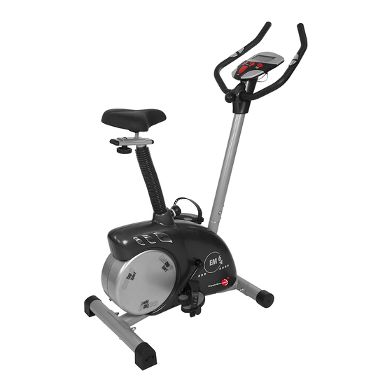
- Page 1 Heimsport-Trainingsgerät EM 6 98062 - (Schwarz) Montage- und Bedienungsanleitung für Bestell-Nr. 98062 A - (Silber) Assembly and exercise instructions for Order No. 98063 - (Rot) Notice de montage et d’utilisation du No. de commande Montage- en bedieningshandleiding voor Bestellnummer Инструкция по монтажу и эксплуатации...
-
Page 2: Wichtige Empfehlungen Und Sicherheitshinweise
Inhaltsübersicht Contents Page 1. Wichtige Empfehlungen und Sicherheitshinweise Seite 2. Einzelteileübersicht Seite 3. Stückliste Seite 4 - 5 4. Montageanleitung mit Explosionsdarstellungen Seite 6 - 8 5. Computeranleitung Seite Sommaire Page 6. Trainingsanleitung Seite 10 Sehr geehrte Kundin, sehr geehrter Kunde Wir gratulieren Ihnen zum Kauf dieses Heimsport-Trainingsgerätes und Inhoudsopgave Pagina 34... -
Page 4: Stückliste - Ersatzteilliste
Nach Öffnen der Verpackung bitte kontrollieren, ob alle Teile ent- Stückliste - Ersatzteilliste sprechend der nachfolgenden Stückliste vorhanden sind. Ist dies EM 6 Best.-Nr. 98062, 98062A, 98063 der Fall, können Sie mit dem Zusammenbau beginnen. Technische Daten: Stand: 01. 10. 2008... - Page 5 Stückliste - Ersatzteilliste EM 6 Best.-Nr. 98062, 98062A, 98063 Abbildungs- Bezeichnung Abmessung Menge Montiert an ET-Nummer Stück Abbildungs Nr. Spannbügel 33-9806210-SI Schraube M8x20 1+39 39-10095-CR Schraube M10x35 35+39 39-10131 Schraube 4.5x25 19L+19R 36-9825339-BT Schraube 5x15 19+28 39-9903-SW Distanzstück 36-9806218-BT Schraube...
- Page 6 Montageanleitung Montageanleitung Entnehmen Sie alle Einzelteile der Verpackung, legen diese auf den Boden und kontrollieren die Vollzähligkeit anhand der Stückliste dieser Montage- und Bedienungsanleitung. Zu beachten ist dabei, dass einige Teile direkt mit dem Grundgestell verbunden sind und vormontiert wurden. Des Weiteren sind auch einige andere Einzelteile schon zu Einheiten Zusammengefügt worden.
- Page 7 Schritt 4: Montage des Lenkers (6) am Stützrohr (60). 1. Führen Sie den Lenker (6) zur geöffneten Lenkeraufnahme am Stützrohr (60) und schließen Sie diese über den Lenker (6). 2. Stecken Sie eine Unterlegscheibe (8) auf die Sterngriffschraubeschraube (9) und befestigen Sie damit in gewünschter Position den Lenker (6) am Stützrohr (60).
- Page 8 Schritt 7: Montage des Computers (62) am Stützrohr (60). 1. Stecken Sie den Stecker des Computerkabelstranges (63), der oben aus dem Lenkerstützrohr (60) ragt, in die auf der Rückseite des Computers (62) befi ndliche Buchse. 2. Schieben Sie den Computer auf die dafür vorgesehene Platte des Lenkerstützrohres (60), und schrauben Sie ihn mit den Schrauben (61) fest.
- Page 9 TRAININGSCOMPUTER sition zurückgesetzt. „E“ : Mit der Eingabe - und Bestätigungstaste (N) wechselt man von einem Eingabefeld zum nächsten. Die jeweils angewählte Funktion blinkt. Mit der +/- Taste O + P geben Sie die Werte ein und durch erneutes Drücken der „E“ –Taste werden diese bestätigt. Gleichzeitig springt die Blinkanzeige in das nächste Eingabe feld.
- Page 10 angezeigt. Die Veränderung wirkt sich auf die momentane und folgende PULSOBERGRENZE/BMI/ALTER: Verfügbar in den Programmen 1- 8 ( nicht in Programm 10 –12). Sobald Sie Ihr Alter eingeben, errechnet der Zeit-Position aus. Die Höhe der Balken zeigt die Belastung an, nicht ein Computer einen Warn-Pulswert, den Sie keinesfalls überschreiten sollten Geländeprofi...
- Page 11 P7 (Intervall) P8 (U1 - U4) P9 (Watt-Drehzahlunabhängig) 1. Handpulsmessung: dieses Programm entspricht den Funktionen eines normalen Heimtrainers. So werden hier die Zeit , die Geschwindigkeit/U/min, die Entfernung, die Im linken und rechten Lenkergriffteil ist je eine Metallkontaktplatte, die Watt/Kjoule, der aktuelle Puls und der Warnpuls permanent im Anzeigefeld Sensoren, eingelassen.
- Page 12 Garantiebestimmungen Die Garantie beginnt mit dem Rechnungs- bzw. Auslieferdatum und beträgt 24 Monate. Während der Garantiezeit werden eventuelle Mängel kostenlos beseitigt. Bei Feststellung eines Mangels sind Sie verpfl ichtet diesen unverzüglich dem Hersteller zu melden. Es steht im Ermessen des Herstellers die Garantie durch Ersatzteilversand oder Reparatur zu erfüllen.
-
Page 13: Important Recommendations And Safety Instructions
Contents 1. Summary of Parts Page 3 - 4 2. Important Recommendations and Safety Information Page 15 3. Parts List Page 16 - 17 4. Assembly Instructions With Exploded Diagrams Page 18 - 20 5. Computer instructions Page 21 - 24 6. - Page 14 Please check after opening the packing that all the parts shown in Parts List – Spare Parts List the following parts lists are there. Once you are sure that this is the EM 6 Order No. 98062, 98062A, 98063 case, you can start assembly. Technical data: Issue: 01.
- Page 15 Parts List – Spare Parts List EM 6 Order No. 98062, 98062A, 98063 Illustration imensions Quantity Attached to ET number signation illustration No. Idle bracket 33-9806210-SI Screw M8x20 1+39 39-10095-CR Screw M10x35 35+39 39-10131 Screw 4.5x25 19L+19R 36-9825339-BT Screw 5x15...
- Page 16 Assembly Instructions Remove all the separate parts from the packaging, lay them on the fl oor and check that all are there on the basis of the packing list in these instructions for assembly and use. Please note that a number of parts have been connected directly to the main frame and preassembled.In addition, there are several other individual parts that have been attached to separate units.
- Page 17 Step 4: Attach the handlebar (6) at handlebar support (60). 1. Guide the preassembled handlebar unit (6) through the upper part of the handlebar post (60) and close the bracket of handlebar holder. 2. Screw the handlebar (6) in desired position at the handlebar post (60) with washer (8) and handlebar screw (9).
- Page 18 Step 7: Attach the computer (62) at handlebar support (60). 1. Push the plug of the connecting cable (4) projecting from the handlebar support (60) into the associated socket of the computer (62). 2. Place the computer on the plate provided for it on the handlebar support (60) and attach it with the screws (61).
- Page 19 ABOUT DISPLAY TRAININGSCOMPUTER A. START: Indicates the program selected has started. B. STOP: Indicates the program selected has stopped and users are free to change the programs and the value of functions applied. C. PROGRAM: Indicates the programs selected from PROGRAM 1 to PROGRAM 13.
- Page 20 Operating Ranges Please note that only 1 value of TIME or DISTANCE can be adjusted. Both adjustments do not exist at the same time. For example, the value of DISTANCE is „0.0“ while the value of TIME is adjusted to be any number except „00:00“.
- Page 21 E. Body Types: There are 9 body types divided according to the FAT% calculated. Type 1 85%(220 – age). So, if the heart rate detected equals to or greater than the is from 5% to 9%. Type 2 is from 10% to 14%. Type 3 is from 15% to 19%. TARGET H.R., the value of HEART RATE will keep fl...
-
Page 22: Training Instructions
Training instructions You must consider the following factors in determining the amount of training effort required in order to attain tangible physical and health benefi ts: 1. Intensity: The level of physical exertion in training must exceed the level of normal exertion without reaching the point of breathlessness and / or exhaustion. -
Page 23: Recommandations Importantes Et Consignes De Sécurité
Sommaire 1. Aperçu des pièces Page 2. Recommandations importantes et règles de sécurité Page 3. Nomenclature Page 26 - 27 4. Notice de montage avec écorchés Page 28 - 30 5. Manuel d’utilisation du calculateur électronique Page 31 - 34 6. -
Page 24: Dimensions
Après avoir ouvert l’emballage, veuillez contrôler s’il y a toutes les Liste des pièces- Liste des pièces de rechange pièces conformément à la liste suivante. Si c’est le cas, vous pouvez EM 6 N° de commande 98062, 98062A, 98063 commencer l’assemblage. Caractéristiques techniques : Version du : 01/ 10/ 2008 Si une pièce n’est pas correcte, s’il manque une pièce ou si vous... - Page 25 Liste des pièces- Liste des pièces de rechange EM 6 N° de commande 98062, 98062A, 98063 Schéma Désignation Dimensions Quantité Monté sur Numéro ET n° en mm Unités schéma n° Étrier de serrage 33-9806210-SI M8x20 1+39 39-10095-CR M10x35 35+39 39-10131 4.5x25...
- Page 26 Notice de montage Sortez toutes les pièces de l’emballage, posez-les sur le sol et contrôlez si rien ne manque en vous basant sur la nomenclature de cette Notice de montage et d’utilisation. Il faut tenir compte du fait que certaines pièces ont été...
- Page 27 Etape n° 4: Montage du guidon (6) 1. Dirigez le guidon (6) vers le logement ouvert du guidon, au niveau du tube support (60) et fermez-le au-dessus du guidon (66). 2. Placez une rondelle (8) sur la vis à oreilles (9) afi n de pouvoir fi xer le guidon (6) dans la position souhaitée, au niveau du tube support (60).
- Page 28 Etape n° 7: Montage de l’ordinateur (62) 1. Branchez le connecteur du faisceau de câbles (63) du calculateur qui dépasse du tube de support du guidon (60) dans la prise qui se trouve au dos du calculateur (62). 2. Insérez l’ordinateur sur la plaque prévue à cet effet sur le tube d’appui du guidon (60) et vissez le calculateur (62) avec des vis (61).
- Page 29 Guide d’utilisation de l’ordinateur de saisie à la suivante. La fonction sélectionnée clignote. Les touches 0 + P + / - vous permettent d’introduire des valeurs et la touche « E », de les confi rmer. . Simultanément, la zone de donnée suivant clignote. «...
-
Page 30: Les Valeurs Établies Et Affi Chées Ne Sont En Aucun Cas
LIMITE SUPERIEURE DES PULSATIONS/BMI/ÂGE Disponible dans les Les valeurs établies et affi chées ne sont en aucun cas programmes 1 à 8 (mais pas 10 à 12). adaptées à une évaluation médicale. Dès que vous avez introduit votre âge, l’ordinateur calcule une valeur de A. -
Page 31: Sélection Du Programme
A. Sélection du programme: Programme 1 (Manuel) Programme 2 (ascendant - descendant) Programme3 (vallée) Programme 4 (Fitness) Programme 5 (Rampe) Programme 6 (Montagne) Programme 7 (Intervalle) Programme 8 (Utilisateur U 1-U4) Programm 9 (watt-indépendamment du nombre de tours) Programme 10 (60% max. de puls.) Programme 11 (75% max. - Page 32 Mesure des pulsations1. Mesure des pulsations à la poignéeLes poig- nées droite et gauche comportent chacune un capteur (pièces de contact métalliques.) Connectez le câble à la prise 21 de l’ordinateur. Attention, veillez à ce que la paume de vos mains repose simultanément sur les capteurs, avec une pression normale.
-
Page 33: Recommandations Pour L'entraînement
Recommandations pour l’entraînement Les facteurs ci-après doivent être pris en compte pour la détermination de l’entraînement indispensable afi n d’améliorer concrètement son physique et sa santé: 1. Intensité: L’entraînement n’aura d’effets positifs que si les efforts déployés dépassent ceux de la vie quotidienne, mais sans être hors d’haleine et/ou se sentir épui- sé. -
Page 34: Belangrijke Aanbevelingen En Veiligheids Instructies
Inhoudsopgave 1. Overzicht van de losse delen pagina 2. Belangrijke aanbevelingen en veiligheidsinstructies pagina 36 3. Stuklijst pagina 37 - 38 4. Montagehandleiding met explosietekeningen pagina 39 - 41 5. Handleiding bij de computer pagina 42 - 45 6. Trainingshandleiding pagina 46 Geachte klant Wij willen u van harte gelukwensen met de aanschaf van uw hometrainer en... - Page 35 Controleer na het openen van de verpakking a.u.b. aan de hand van de onderstaande stuklijst of alle onderdelen aanwezig zijn. Wanneer EM 6 best.nr. 98062, 98062A, 98063 dit het geval is, kunt u met de montage beginnen. Technische specifi catie: Stand: 01.
- Page 36 Stuklijst - reserveonderdelenlijst EM 6 best.nr. 98062, 98062A, 98063 Afbeeldings- Beschrijving Afmetingen Aantal Gemonteerd aan ET-nummer stuks afbeeldingsnr. Spanbeugel 33-9806210-SI Schroef M8x20 1+39 39-10095-CR Schroef M10x35 35+39 39-10131 Schroef 4.5x25 19L+19R 36-9825339-BT Schroef 5x15 19+28 39-9903-SW Afstandsstuk 36-9806218-BT Schroef M5x12...
- Page 37 Montagehandleiding Neem alle losse onderdelen uit de verpakking, leg deze op de grond en controleer aan de hand van de stuklijst uit de montageen bedieningshandleiding of alle onderdelen aanwezig zijn. Hierbij moet er op worden gelet dat een aantal onderdelen rechtstreeks met het onderstel zijn verbonden en voorgemonteerd zijn.
- Page 38 Stap 4: Montage van de stuur (6) 1. Voer het stuur (6) door de geopende stuurhouder op de stuurframe (60) en sluit u deze over het stuur(6). 2. Plaatst u een ring (8) op de vleugelschroef (9) en hiermee bevestigd u het stuur (6) in de gewenste positie op stuurbuis (60).
- Page 39 Stap 7: Montage van de computer (62) 1. Steek de stekker van de computerkabel (63), die aan de bovenzijde uit de stuurbuis (60) steekt, in de bus aan de achterzijde van de computer (62). 2. Schuif de computer (62) op de daarvoor voorziene plaat van de stuursteunbuis (60) schroef de computer (62) m.b.v.
- Page 40 • Toetsen TRAININGSCOMPUTER In totaal 6 toetsen: START/STOP (S), INVOER (E), FUNCTIE (U1 - U4), OM- HOOG (+), OMLAAG (-), en TEST (Test). „S“: start van de training of onderbreking van de training in het gekozen programma. In de modus „STOP“ is het STOP-display J verlicht. De compu- ter begint pas te tellen wanneer voordien de toets „S“...
- Page 41 KJOULE/WATT/BMR: door middel van de gemiddelde waarden berekent hogere balken=hogere trapweerstand de computer de Joule, die in KJoule aangegeven worden. Om de bindende lagere balken= lagere trapweerstand maateenheid voor energie „Joule“ in de algemeen gebruikelijke vermelding elk balkensegment houdt 2 waarden in „Calorieën“...
- Page 42 A. Programmakeuze: Programma 1 (handmatig) Programma 2 (omhoog - omlaag) Programma 3 (dal) Programma 4 (fi tness) Programma 5 (platform) Programma 6 (berg) Programma 7 (interval) Programma 8 (gebruiker U1 - U4) Programma 9 (watt-toerentalonafhankelijk) Programma 10 (60% max. polsslag) Programma 11 (75% max.
- Page 43 POLSSLAGMETING: 1. Handpulsmeting: In het linkse en rechtse stuurgedeelte is telkens een metalen contactplaat, de voelers, voorzien. Verbind de kabel met de aansluiting 3 op de computer. Gelieve erop te letten dat steeds beide handpalmen gelijktijdig met normale kracht op de voelers liggen. Zodra er een polsslag volgt, knippert er een hart naast het polsslagdisplay F.
- Page 44 Trainingshandleiding De onderstaande factoren moeten in acht worden genomen bij het bepalen van de benodigde training voor het bereiken van een merkbare verbetering van uw fi guur en gezondheid: 1. Intensiteit: De mate van lichamelijke belasting bij de training moet de normale belasting overschrijden, zonder dat u daarbij buiten adem en/of uitgeput raakt.
-
Page 45: Обзор Содержания
Обзор содержания Важные рекомендации и указания по безопасности ctp. 2. Обзор отдельных деталей стр. 3. Спецификация стр. 48 - 49 4. Руководство по сборке с отдельными иллюстрациями стр. 50 - 52 5. Руководство по использованию компьютера стр. 53 - 56 6. - Page 46 Сняв упаковку, проверьте по списку, все ли детали на месте. Спецификация - Список запасных частей Если все в порядке, то можно начинать сборку. Если какой- EM 6 № заказа 98062, 98062A, 98063 нибудь агрегат не в порядке или отсутствует, обращайтесь к Технические характеристики...
- Page 47 Спецификация - Список запасных частей EM 6 № заказа 98062, 98062A, 98063 № Наименование Размеры в мм Кол-во Монтируется на № ЕТ-№ картинки штук Натяжной элемент 33-9806210-SI Болт M8x20 1+39 39-10095-CR Болт M10x35 35+39 39-10131 Болт 4.5x25 19L+19R 36-9825339-BT Болт...
-
Page 48: Руководство По Монтажу
Руководство по монтажу Пожалуйста, выньте все отдельные части из коробки и проверьте их на комплектность в соответствии со спецификацией. Примите во внимание, что некоторые части предварительно смонтированы. Шаг 1: Монтаж ножек (31+55) на основную раму (28) 1. Смонтируйте переднюю ножку (55) с транспортировочными роликами (54) на... - Page 49 Шаг 4: Монтаж руля (6) на опорную трубу руля (60) 1. Подведите руль (6) к открытому креплению руля на опорной трубу руля (60) и закройте его над рулем (6). 2. Наденьте подкладную шайбу (8) на грибковый болт (9) и прикрутите ими...
- Page 50 Шаг 7: Монтаж компьютера (62) на опорную трубу руля (60) 1. Вставьте штекер компьютерного кабеля (63), выходящий сверху из опорной трубы руля (60), в соответствующее гнездо, находящееся на обратной стороне компьютера (62). 2. Приложите компьютер на держатель компьютера, находящийся на опорной...
- Page 51 TRAININGSCOMPUTER Выключение: Компьютер отключается самостоятельно если более 4 Мин. Аппаратом не пользовались После окончания тренировки необходимо вытащить штекер из гнезда. • Клавиши Всего 6 Клавиш: START(Старт)/STOP(Стоп) (S), EINGABE(Ввод) (E), (U1 - U4), AUF(Вверх) (+), AB(Вниз) (-), and TEST(Тест) (Test). „S“: Старт или остановка тренировки в выбранной программе. В STOPP(Стоп)- модусе...
- Page 52 KJOULE/WATT/BMR, КИЛОДЖОУЛЬ/ВАТТ/ BMR : В индикаторе Выше балка = Выше нагрузка указываются только килоджоули. Для пересчета джоулей в калории Низкая балка = Низкая нагрузка и обратно применяйте формулу: 1 джоуль = 0,239 калорий, или Каждый сегмент балки содержит 2-е 1калория = 4,186 дж. Введение величин в джоулях невозможен потому величины...
- Page 53 Выбор программ: Программа 1 (уст.вручную) Программа 2 (Вверх - Вниз) Программа3 (Ущелье) Программа 4 (Фитнес) Программа 5 (Рампа) Программа 6 (Г ора) Программа 7 (Интервал) Программа 8 Программа 9 (пользователь U1-U4) (Ватт-нез.от оборотов) Программа 10 (60% Макс. пульс) Программа 11 (75% Макс. пульс) Программа 12 (85% Макс. пульс) Программа...
- Page 54 ИЗМЕРЕНИЕ ПУЛЬСА: 1. Ручное имерение пульса: В левой и правой части руля находятся сенсоры в виде металлических пластин от которых отходит кабель. Соедените кабель с гнездом 21 на компьютере. Измерение пульса происходит только после одновременного наложения рук на сенсоры. О том что происходит считывание...
- Page 55 ИНСТРУКЦИЯ ПО ТРЕНИРОВКЕ Вы должны учитывать следующие факторы, чтобы определить верные параметры тренировок для достижения ощутимых физических результатов и пользы для здоровья. Интенсивность Уровень физических нагрузок при тренировках должен превышать уровень нормальных физических нагрузок, но вы не должны задыхаться и сильно переутомляться. Удобной мерой эффективности тренировки...
- Page 56 Service / Hersteller Bei Reklamationen, notwendigen Ersatzteilbestellungen oder © by Top-Sports Gilles GmbH Reparaturen wenden Sie sich bitte an unsere Service Abteilung. D-42551 Velbert (Germany) Service: Top-Sports Gilles GmbH Tel.: +49 (0)2051/6067-0 Friedrichstrasse 55 info@christopeit-sport.com Fax: +49 (0)2051/6067-44 D - 42551 Velbert http://www.christopeit-sport.com...