Publicité

Les langues disponibles
  • FR

Les langues disponibles

  • FRANÇAIS, page 22

Liens rapides

Operating Instructions/Bedienungsanleitung/
Before operating this product, please read the instructions carefully and save this
manual for future use.
Bitte lesen Sie diese Bedienungsanleitung vor der Inbetriebnahme dieses Produkts
aufmerksam durch, und bewahren Sie sie für späteres Nachschlagen auf.
Avant d'utiliser l'appareil, lire attentivement ce mode d'emploi, et le conserver à
des fins de référence ultérieure.
Prima di far funzionare questo prodotto, leggere attentamente le istruzioni e
conservare questo manuale per riferimenti futuri.
Antes de utilizar este producto, lea cuidadosamente las instrucciones y guarde
este manual por si tiene que utilizarlo en el futuro.
このたびは、 " パナソニック製品 " をお買い上げいただき、まことにありがとうございます。
■ 取扱説明書をよくお読みのうえ、正しく安全にお使いください。
■ ご使用前に「安全上のご注意」 ( 2 〜 3 ページ)を必ずお読みください。
■ 保証書は「お買い上げ日・販売店名」などの記入を確かめ、取扱説明書とともに大切に
保管してください。
保証書別添付
FJ0909AT2062 -FJ
Printed in Japan
Mode d'emploi/Istruzioni per l'uso/
Instrucciones de funcionamiento/
VF Interface Box/VF Interface Box/
VF interface box/Interfaz de VF/
AG-YA500G
Model No.
製造番号は、品質管理上重要なものです。
製品本体と保証書の製造番号をお確かめください。
Boîtier d'interface VF/
VF インターフェースボックス
取扱説明書
VQT2H48-1

Publicité

Table des Matières
loading

Sommaire des Matières pour Panasonic AG-YA500G

  • Page 1 VF Interface Box/VF Interface Box/ Boîtier d’interface VF/ VF interface box/Interfaz de VF/ VF インターフェースボックス AG-YA500G Model No. Before operating this product, please read the instructions carefully and save this manual for future use. Bitte lesen Sie diese Bedienungsanleitung vor der Inbetriebnahme dieses Produkts aufmerksam durch, und bewahren Sie sie für späteres Nachschlagen auf.
  • Page 2: Read This First

    English Read this first! WARNING: To reduce the risk of fire or electric shock, do not expose this equipment to rain or moisture. To reduce the risk of fire or electric shock, keep this equipment away from all liquids. Use and store only in locations which are not exposed to the risk of dripping or splashing liquids, and do not place any liquid containers on top of the equipment.
  • Page 3 Read this first! (Continued) FCC Note (USA): This equipment has been tested and found to comply with the limits for a class B digital device, pursuant to Part 15 of the FCC Rules. These limits are designed to provide reasonable protection against harmful interference in a residential installation. This equipment generates, uses, and can radiate radio frequency energy and, if not installed and used in accordance with the instruction manual, may cause harmful interference to radio communications.
  • Page 4 Read this first ! (continued) EMC NOTICE FOR THE PURCHASER/USER OF THE APPARATUS 1. Applicable standards and operating environment (For Europe) The apparatus is compliant with: standards EN55103-1 and EN55103-2 electromagnetic environments E1, E2, E3, and E4. 2. Pre-requisite conditions to achieving compliance with the above standards <1>...
  • Page 5: Table Des Matières

    Thank you for purchasing the VF Interface Box AG-YA500G (“this unit” hereafter). Contents Read this first! ................. E-1 Supplied Accessories ..............E-4 Features ................... E-4 System Diagram ................E-5 Parts and their functions ..............E-6 Mounting to the Camera recorder..........E-7 Basic Operations ................
  • Page 6: System Diagram

    Viewfinder AJ-VF15BP/E AJ-VF20WBP/E AG-VF11G AG-EC4G AJ-HVF21G AJ-CVF100G AG-BS300P/E Lens AG-CA300G Camera recorder * * Compatible camera recorders AG-YA500G AG-HPX500/502 AJ-HPX3700G AJ-HPX2700G CAM VF AJ-HPX3000G CA VF AJ-HPX2000/2100 CAM LENS LENS AJ-HDX900P/E <Notes> This unit needs to set the viewfinder type (HD/ LCD SD) connected via the menu of the base station (AG-BS300P/E, option).
  • Page 7: Parts And Their Functions

    Parts and their functions CAM VF CA VF CAM LENS LENS 1. LENS connector (12 pins) This is a connector to input the signal from the lens. Connect with the connector on the lens. 2. CAM LENS c able This is a connector to output the signal from the lens to the camera recorder.
  • Page 8: Mounting To The Camera Recorder

    Mounting to the Camera recorder Confirm the supplied accessories. Mount the mounting bracket to the camera recorder using the two included Mount the mounting bracket to the (8 mm) mounting screws. adjustment bracket using the two When using the microphone holder included mounting screws (8 mm) so (AJ-MH800G, optional) together with this that this unit will be horizontal when it is...
  • Page 9: Basic Operations

    Basic Operations Switching of the video signals is performed by pressing the RET switch on the lens or the RET switch on the camera adapter. Return video is output from this unit while the RET switch is pressed. Also, if there is a tally signal either from the camera recorder or the base station, it is also output from this unit, and the tally LED on the viewfinder can be turned on.
  • Page 10 AG-CA300G Camera RET input signal Image displayed on the VF OUT recorder VF System Camera model format to the AG- AJ-HVF21G/AG-VF11G/ connector connector BS300P/E AJ-CVF100G signal signal HD SDI Cannot use since HD HD SDI cannot be video cannot be transmitted.
  • Page 11: Specifications

    Specifications [General] [I/O Section] LENS: Input Round 12 pin DC + 5.6 V, 0.06 A CAM LENS: DC - 5.6 V, 0.06 A Round 12 pin CAM VF: Round 20 pin indicates safety information. Round 20 pin Dimensions (W a H a D): CA VF: 113 mm a 60 mm a 41 mm D-Sub 15 pin...
  • Page 12 GERMAN Bitte lesen! WARNUNG: Zur Reduzierung der Gefahr eines Brands oder elektrischen Schlags dieses Gerät weder Nässe noch Feuchtigkeit aussetzen. Zur Reduzierung der Gefahr eines Brands oder elektrischen Schlags muss dieses Gerät von allen Flüssigkeiten ferngehalten werden. Vermeiden Sie Gebrauch und Lagerung des Gerätes an orten, an denen die Gefahr besteht, dass es mit Flüssigkeiten betropft oder bespritzt wird, und stellen Sie keine Flüssigkeitsbehälter auf das Gerät.
  • Page 13 Bitte lesen ! (Fortsetzung) EMV-HINWEIS FÜR DEN KÄUFER/ANWENDER DES GERÄTS 1. Anwendbare Standards und Betriebsumgebung (Für Europe) Dieses Gerät entspricht: Standards EN55103-1 und EN55103-2 elektromagnetische Umgebungen, E1, E2, E3 und E4. 2. Erforderliche Bedingungen zur Einhaltung der oben genannten Standards <1>...
  • Page 14: Mitgeliefertes Zubehör

    Vielen Dank, dass Sie die VF Interface Box AG-YA500G gekauft haben (nachfolgend “dieses Gerät”). Inhalt Bitte lesen!..................G-1 Mitgeliefertes Zubehör..............G-3 Funktionen..................G-3 System Diagram ................G-4 Teile und ihre Funktionen..............G-5 Montage an den Kamerarecorder ...........G-6 Basisbetrieb..................G-7 Spezifikationen.................G-9 Mitgeliefertes Zubehör Montageschrauben Montageschrauben (12 mm) a 2...
  • Page 15: System Diagram

    Sucher AJ-VF15BP/E AJ-VF20WBP/E AG-VF11G AG-EC4G AJ-HVF21G AJ-CVF100G AG-BS300E Objektiv AG-CA300G Kamerarecorder * * Kompatible Kamerarecorder AG-YA500G AG-HPX500E AJ-HPX3700G AJ-HPX2700G CAM VF AJ-HPX3000G CA VF AJ-HPX2100E CAM LENS LENS AJ-HDX900E <Hinweise> Dieses Gerät muss den Suchertyp (HD/LCD SD) einstellen, der durch das Menü der Basisstation (AG-BS300E, optional) verbunden wird.
  • Page 16: Teile Und Ihre Funktionen

    Teile und ihre Funktionen CAM VF CA VF CAM LENS LENS 1. LENS-Anschluss (12 Kontakte) Dies ist ein Anschluss, um das Signal vom Objektiv einzuspeisen. Schließen Sie ihn an den Anschluss des Objektivs an. 2. CAM LENS-Kabel Dies ist ein Anschluss, um das Signal vom Objektiv an den Kamerarecorder auszugeben.
  • Page 17: Montage An Den Kamerarecorder

    Montage an den Kamerarecorder Bestätigen Sie das Mitgeliefertes Montieren Sie die Montageklammer an Zubehör. den Kamerarecorder, indem Sie die zwei mitgelieferten Montageschrauben Montieren Sie die Montageklammer an (8 mm) verwenden. die Justierklammer, indem Sie die zwei Wenn Sie den Mikrofonhalter mitgelieferten Montageschrauben (8 (AJ-MH800G, optional) zusammen mit mm) verwenden, sodass dieses Gerat...
  • Page 18: Basisbetrieb

    Basisbetrieb Das Ausschalten des Videosignals wird durch das Drücken des RET-Schalters am Objektiv oder des RET-Schalters am Kameraadapter durchgeführt. Return Video wird von diesem Gerät ausgegeben, während der RET-Schalter gedrückt wird. Es wird auch von diesem Gerät ausgegeben, wenn es ein Zählersignal, entweder vom Kamerarecorder oder der Basisstation, gibt und die Zähler-LED-Anzeige am Sucher eingeschaltet werden kann.
  • Page 19 AG-CA300G Kamerarecorder Angezeigte Bilder auf dem Eingangssyignalfor System Kameramodul VF OUT- AJ-HVF21G/AG-VF11G/ mat an den AG- Anschlusssignal Anschlusssignal AJ-CVF100G BS300E Kann nicht verwendet HD SDI kann werden, da HD-Video HD SDI nicht übertragen nicht übertragen werden. werden kann. SD SDI SD COMPONENT AG-HPX500E COMPONENT...
  • Page 20: Spezifikationen

    Spezifikationen [Allgemein] Eingang DC + 5,6 V, 0,06 A DC - 5,6 V, 0,06 A ist die Sicherheitsinformation. Abmessungen (B a H a T): 113 mm a 60 mm a 41 mm (außer vorstehende Teile) Gewicht: Ca. 410 g Betriebstemperatur: 0 °C bis 40 °C Lagertemperatur: -20 °C bis 60 °C...
  • Page 21 Benutzerinformationen zur Entsorgung von elektrischen und elektronischen Geräten (private Haushalte) Dieses Symbol auf Produkten und/oder begleitenden Dokumenten bedeutet, dass verbrauchte elektrische und elektronische Produkte nicht mit gewöhnlichem Haushaltsabfall vermischt werden sollen. Bringen Sie zur ordnungsgemäßen Behandlung, Rückgewinnung und Recycling diese Produkte zu den entsprechenden Sammelstellen, wo sie ohne Gebühren entgegengenommen werden.
  • Page 22: Lire Ces Informations En Premier

    FRANÇAIS Lire ces informations en premier ! AVERTISSEMENT: Pour réduire tout risque d’incendie ou de choc électrique, évitez d’exposer cet appareil à la pluie ou à l’humidité. Pour réduire tout risque d’incendie ou de choc électrique, éloignez l’appareil des liquides. Utiliser et ranger uniquement dans un endroit ne risquant pas de recevoir des gouttes ou d’être aspergé...
  • Page 23: Conditions Requises Pour Obtenir La Conformité Aux Normes Ci-Dessus

    Lire ces informations en premier ! (suite) NOTE D’INFORMATION SUR LA CEM POUR L’ACHETEUR/ UTILISATEUR DE L’APPAREIL 1. Normes applicables et environnement de fonctionnement (Pour l’Europe) L’appareil est conforme: aux normes EN55103-1 et EN55103-2 aux environnements électromagnétiques E1, E2, E3 et E4 2.
  • Page 24: Accessoires Fournis

    Nous vous remercions d’avoir acheté le Boîtier d’interface VF AG-YA500G (appelé “cette unité” ci-après). Contenu Lire ces informations en premier ! ..........F-1 Accessoires fournis.................F-3 Caractéristiques ................F-3 Diagramme du système..............F-4 Pièces et leurs fonctions..............F-5 Montage sur le caméscope .............F-6 Opérations de base................F-7 Spécifications...................F-9...
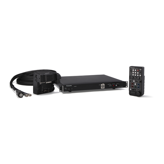
  • Page 25: Diagramme Du Système

    Viseur AJ-VF15BP/E AJ-VF20WBP/E AG-VF11G AG-EC4G AJ-HVF21G AJ-CVF100G AG-BS300P/E Objectif AG-CA300G Caméscope * * Caméscopes compatibles AG-YA500G AG-HPX500/502 AJ-HPX3700G AJ-HPX2700G CAM VF AJ-HPX3000G CA VF AJ-HPX2000/2100 CAM LENS LENS AJ-HDX900P/E <Remarques> Cette unité nécessite le réglage du type de viseur (HD/LCD SD) connecté par l’intermédiaire du menu de la station de base (AG-BS300P/E, en option).
  • Page 26: Pièces Et Leurs Fonctions

    Pièces et leurs fonctions CAM VF CA VF CAM LENS LENS 1. Connecteur OBJECTIF (12 broches) Il s’agit d’un connecteur pour entrer le signal provenant de l’objectif. Connectez- le au connecteur sur l’objectif. 2. Câble CAM OBJECTIF Il s’agit d’un connecteur pour transmettre le signal provenant de l’objectif au caméscope.
  • Page 27: Montage Sur Le Caméscope

    Montage sur le caméscope Confirmez les accessoires fournis. Montez le support de montage sur le camescope en utilisant les deux vis de Montez le support de montage sur le montage incluses (8 mm). support de reglage en utilisant les deux Lors de l’utilisation du support pour vis de montage incluses (8 mm) de microphone (AJ-MH800G, en option)
  • Page 28: Opérations De Base

    Opérations de base La commutation des signaux vidéo peut être effectuée en pressant le commutateur RET sur l’objectif ou le commutateur RET sur l’adaptateur pour caméra. La vidéo en retour est transmise à partir de cette unité pendant que le commutateur RET est pressé. En outre, même s’il y a un signal d’enregistrement provenant soit du caméscope, soit de la station de base, celui-ci est également transmis à...
  • Page 29 AG-CA300G Format du signal Signal du Image affichée sur Modèle de Signal du Système d’entrée RET connecteur VF l’AJ-HVF21G/AG-VF11G/ caméra connecteur à l’AG-BS300P/E caméscope AJ-CVF100G VF OUT Ne peut être utilisée HD SDI ne peut étant donné que la HD SDI être transmis.
  • Page 30: Spécifications

    Spécifications [Générales] Entrée CC + 5,6 V, 0,06 A CC - 5,6 V, 0,06 A Informations concernant la sécurité. Dimensions (L a H a P): 113 mm a 60 mm a 41 mm (4,4 pouces a 2,4 pouces a 1,6 pouces) (à...
  • Page 31 Informations relatives à l’évacuation des déchets, destinées aux utilisateurs d’appareils électriques et électroniques (appareils ménagers domestiques) Lorsque ce symbole figure sur les produits et/ou les documents qui les accompagnent, cela signifie que les appareils électriques et électroniques ne doivent pas être jetés avec les ordures ménagères. Pour que ces produits subissent un traitement, une récupération et un recyclage appropriés, envoyez-les dans les points de pré-collecte désignés, où...
  • Page 32 ITALIANO Leggere prima quanto segue! AVVERTIMENTO: Per ridurre il rischio d’incendio o di folgorazione, non esporre questo prodotto alla pioggia o all’umidità. Per ridurre il rischio d’incendio o di folgorazione, mantenere questo prodotto lontano da ogni tipo di liquido. Usarlo e conservarlo soltanto in luoghi che non siano esposti a gocciolamenti o spruzzi di liquidi, e non mettervi sopra recipienti di liquidi.
  • Page 33 Leggere prima quanto segue! (continua) AVVISO EMC PER L’ACQUIRENTE/UTENTE DELL’APPARATO 1. Standard applicabili e ambiente operativo (Per l’Europa) L’apparato è conforme a: standard EN55103-1 e EN55103-2 ambienti elettromagnetici delle classi E1, E2, E3 e E4. 2. Prerequisiti essenziali per la conformità agli standard sopra menzionati <1>...
  • Page 34: Accessori Inclusi

    Grazie per aver acquistato una VF interface box AG-YA500G (nel seguito denominata “l’unità”). Sommario Leggere prima quanto segue!............I-1 Accessori inclusi................I-3 Caratteristiche ..................I-3 Schema del sistema.................I-4 Parti e funzioni .................I-5 Montaggio sulla telecamera ............I-6 Operazioni di base ................I-7 Specifiche tecniche................I-9 Accessori inclusi...
  • Page 35: Schema Del Sistema

    Mirino AJ-VF15BP/E AJ-VF20WBP/E AG-VF11G AG-EC4G AJ-HVF21G AJ-CVF100G AG-BS300E Obiettivo AG-CA300G Telecamera * * Telecamere compatibili AG-YA500G AG-HPX500E AJ-HPX3700G AJ-HPX2700G CAM VF AJ-HPX3000G CA VF AJ-HPX2100E CAM LENS LENS AJ-HDX900E <Note> L’unità deve impostare il tipo di mirino (HD/LCD SD) montato attraverso il menu della stazione di base (AG-BS300E, opzionale).
  • Page 36: Parti E Funzioni

    Parti e funzioni CAM VF CA VF CAM LENS LENS 1. Connettore OBIETTIVO (12 pin) È il connettore di ingresso dei segnali dall’obiettivo. Collegarlo al connettore dell’obiettivo. 2. Cavo OBIETTIVO CAM È il connettore che trasmette il segnale dall’obiettivo alla telecamera. Collegarlo al connettore dell’obiettivo della telecamera.
  • Page 37: Montaggio Sulla Telecamera

    Montaggio sulla telecamera Verificare che siano presenti i accessori Montare la staffa di montaggio sulla inclusi. telecamera mediante le due viti di montaggio (8 mm) fornite. Montare la staffa di montaggio sulla Se si utilizza il supporto microfono telecamera mediante le due viti di (AJ-MH800G, opzionale) insieme montaggio (8 mm) fornite in modo tale all’unità, utilizzare le viti di montaggio...
  • Page 38: Operazioni Di Base

    Operazioni di base La commutazione dei segnali video viene effettuata premendo l’interruttore RET situato sull’obiettivo o l’interruttore RET situato sull’adattatore della telecamera. Mentre è premuto l’interruttore RET dall’unità viene trasmesso il video di ritorno. Inoltre, se dalla telecamera o dalla stazione di base è trasmesso un segnale tally, quest’ultimo viene trasmesso anche dall’unità, e il LED tally sul mirino può...
  • Page 39 AG-CA300G Formato del Segnale Immagine visualizzata Modello Segnale Sistema segnale di ingresso connettore sull’AJ-HVF21G/ telecamera connettore RET all’AG-BS300E VF telecamera AG-VF11G/AJ-CVF100G VF OUT Non è possibile Non utilizzabile poiché HD SDI trasmettere non è possibile HD SDI. trasmettere video HD. SD SDI SD COMPONENT AG-HPX500E...
  • Page 40: Specifiche Tecniche

    Specifiche tecniche [Generale] Ingresso DC + 5,6 V, 0,06 A DC - 5,6 V, 0,06 A sono le informazioni sulla sicurezza. Dimensioni (L a H a P): 113 mm a 60 mm a 41 mm (escluse parti sporgenti) Peso: Aprox. 410 g Temperatura d’esercizio: Da 0 °C a 40 °C Temperatura di immagazzinaggio:...
  • Page 41 Informazioni per gli utenti sullo smaltimento di apparecchiature elettriche ed elettroni- che obsolete (per i nuclei familiari privati) Questo simbolo sui prodotti e/o sulla documentazione di accompagnamento significa che i prodotti elettrici ed elettronici usati non devono essere mescolati con i rifiuti domestici generici. Per un corretto trattamento, recupero e riciclaggio, portare questi prodotti ai punti di raccolta designati, dove verranno accettati gratuitamente.
  • Page 42: Lea Esto Primero

    ESPANÕL Lea esto primero ADVERTENCIA: Para reducir el riesgo de producir un incendio o recibir una sacudida eléctrica, no exponga este equipo a la lluvia ni a la humedad. Para reducir el riesgo de incendio o sacudida eléctrica, mantenga este equipo alejado de todos los líquidos.
  • Page 43 Lea esto primero (continuación) AVISO SOBRE CEM PARA EL COMPRADOR/USUARIO DEL APARATO 1. Normas aplicables y ambiente de funcionamiento (Para Europa) El aparato está conforme con: normas EN55103-1 y EN55103-2 ambientes electromagnéticos E1, E2, E3 y E4. 2. Condiciones previas para conseguir la conformidad con las normas mencionadas <1>...
  • Page 44: Accesorios Suministrados

    Gracias por haber adquirido la interfaz de VF AG-YA500G (en adelante “esta unidad”). Índice Lea esto primero ................S-1 Accesorios suministrados ..............S-3 Características .................S-3 System Diagram ................S-4 Partes y sus funciones ..............S-5 Montaje en la videocámara grabadora ...........S-6 Funcionamiento básico ..............S-7 Especificaciones ................S-9...
  • Page 45: System Diagram

    AJ-VF15BP/E AJ-VF20WBP/E AG-VF11G AG-EC4G AJ-HVF21G AJ-CVF100G AG-BS300P/E Objetivo AG-CA300G Videocámara grabadora * * Videocámaras grabadoras compatibles AG-YA500G AG-HPX500/502 AJ-HPX3700G AJ-HPX2700G CAM VF AJ-HPX3000G CA VF CAM LENS AJ-HPX2000/2100 LENS AJ-HDX900P/E <Notas> En esta unidad debe seleccionarse el tipo de visor (HD/LCD SD) conectado a través del menú...
  • Page 46: Partes Y Sus Funciones

    Partes y sus funciones CAM VF CA VF CAM LENS LENS 1. Conector LENS (12 clavijas) Conector de entrada de la señal del objetivo. Conéctelo con el conector del objetivo. 2. Cable CAM LENS Conector de salida de la señal del objetivo a la videocámara grabadora.
  • Page 47: Montaje En La Videocámara Grabadora

    Montaje en la videocámara grabadora Confirme que tiene los accesorios Instale el soporte de montaje en la suministrados. videocamara grabadora utilizando los dos tornillos de montaje (8 mm) Instale el soporte de montaje en el incluidos. soporte de ajuste utilizando los dos Cuando utilice el portamicrófono tornillos de montaje incluidos (8 mm) de (AJ-MH800G, opcional) junto con esta...
  • Page 48: Funcionamiento Básico

    Funcionamiento básico La conmutación de las señales de vídeo se realiza pulsando el interruptor RET del objetivo o el interruptor RET del adaptador de videocámara. El vídeo de retorno sale de esta unidad mientras se está pulsando el interruptor RET. Además, si hay una señal de tally procedente de la videocámara grabadora o de la estación base, también se extrae de esta unidad, y el LED de tally del visor se puede activar.
  • Page 49 AG-CA300G Señal del Formato de señal Imagen visualizada en el Modelo de Señal del conector VF de Sistema de entrada RET a la AJ-HVF21G/AG-VF11G/ cámara conector la videocámara AG-BS300P/E AJ-CVF100G VF OUT grabadora No se puede No se puede utilizar ya HD SDI transmitir HD que no se puede...
  • Page 50: Especificaciones

    Especificaciones [Generales] Entrada CC + 5,6 V, 0,06 A CC - 5,6 V, 0,06 A indica información de seguridad. Dimensiones (An. a Al. a Pr.): 113 mm a 60 mm a 41 mm (4,4 pulgadas a 2,4 pulgadas a 1,6 pulgadas) (excluidas las partes que sobresalen) Peso: Aprox.
  • Page 51 Información sobre la eliminación para los usuarios de equipos eléctricos y electrónicos usados (particulares) La aparición de este símbolo en un producto y/o en la documentación adjunta indica que los productos eléctricos y electrónicos usados no deben mezclarse con la basura doméstica general. Para que estos productos se sometan a un proceso adecuado de tratamiento, recuperación y reciclaje, llévelos a los puntos de recogida designados, donde los admitirán sin coste alguno.
  • Page 52 日本語 このたびは VF インターフェースボックス AG-YA500G (以下、本機)をお買い上げいただ き、まことにありがとうございました。 目 次 付属品 ..................... J-1 安全上のご注意 ................J-2 特 長 ..................... J-4 システム図 ..................J-4 各部の名称と機能 ................J-5 カメラに取り付けるには ..............J-6 基本動作 ..................J-7 保証とアフターサービス ..............J-9 定 格 ..................... J-10 付属品 固定ビス( 8 mm )...
  • Page 53: 安全上のご注意

    安全上のご注意 必ずお守りください 人への危害、財産の損害を防止するため、必ずお守りいただくことを説明しています。 _ 誤った使い方をしたときに生じる危害や損害の程度を区分して、説明しています。 警告 「死亡や重傷を負うおそれがある内容」です。 注意 「傷害を負うことや、財産の損害が発生するおそれがある内 容」です。 _ お守りいただく内容を次の図記号で説明しています。 してはいけない内容です。 実行しなければならない内容です。 警告 異常、 故障時には直ちに使用を中止する _異常があったときは、 接続プラグを外す [内部に金属や水などの液体、 異物が入ったとき、 落下などで外装ケース が破損したとき、 煙や異臭、 異音などが出たとき] (そのまま使うと、 火災の原因になります。 ) ⇒ 販売店に相談してください。 (次ページに続く) 日 本 語...
  • Page 54 警告(続き) _本機がぬれたり、 水などの液体や異物が入らないようにする (火災の原因になります。 ) ⇒ 雨天 ・ 降雪 ・ 海岸 ・ 水辺での使用は、 特にご注意ください。 ⇒ 機器の上や近くに、 水などの液体が入った花びんなどの容器を置かないでください。 _コードのプラグは、 根元まで確実に差し込む (差し込みが不完全ですと、 発熱による火災の原因になります。 ) ⇒ 傷んだプラグは使用しないでください。 _コードが破損するようなことはしない [傷つける、 加工する、 高温部や熱機器具に近づける、 無理に曲げる、 ねじ る、 引っ張る、 重いものを載せる、 束ねるなど] (傷んだまま使用すると、 火災 ・ ショートの原因になります。 ) ⇒ コードの修理は、 お買い上げの販売店にご相談ください。 _固定ビスは、...
  • Page 55: 特 長

    AJ-VF15BP/E AJ-VF20WBP/E AG-VF11G AG-EC4G AJ-HVF21G AJ-CVF100G AG-BS300 レンズ AG-CA300G * 対応するカメラレコーダー カメラレコーダー * AG-HPX555 AJ-HPX3700G AG-YA500G AJ-HPX2700G AJ-HPX3000G CAM VF AJ-HPX2100 AJ-HDX900 CA VF CAM LENS LENS AJ-HDX400A < ノート > 本機を使用時、接続するビューファインダーの種類( HD/LCD SD )をベースステーショ ン( AG-BS300 ・別売品)側のメニューで設定する必要があります。 AG-BS300 の取扱説...
  • Page 56: 各部の名称と機能

    各部の名称と機能 CAM VF CA VF CAM LENS LENS 1. LENS 端子( 12 ピン) レンズからの信号を入力する端子です。 レンズについているコネクターを接続し ます。 2. CAM LENS ケーブル レンズからの信号をカメラレコーダーへ 出力する端子です。カメラレコーダー本 体のレンズコネクターに接続します。 3. CAM VF ケーブル カメラレコーダーからの信号を入力する 端子です。カメラレコーダー本体の VF コ ネクターに接続します。 4. CA VF ケーブル カメラアダプターからの送り返し映像 ( RET 映像)およびタリー信号を入力す る端子です。カメラアダプターの...
  • Page 57: カメラに取り付けるには

    カメラに取り付けるには 付属の固定ビス( 8 mm ) 2 本を使って、 本機の付属品をご確認ください。 取り付け金具をカメラレコーダーに固 定します。 ご使用になるカメラレコーダーに取り マイクホルダー( AJ-MH800G ・別売品) 付けたとき、本機が水平の位置に来る と本機を同時に使用する場合は、付属の ように付属の固定ビス( 8 mm ) 2 本を 固定ビス( 12 mm )をご使用ください。 使って取り付け金具を調整金具に固定 してください。 固定ビス ご使用になるカメラレコーダーにより、 取り付け金具の位置は以下のようにな ります。 AJ-HPX2700G/AJ-HPX3700G AJ-HPX2100/AJ-HPX3000G AG-HPX555 AJ-HDX900/AJ-HDX400A 「各部の名称と機能」 ( 5 ページ)をご 確認の上、カメラレコーダー、カメラ...
  • Page 58: 基本動作

    基本動作 映像信号の切り替えはレンズの RET スイッチ、あるいはカメラアダプターの RET スイッチ を押すことにより行なわれます。 RET スイッチを押している間は、送り返し映像が本機か ら出力されます。 また、カメラレコーダーおよびベースステーションから出力されるタリー信号のどちらか 一方があれば、本機からも出力され、ビューファインダーのタリー LED を点灯させること ができます。ただしカメラアダプターのタリー LED はベースステーションから出力される タリー信号でのみ点灯します。 ベースステーションとカメラアダプターを組み合わせたシステムでは、送り返し映像とし て HD もしくは SD の映像信号を選択することができます。 システムが HD の場合は送り返し映像は HD/SD のどちらも選択可能です。 システムが SD の場合は送り返し映像は SD 映像信号のみとなります。 カメラシステム( HD/SD ) 、送り返し映像( HD/SD )およびビューファインダーは、下表に 示すような組み合わせで使用することができます。...
  • Page 59 AJ-HVF21G/ AG-BS300 への カメラ AG-VF11G/ AG-CA300G の RET 入力信号 システム カメラ品番 レコーダーの CA VF 端子信号 AJ-CVF100G に VF 端子信号 形態 表示される画像 HD 映像を伝送できな HD SDI は伝送 HD SDI いため使用できませ できません。 ん。 SD SDI SD COMPONENT AG-HPX555 COMPONENT ( AG-VF11G を使用可) (...
  • Page 60: 保証とアフターサービス

    容は、お買い上げの販売店にご相談くだ さい。 8 年 補修用性能部品の保有期間 当社では、 VF インターフェースボックス の補修用性能部品を、製造打ち切り後、 8 年保有しています。 ※ 補修用性能部品とは、その製品の機能 を維持するために必要な部品です。 修理を依頼されるとき この取扱説明書を再度ご確認の上、お買い上 ご連絡いただきたい内容 げの販売店までご連絡ください。 VF インターフェースボックス 品 名 ◆ 保証期間中の修理は. . . AG-YA500G 品 番 保証書の記載内容に従って、修理させて 製造番号 いただきます。詳しくは、保証書をご覧 ください。 お買い上げ日 故障の状況 ◆ 保証期間経過後の修理は. . . 修理により、機能、性能の回復が可能な 場合は、ご希望により有料で修理させて いただきます。...
  • Page 61: 定 格

    定 格 [ 総合 ] [ 入出力部 ] LENS 入力 丸型 12 ピン DC + 5.6 V 、 0.06 A CAM LENS DC - 5.6 V 、 0.06 A 丸型 12 ピン CAM VF 丸型 20 ピン は安全項目です。 丸型 20 ピン 外形寸法...

Table des Matières