Publicité

Les langues disponibles
  • FR

Les langues disponibles

Liens rapides

Wilo-Sub TWU 4
D
Einbau- und Betriebsanleitung
GB
Installation and operating instructions
F
Notice de montage et de mise en service
E
Instrucciones de instalación y funcionamiento
TR
Montaj ve kullanma k°lavuzu
RUS

Publicité

Table des Matières
loading

Sommaire des Matières pour Wilo Sub TWU 4

  • Page 1 Wilo-Sub TWU 4 Einbau- und Betriebsanleitung Instrucciones de instalación y funcionamiento Installation and operating instructions Montaj ve kullanma k°lavuzu Notice de montage et de mise en service...
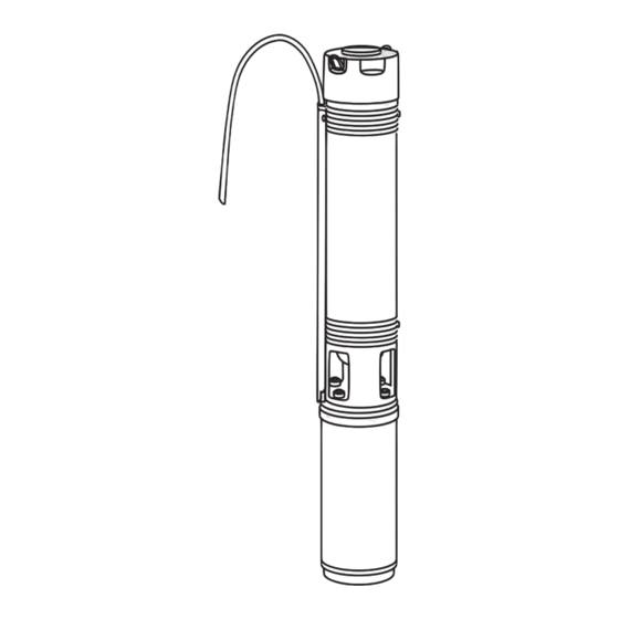
  • Page 2 Fig.1: Fig.2: Fig.3: Z UW B M 1 ~ M 1 ~ M 3 ~ Fig.4: Fig.5: Min. 0,20 0,30 - 1,00 m...
  • Page 3: Table Des Matières

    Einbau- und Betriebsanleitung Installation and operating instructions Notice de montage et de mise en service Instrucciones de instalación y funcionamiento Montaj ve kullanma k°lavuzu...
  • Page 5: Einbau- Und Betriebsanleitung

    Grenzwerte dürfen auf keinen Fall beschädigen. 'Vorsicht' bezieht sich auf mögli- unter- bzw. überschritten werden. che Produktschäden durch Missachten des Hin- weises. HINWEIS: Ein nützlicher Hinweis zur Handhabung des Produktes. Er macht auch auf mögliche Schwierigkeiten aufmerksam. Einbau- und Betriebsanleitung Wilo-Sub TWU4...
  • Page 6: Transport Und Zwischenlagerung

    Jede darüber hinausgehende Verwendung gilt als • Schaltkasten mit Motorschutz (integrierter Kon- nicht bestimmungsgemäß. densator - baugrößenabhängig) • Wilo Fluid Control (Wilo Druckschaltung) • 30 m Kabel zwischen Pumpe und Schaltkasten • 30 m Sicherungsseil HINWEIS: Die elektrischen Verbindungen erfolgen werkseitig.
  • Page 7: Beschreibung Und Funktion

    Deutsch 7.1 Installation. • Trockenlaufschutz: Schwimmerschalter oder Elektrode VORSICHT! Gefahr vor Sachschäden! • WILO-ER Schaltgerät (Motorschutz + Wasser- Gefahr der Beschädigung durch unsachgemäße standsüberwachung) Handhabung. Die Bohrlöcher oder Pumpstatio- • Motorkabel: als Bausatz (incl. Stecker) oder als nen müssen nach den allgemein gültigen techni- Meterware (ohne Stecker) schen Regel an-, ausgelegt werden.
  • Page 8 1~ 230 V, 50 Hz, EMSC-Version (Fig. 2) 5,50 13,7 Leistung Stromaufnahme Anlauf Betrieb 7,50 18,0 230 V Anschlüsse (Aderkennzeichnung) 0,37 siehe Fig. 1 - 3 0,55 0,75 schwarz 1,10 blau / grau 1,50 11,1 braun 2,20 15,9 grün / gelb WILO AG 01/2008...
  • Page 9 Temperatur von 3°C und einer max. Temperatur von 30°C betrieben wer- den. Um die Kühlung des Motors bei höheren Temperaturen zu gewährleisten, muss die Förder- leistung proportional zur Motorleistung reduziert werden (siehe nachstehende Tabelle). Einbau- und Betriebsanleitung Wilo-Sub TWU4...
  • Page 10 Zusätzlichen ergänzen. Lässt sich die Betriebsstörung nicht beheben, wenden Sie sich bitte an das Fachhandwerk oder an die nächstgelegene Wilo Kundendienststelle oder Vertretung. 11 Ersatzteile Die Ersatzteil-Bestellung erfolgt über örtliche Fachhandwerker und/oder den Wilo Kunden- dienst.
  • Page 11: Installation And Operating Instructions

    There is a risk of damaging the pump/unit. 'Cau- tion' implies that damage to the product is likely if the information is disregarded. NOTE: Useful information on using the product. It draws attention to possible problems. Installation and operating instructions Wilo-Sub TWU4...
  • Page 12: Transport And Interim Storage

    • Single-phase motor • Switchbox with motor protection (integrated condenser - depending on size) • Wilo Fluid Control (Wilo pressure circuit) • 30 m cable between pump and switchbox • 30 m securing cable NOTE: the electrical connections are made at the works.
  • Page 13: Description And Function

    English 7.1 Installation. • WILO-ER switchgear (motor protection + water level monitor) CAUTION! Risk of damage! • Motor cable:as a kit (including plug) or by the The product may be damaged if it is not handled metre (without plug) correctly.The boreholes or pump stations must •...
  • Page 14 CAUTION! Risk of damage! The motor may be damaged if it is not connected correctly. • Do not separate the cable between the switchbox and the pump. The switchbox contains the neces- sary motor condensers (EM and EMSC versions only). WILO AG 01/2008...
  • Page 15 3°C and a maximum temperature of 30°C.To guaran- tee cooling of the motor at higher temperatures, the flow rate must be reduced proportionally to the motor power (see following table). Installation and operating instructions Wilo-Sub TWU4...
  • Page 16: Spare Parts

    If the operating fault cannot be remedied, please contact the trade or your nearest Wilo customer service office or agent. 11 Spare parts Spare parts can be ordered via the local trade and/ or the Wilo customer service office.
  • Page 17: Généralités

    REMARQUE : Remarque utile sur le maniement du produit. Elle fait remarquer les difficultés éven- tuelles. Notice de montage et de mise en service Wilo-Sub TWU4...
  • Page 18: Transport Et Entreposage

    Contenance en sable 50 g/ m³ max. 4 Applications Tension réseau : Monophasé 230 V, tri- Les pompes submersibles Wilo-Sub TWU4 sont phasé 400 V destinées au pompage d'eaux claires ou peu char- Fréquence du réseau : 50 Hz gées ne présentant pas de particules fibreuses ni...
  • Page 19: Accessoires En Option

    Le clapet antiretour santé. doit résister à une pression de fonctionnement • L’installation et le raccordement électrique doi- de 20 bars minimum ! vent être effectués par un personnel spécialisé Notice de montage et de mise en service Wilo-Sub TWU4...
  • Page 20: Raccordement Électrique

    13,7 Puissance Consommation de Démarra Fonction 7,50 18,0 courant 230 V nement Raccordements (identification des fils) 0,37 Voir fig. 1 - 3 0,55 0,75 noir 1,10 bleu / gris 1,50 11,1 marron 2,20 15,9 vert / jaune WILO AG 01/2008...
  • Page 21: Mise En Service

    3°C et 30°C. En cas de températures élevées, le débit doit être réduit proportionnellement à la puissance du moteur (voir tableau ci-après) afin de garantir le refroidissement du moteur. Notice de montage et de mise en service Wilo-Sub TWU4...
  • Page 22 Si les perturbations persistent, veuillez faire appel à un technicien spécialisé, au service clientèle Wilo le plus proche ou à un représen- tant. 11 Pièces de rechange Les pièces de rechange doivent être commandées auprès d'un technicien local spécialisé...
  • Page 23 4 de este manual. puede resultar dañado si no se respetan las indi- Asimismo, los valores límite indicados en el catá- caciones. logo o ficha técnica no deberán sobrepasarse por exceso ni por defecto. Instrucciones de instalación y funcionamiento Wilo-Sub TWU4...
  • Page 24: Transporte Y Almacenamiento

    • caja de bornes con protección de motor (condensa- dor integrado, según el tamaño de la construcción) • Wilo Fluid Control (dispositivo de conmutación de presión Wilo) • 30 m de cable entre la bomba y la caja de bornes •...
  • Page 25: Accesorios (Opcional)

    • Protección contra marcha en seco: Interruptor de flotador o electrodo 7.1 Instalación. • Aparato de conmutación WILO-ER (protección de ¡ATENCIÓN! ¡Peligro de daños materiales! motor y control de estado del agua) Peligro de daños por manejo inadecuado. Las •...
  • Page 26: Conexión Eléctrica

    Potencia Toma de corriente Arranque Funciona- 7,50 18,0 230 V miento Conexiones (marcaciones de los cables) 0,37 véanse figs. 1 - 3 0,55 0,75 negro 1,10 azul / gris 1,50 11,1 marrón 2,20 15,9 verde / amarillo WILO AG 01/2008...
  • Page 27: Puesta En Marcha

    3°C y una máxima de 30°C. Para garantizar la refrigeración del motor a altas temperaturas, se deberá reducir la potencia de impulsión de forma proporcional a la potencia del motor (véase la tabla que aparece a continuación). Instrucciones de instalación y funcionamiento Wilo-Sub TWU4...
  • Page 28 El encargo de piezas de repuesto se realiza a través de un taller especializado en su lugar de residencia y/o por medio del servicio técnico de Wilo. Para evitar posteriores consultas y pedidos erró- neos, indique en cada pedido los datos completos de la placa de características.
  • Page 29: Montaj Ve Kullanma K°Lavuzu

    °lmamal°d°r veya bu de erlerin alt°na dü ülme- Pompa veya tesisatta ar°za riski. ‘Dikkat’ melidir. ikaz°n°n dikkate al°nmamas° durumunda üründe veya sistemde hasar meydana gelebilece ini belirtir. NOT: Ürünün i letiminde faydal° bilgiler. Kul- lan°c°y° olas° problemler konusunda uyar°r. Montaj ve kullanma k°lavuzu Wilo-Sub TWU4...
  • Page 30: Kullanim Amaci

    • seçene i • Motor korumal° kumanda kutusu (entegre kondanzatör - yap° ebad°na ba l°) • Wilo Fluid Control (Wilo Bas°nç Kumandas°) • Pompa ile kumanda kutusu aras°nda 30 m kablo • 30 m sigorta halat° NOT: Elektrik ba lant°lar° fabrikada yap°lmaktad°r.
  • Page 31 Türkçe pompa istasyonlar° genel geçerli teknik • WILO-ER kumanda cihaz° (motor korumas° + su seviyesi denetimi) kurallara uygun olarak aç°l°p kapat°lmal°d°r. • Motor kablosu: Montaj seti (fi dahil) veya metreli D KKAT! Maddi hasar tehlikesi! ürün (fi siz) olarak Montaj°n 4"'ten büyük bir sondaj deli ine •...
  • Page 32 D KKAT! Maddi hasar tehlikesi! Motorun ba lant°s°n°n do ru yap°lmamas° durumunda motor hasar görebilir! • Kumanda kutusu ile pompa aras°ndaki kabloyu ay°rmay°n. Kumanda kutusu motorun gerekli kondanzatörlerini içermektedir (sadece EM ya da EMSC modellerinde). • Topraklama yap°n WILO AG 01/2008...
  • Page 33 Dalg°ç motorlu pompalar en az 3°C'lik bir s°cakl°k ile en fazla 30°C'lik bir s°cakl°k aras°nda çal° t°r°labilir. Motorun so utmas°n° yüksek s°cakl°klarda sa lamak için basma gücü motor gücüyle orant°l° olarak azalt°lmal°d°r (a a °daki tabloya bak°n). Montaj ve kullanma k°lavuzu Wilo-Sub TWU4...
  • Page 34: Yedek Parçalar

    Diyaframl° genle me tank°n° daha büyük bir tank ile de i tirin veya ilave bir tank koyun. letim ar°zas° giderilemiyorsa, lütfen yetkili servise veya en yak°n Wilo mü teri hizmetine veya temsilcisine ba vurun. 11 Yedek parçalar Yedek parça sipari i yerel yetkili servisler ve/veya Wilo mü...
  • Page 35 – • • • • « » . « » Wilo-Sub TWU4...
  • Page 36 -8 °C. : 230 , : 400 IP 68 Wilo-Sub TWU4 Ø 1 " 2" 30 °C • • • • 5.3.1 • . .). • EMSC • • 1,5, 2,5 (VDE/KTW) 4 x 1,5 • • WILO AG 01/2008...
  • Page 37 5.3.2 Plug & Pump • • • Wilo Fluid Control ( Wilo); • • 30 . • • • • • • WILO-ER ( • • • . 4) Wilo-Sub TWU4" . 5) • ER ( • — • •...
  • Page 38 4 x 16 EM / EMSC 0,25 , 50 0,37 0,55 0,75 1,10 1,50 2,20 0,37 , 50 0,55 0,75 1,10 1,50 2,20 3,00 3,70 4,00 5,50 7,50 ( / ) 0,20 0,25 0,30 0,40 0,65 0,85 WILO AG 01/2008...
  • Page 39 • 7,50 18,0 • . 1 - 3 3 °C 30°C ( • 0,37 EM EMSC). 35 °C 95 % • 40 °C 95 % • 45 °C 90 % 50 °C 80 % 55 °C 70 % Wilo-Sub TWU4...
  • Page 40 • 55 °C. • • 0,20 • Wilo. Wilo. WILO AG 01/2008...
  • Page 41: Eg-Konformitätserklärung

    If the above mentioned series are technically modified without our approval, this declaration shall no longer be applicable. Si les gammes mentionnées ci-dessus sont modifiées sans notre approbation, cette déclaration perdra sa validité. Dortmund, 16.05.2008 Erwin Prieß WILO AG Quality Manager Nortkirchenstraße 100 44263 Dortmund...
  • Page 42: Rus

    EN 50081-1 EN 50082-1 AB-Makina Standartları 98/37/EG μ μ 98/37/EG Elektromanyetik Uyumluluk 2004/108/EG EN 60034-1 μ μ Alçak gerilim direktifi 2006/95/EG 2004/108/EG Kısmen kullanılan standartlar: μ EG–2006/95/EG μ μ μ μ Erwin Prieß WILO AG Quality Manager Nortkirchenstraße 100 44263 Dortmund...
  • Page 43 Lithuania Serbia and Montenegro Taiwan WILO SALMSON WILO Lietuva UAB WILO Hrvatska d.o.o. WILO Magyarország Kft WILO Beograd d.o.o. WILO-EMU Taiwan Co. Ltd. Argentina S.A. 03202 Vilnius 10090 Zagreb 2045 Törökbálint 11000 Beograd 110 Taipeh C1270ABE Ciudad T +370 5 2136495...
  • Page 44 WILO AG Nortkirchenstraße 100 44263 Dortmund Germany T 0231 4102-0 F 0231 4102-7363 wilo@wilo.de www.wilo.de Wilo-Vertriebsbüros in Deutschland G1 Nord G3 Sachsen/Thüringen G5 Südwest G7 West WILO AG WILO AG WILO AG WILO AG Vertriebsbüro Hamburg Vertriebsbüro Dresden Vertriebsbüro Stuttgart Vertriebsbüro Düsseldorf...

Table des Matières