Publicité

Les langues disponibles

Les langues disponibles

Liens rapides

I N S T A L L A T I O N I N S T R U C T I O N S
I N S T R U C T I O N S D ' I N S T A L L A T I O N
M O N T A G E A N L E I T U N G
RSE Projector Mounts
Supports pour projecteur RSE
RSE-Projektorhalterungen
RSE

Publicité

Table des Matières
loading

Sommaire des Matières pour CHIEF RSE

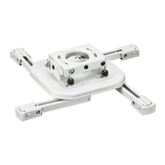
  • Page 1 I N S T R U C T I O N S D ' I N S T A L L A T I O N M O N T A G E A N L E I T U N G RSE Projector Mounts Supports pour projecteur RSE RSE-Projektorhalterungen...
  • Page 2: Installation Instructions

    RSE does not exceed 25 lbs product. The information contained in this document is subject (11.37 kg).
  • Page 3 Installation Instructions LEGEND Pencil Mark Tighten Fastener Marquage au crayon Serrez les fixations Segno a matita Serrare il fissaggio Stiftmarkierung Befestigungsteil festziehen Marcar con lápiz Apretar elemento de fijación Potloodmerkteken Bevestiging vastdraaien Marcar com lápis Apertar fixador Drill Hole Loosen Fastener Percez un trou Desserrez les fixations Praticare un foro...
  • Page 4: Tools Required For Installation

    #10-24 steel threaded rods (Qty. 4) • #10-24 channel nuts (Qty. 4) • #10-24 jam nuts (Qty. 8) • #10 washers (Qty. 8) PARTS A (1) [RSE] All-Points Security (Optional) B (1) Example Only (Interface bracket C (2) D (2)
  • Page 5 CPA adapter CPA Adapter Removal CPA adapter NOTE: If installing RSE to anything other than a CPA column, the CPA adapter portion must be removed from RSE mount prior to installation. Loosen set screw holding CPA adapter to RSE mount.
  • Page 6 IMPORTANT ! : When RSE is properly positioned, the set screw access hole should be pointing directly at target. (see bottom detail in figure at left) Secure RSE to pipe by turning set screw with a 5/32" hex key until tight. CAUTION: DO NOT OVERTIGHTEN! Overtightening of set screw can damage threads on pipe.
  • Page 7 2" x 4" wood stud cross bracing (Ø 3/32”) (1-1/2" on center) between two ceiling joists. Using the RSE as a guide, mark four mounting hole locations with a pencil or similar tool. Hole locations 45mm must be centered on 2" x 4" cross braces.
  • Page 8 MUST be capable of supporting five times the combined weight of all equipment being mounted. Ø 6.3mm Using the RSE as a guide, mark four mounting hole (Ø 1/4”) locations on ceiling using a pencil or similar tool. Drill four 1/4" (6.3mm) diameter pilot holes to a depth of 2-1/2"...
  • Page 9 Install the RSE on the threaded rod. NOTE: Hole in the RSE allows socket wrench access 45mm without unit disassembly. Secure the RSE to the threaded rod using four #10 channel nuts. (1-3/4”) PROJECTOR INSTALLATION IMPORTANT ! : Model RSE uses optional Chief "SSB"...
  • Page 10 Installation Instructions Example Only (Interface bracket varies dependent WARNING: IMPROPER INSTALLATION CAN on projector model) LEAD TO PROJECTOR FALLING RESULTING IN SERIOUS PERSONAL INJURY OR DAMAGE TO EQUIPMENT. DO NOT substitute hardware. Use only the hardware provided by the manufacturer. Secure interface bracket to mount using installation instructions and hardware provided with interface bracket.
  • Page 11 Installation Instructions Example Only Securing Projector with Interface Bracket (Interface bracket to Model RSE Mount varies dependent on projector model) WARNING: IMPROPER INSTALLATION CAN LEAD TO PROJECTOR FALLING RESULTING IN SERIOUS PERSONAL INJURY OR DAMAGE TO EQUIPMENT. Make certain mounting slots in mount base slide under thumb screws and that screws are seated in the back of slots.
  • Page 12 Tighten yaw adjustment locking screw using a 5/32" hex key. Pitch Adjustment Loosen pitch adjustment locking screw on each end of the RSE projector mount using a #2 Phillips screwdriver. Adjust projector angle to desired pitch. Example Only Tighten pitch adjustment locking screw on each end...
  • Page 13 Installation Instructions Roll Adjustment Loosen roll adjustment locking screw on each side of the RSE projector mount using a #2 Phillips screwdriver. Adjust projector to desired roll position. Example Only Tighten roll adjustment locking screw on each side (Interface bracket...
  • Page 14: Clauses De Non-Responsabilité

    Milestone ne consent aucune garantie, expresse ou implicite, au titre des • La capacité de poids du RSE peut être LIMITÉE à la informations contenues dans le présent document. Milestone capacité de poids la plus basse de tout autre élément ne garantit pas que les informations mentionnées au présent...
  • Page 15: Outils Nécessaires À L'installation

    6,4 mm (1/4") (béton) • Écrous crénelés #10-24 (Qté 4) • Contre-écrous #10-24 (Qté 8) • Rondelles #10 (Qté 8) PIÈCES A (1) [RSE] Kit de sécurité (en option) All-Point B (1) A titre d'exemple (la patte de fixation C (2)
  • Page 16: Installation Du Rse

    Assurez-vous que les trous sont alignés sur Tuyau CMA (non fourni) l'adaptateur CPA du RSE et la colonne CPA du RSE (non incluse), soulevez le RSE jusqu'à l'ouverture en bas de la colonne CPA. (Voir la Figure 1) plaque adaptatrice trou sur le côté...
  • Page 17 DOIVENT être capables de supporter cinq fois le poids total de l'équipement monté. Alignez le RSE avec l'extrémité du tuyau NPT. Vissez le RSE au tuyau en tournant dans le sens contraire des aiguilles d'une montre jusqu'à ce qu'il Alignement approximatif du RSE...
  • Page 18 Percez quatre trous de guidage de 2,5 mm (3/32") de diamètre à une profondeur de 45 mm (1-3/4"). Alignez les quatre trous de montage du RSE sur les quatre trous de guidage. IMPORTANT ! : Assurez-vous que le support est correctement orienté...
  • Page 19 Percez quatre trous de guidage de 6,3 mm (1/4") de diamètre à une profondeur de 64 mm (2-1/2"). Alignez les quatre trous de montage du RSE sur les quatre trous de guidage. IMPORTANT ! : Assurez-vous que le support est correctement orienté...
  • Page 20: Installation Du Projecteur

    RPE sur les tiges filetées. Reportez-vous à la section 1a pour plus de détails. Le RSE doit être suspendu à l'aide de quatre tiges filetées (non incluses) #10-24 de diamètre (minimum), qui sont fixées à des membres structurels en hauteur d'assemblage de canal, d'angle ou Unistrut (armatures ou poutrelles) par des contre-écrous #10-24 (non inclus).
  • Page 21 Installation Instructions A titre d'exemple (la patte de fixation d'interface AVERTISSEMENT : varie en fonction UNE MAUVAISE du modèle de projecteur) INSTALLATION PEUT PROVOQUER LA CHUTE DU PROJECTEUR ET ENDOMMAGER CELUI-CI, VOIRE ENTRAÎNER DES BLESSURES CORPORELLES GRAVES. NE PAS substituer le matériel. Utilisez uniquement le matériel fourni par le fabricant.
  • Page 22 Installation Instructions A titre d'exemple Fixation du projecteur avec la patte (la patte de fixation d'interface au support de modèle RSE d'interface varie en fonction du modèle de projecteur) AVERTISSEMENT : UNE MAUVAISE INSTALLATION PEUT PROVOQUER LA CHUTE DU PROJECTEUR ET ENDOMMAGER CELUI-CI, VOIRE ENTRAÎNER DES BLESSURES...
  • Page 23: Réglage De L'inclinaison

    5/32". Réglage de l’inclinaison Desserrez la vis de verrouillage du réglage de l'inclinaison sur chaque extrémité du support pour projecteur RSE en utilisant un tournevis Phillips #2. A titre d'exemple Réglez l'angle du projecteur pour obtenir (Patte de fixation l'inclinaison souhaitée.
  • Page 24 Installation Instructions Réglage de l’ondulation Desserrez la vis de verrouillage du réglage de l'ondulation sur chaque côté du support pour projecteur RSE en utilisant un tournevis Phillips #2. Réglez le projecteur pour obtenir l'ondulation A titre d'exemple souhaitée. (la patte de fixation d'interface Serrez la vis de verrouillage du réglage de...
  • Page 25: Wichtige Sicherheitshinweise

    Haftung für eventuelle Schadensfälle in Verbindung mit der Installation oder Verwendung dieses Produkts. Die in diesem • Die maximale Tragkraft der RSE ist auf die maximale Dokument enthaltenen Informationen können ohne vorherige Tragkraft des zwischen der RSE und der tragenden Ankündigung oder sonstige Verpflichtungen jederzeit geändert...
  • Page 26 Installation Instructions ABMESSUNGEN PUNKT ZUR EI NSTEL L UNG DES QUERNE IGUNGSWINKEL S PUNKT ZUR EI N STEL L UNG DER DREHUN G UM DIE QUERACHSE FÜR DIE MONTAGE ERFORDERLICHES WERKZEUG Erforderliche Befestigungsmaterialien – nicht mitgeliefert (abhängig von der Installationsmethode) Montage an einer Ausziehsäule mit Gewinde •...
  • Page 27 Installation Instructions A (1) [RSE] All-Points- Sicherheits- (Optional) paket B (1) Nur ein Beispiel (Anschlussplatte C (2) D (2) je nach Projektor- M16x6mm M16x6mm (Sicherheit) modell verschieden)
  • Page 28 Linse und Leinwand kennen. Die technischen Daten des Projektors bieten Ihnen Informationen zur Bestimmung dieses Abstands. Schieben Sie die RSE so in die untere Öffnung der (nicht mitgelieferten) CPA-Säule, dass die Löcher CPA-Rohr des CPA-Adapters der RSE und der CPA-Säule (nicht mitgeliefert) genau übereinander liegen.
  • Page 29 Projektorziel zeigt. WICHTIG! Wenn die RSE richtig positioniert ist, sollte das Feststellschrauben-Zugangsloch direkt auf das Ziel zeigen. (Siehe Detail in der Abb. links) Befestigen Sie die RSE am Rohr, indem Sie die Feststellschraube mit einem 5/32"-Inbusschlüssel festziehen. VORSICHT: ZIEHEN SIE DIE SCHRAUBEN NICHT ZU FEST AN! Bei Überziehen der Feststellschraube können...
  • Page 30 (38,1 mm / 1-1/2" von Mitte zu Mitte) aus 51 mm x 102 mm (2" x 4")-Holzbalken zwischen zwei Deckenbalken. Zeichnen Sie mithilfe der RSE als Schablone mit einem Bleistift oder Ähnlichem vier Bohrstellen an. Die Bohrstellen müssen jeweils in der Mitte zweier 51 mm x 102 mm (2"...
  • Page 31 Weitere Informationen dazu finden Sie in Abschnitt 1a. Wählen Sie eine Montagestelle aus. WARNUNG: Die RSE eignet sich zur Montage an eine Betondecke mit einer Mindeststärke von 203 mm (8") und einer Gipskartonbeschichtung von maximal 16 mm (5/8"). WARNUNG: EINE UNSACHGEMÄSSE MONTAGE KANN ZU SCHWEREN VERLETZUNGEN ODER GERÄTESCHÄDEN FÜHREN! Die Bauteile MÜSSEN...
  • Page 32: Montage Des Projektors

    Das Loch in der RSE ermöglicht die Verwendung eines Steckschlüssels, ohne dass das Bauteil auseinandergebaut werden muss. Befestigen Sie die RSE mit vier Nr. 10- Rechteckmuttern an den Gewindestangen. MONTAGE DES PROJEKTORS WICHTIG! Das RSE-Modell lässt sich mit den optionalen Anschlussplatten der Chief-Serie "SSB"...
  • Page 33 Installation Instructions Nur ein Beispiel (Anschlussplatte je nach Projektor- WARNUNG: EINE UNSACHGEMÄSSE MONTAGE modell verschieden) KANN ZUM HERUNTERFALLEN DES PROJEKTORS FÜHREN UND SCHWERE VERLETZUNGEN ODER GERÄTESCHÄDEN VERURSACHEN. Verwenden Sie KEINE Ersatz-Befestigungsmittel. Verwenden Sie nur die vom Hersteller mitgelieferten Befestigungsmaterialien. Befestigen Sie die Anschlussplatte mithilfe der der Anschlussplatte beiliegenden Montageanleitung und Befestigungsmaterialien an der Halterung.
  • Page 34 Installation Instructions Nur ein Beispiel Befestigen des Projektors mit der (Anschlussplatte Anschlussplatte an der RSE-Halterung je nach Projektor- modell verschieden) WARNUNG: EINE UNSACHGEMÄSSE MONTAGE KANN ZUM HERUNTERFALLEN DES PROJEKTORS FÜHREN UND SCHWERE VERLETZUNGEN ODER GERÄTESCHÄDEN VERURSACHEN. Stellen Sie sicher, dass die Montageschlitze in der Montagebasis unter die Flügelmuttern geschoben werden und dass sich die...
  • Page 35 Drehung um die Höhenachse mit einem 5/32"- Inbusschlüssel fest. Einstellung der Drehung um die Querachse Lösen Sie an den beiden Enden der RSE- Projektorhalterung jeweils die Feststellschraube für die Einstellung der Drehung um die Querachse mit einem Nr. 2-Kreuzschlitzschraubendreher.
  • Page 36 Installation Instructions Einstellung des Querneigungswinkels Lösen Sie auf der Vorder- und Rückseite der RSE-Projektorhalterung jeweils die Feststellschraube für die Einstellung des Querneigungswinkels mit einem Nr. 2-Kreuzschlitzschraubendreher. Nur ein Beispiel Bringen Sie den Projektor in die gewünschte (Anschlussplatte Querneigungsposition. je nach Projektor- modell verschieden) Ziehen Sie auf der Vorder- und Rückseite der...
  • Page 37 F 877.894.6918 / 952.894.6918 Europe A Franklinstraat 14, 6003 DK Weert, Netherlands P +31 (0) 495 580 852 Chief Manufacturing, a products division F +31 (0) 495 580 845 of Milestone AV Technologies Asia Pacific A Office No. 1 on 12/F, Shatin Galleria...
  • Page 38 Installation Instructions...

Table des Matières