Table des Matières
Publicité
Les langues disponibles
Les langues disponibles
Liens rapides
Publicité
Chapitres
Table des Matières

Manuels Connexes pour SCS Sentinel INTENSIVE 3A


Sommaire des Matières pour SCS Sentinel INTENSIVE 3A
- Page 1 Manuel d’installation et d’utilisation intensive3 KIT AUTOMATISME COULISSANT Technologie par encodage pour portail Safety Comfort Moteur Moteur Crémaillères Crémaillères 2 télécommandes 2 télécommandes Feu clignotant Feu clignotant Photocellules...
-
Page 2: Table Des Matières
TABLE DES MATIERES 1. PRÉCAUTIONS POUR L'INSTALLATEUR 2. INSTALLATION 2.1 INSTALLATION DE L’AUTOMATISME 2.2 DESCRIPTION DU DISPOSITIF 2.3 DIMENSIONS 2.4 Installation du moteur et de crémaillère 2.5 Vérification de l'installation 2.6 DÉVERROUILLAGE 3. INSTALLATION ET RÉGLAGES 3.1 Raccordement électrique 3.2 Mémorisation de l'émetteur 3.3 Système d'apprentissage et l'affichage de LED 3.4 Réglages des fonctions programmables 3.5 Essais et vérifications... -
Page 3: Précautions Pour L'installateur
1.1 PRÉCAUTIONS POUR L'INSTALLATEUR ATTENTION ! Ce manuel est uniquement destiné aux techniciens qualifiés, spécialisés dans les installa- tions d’automatismes de portail. (1) Toutes les installations, les branchements électriques, les ajustements et les tests ne doivent être effectués qu'après une lecture attentive et une bonne compréhension des instructions. (2) Avant de commencer toute opération d'installation ou d'entretien, débranchez l'alimentation électrique. -
Page 4: Installation
2. INSTALLATION 2.1 INSTALLATION DE L’AUTOMATISME 1. 24Vdc automatisme coulissant 2. Télécommande 3. Photocellule 4. Feu clignotant avec antenne intégrée 2.2 DESCRIPTION DU DISPOSITIF a. Motoréducteur e. Déverrouillage b. Fin de course f. Panneau de commande c. 24Vdc moteur g. Terminals d. -
Page 5: Dimensions
2.3 DIMENSION 2.4 INSTALLATION DU MOTEUR ET DE CRÉMAILLÈRE Percez Maintenez le niveau Pignon moteur Tracez... -
Page 6: Vérification De L'installation
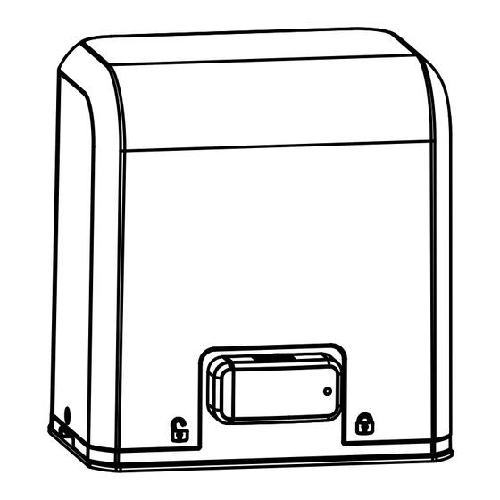
2.5 VÉRIFICATION DE L'INSTALLATION 2.6 DÉVERROUILLAGE En cas de besoin, la porte peut s’actionner manuellement Etape 1. Poussez le couvercle de déverrouillage et déplacez-le vers la droite. Etape 2. Insérez la clé et tournez dans le sens horaire pour déverrouiller l'appareil. Etape 3. -
Page 7: Installation Et Réglages
3. INSTALLATION ET RÉGLAGES 3.1. RACCORDEMENT ÉLECTRIQUE Si le signal LED fonctionnant normalement, se réfère à "4.2.1", vous pouvez contrôler la portail par les émetteurs ou presser le bouton. Sur le plateau: “UP” - mouvement dans le sens des aiguilles d’une montre “SET”... -
Page 8: Reconnaissance De La Télécommande
3.2 RECONNAISSANCE DE LA TÉLÉCOMMANDE Appuyez sur le bouton de "RF Learn” pendant 3 secondes (allume le LED 3) puis appuyez sur le bouton de l'émetteur (A), (la LED3 clignote deux fois, puis s'éteint). A ce stade, l'apprentissage de l'émetteur est terminé. LED1 LED2 LED3... -
Page 9: Réglages Des Fonctions Programmables
3.4 RÉGLAGES DES FONCTIONS PROGRAMMABLES Maintenez la touche SET pendant 3 secondes. F1 apparaît. Vous êtes dans le mode réglage. Faites défiler les programmes en appuyant sur la touche UP. Quand le programme désiré apparaît, appuyez sur la touche SET pour rentrer dans le programme. Definition Fonction Affichage... -
Page 10: Essais Et Vérifications
● F3 réglages des fonctions : Logic F3-1 Réactions des photocellules lors de la détection d’obstacle L'état du portail Photocellule 2 Photocellule 1 Photocellule 1/ Photocellule 2 Fermée Arrêter l'ouverture Aucun effet Arrêter l'ouverture Ouverte Aucun effet Recharge le temps de fermeture automatique Arrête pendant Arrêter l'ouverture Recharge le temps de fermeture automatique... -
Page 11: Réglages Sw2 Et Sw6
3.6 RÉGLAGES SW2/SW6 Par défaut Switch Touche Description SWITCH TOUCHE A OUVERTURE TOTALE 4 et 5 TOUCHE B PASSAGE PIÉTON sur ON TOUCHE C DÉCLENCHEMENT CONTACT SEC EXT+ ET EXT- BORNE 1 ET 2 TOUCHE D DÉCLENCHEMENT CONTACT SEC EXT+ ET EXT- BORNE 1 ET 2 SWITCH TOUCHE A OUVERTURE TOTALE... -
Page 12: Caractéristiques Techniques
4. CARACTÉRISTIQUES TECHNIQUES: 4.1 CARACTERISTIQUES TECHNIQUES DU BOXER: Moteur INTENSIVE 3A INTENSIVE 3B Type d'engin Motoréducteur Motoréducteur Force de poussée 3300N 5500N Force de poussée nominal 3500N 5000N RPM d’engin 3800 RPM 3800 RPM Puissance (W) Motor éléctrique 24 Vdc... - Page 13 Installation and user manual intensive3 AUTOMATION KIT SLIDING Encoding system for gate Safety Comfort Motors Motors Rack Rack 2 remote control 2 remote control Blinker Blinker Photocells...
- Page 14 INDEX 1. GENER SAFETY PRECUATION 2. INSTALLATION 2.1 STANDARD INSTALLATION 2.2 DESCRIPTION OF DEVICE 2.3 DIMENSION OF DEVICE 2.4 INSTALLATION OF GEAR MOTOR AND GEAR RACK 2.5 CHECKING FOR INSTALLATION 2.6 EMERGENCY RELEASE 3. SETUP AND FUNCTION SETTING 3.1 WIRE CONNECTION 3.2 TRANSMITTER MEMORIZATION 3.3 SYSTEM LEARNING AND LED DISPLAY 3.4 PROGRAMMABLE FUNCTION SETTINGS...
- Page 15 1. GENERAL PRECAUTION WARNING : This user manual is only for qualified technicians who is specialized in installations and automations. (1) All installations, electrical connections, adjustments and testing must be performed only after reading and understanding of all instructions carefully. (2) Before carrying out any installation or maintenance operation, disconnect the electrical power supply by turning off the magneto thermic switch connected upstream and apply the hazard area notice required by applicable regulations...
-
Page 16: Installation
2. INSTALLATION 2.1 STANDARD INSTALLATION 1. 24Vdc Sliding motor 2. Transmitter 3. safety photo Sensor 4. Flashing light 2.2 DESCRIPTION OF DEVICE a. Operation gear e. Release device b. Limit switch device f. Control panel c. 24Vdc motor g. Terminals of devices d. -
Page 17: Dimension Of Device
2.3 DIMENSION OF DEVICE 2.4 INSTALLATION OF MOTOR GEAR AND GEAR RACK Drill keep the level Motor pinion Trace... -
Page 18: Checking For Installation
2.5 CHECKING FOR INSTALLATION 2.6 EMERGENCY RELEASE In the case of power failure for emergency release of the motor, please follow the procedure as below: Step1. Push the lid of release chamber and move rightward Step2. Insert the key and turn clockwise to unlock the device Step3. -
Page 19: Setup And Function Setting
3. SETUP AND FUNCTION SETTING 3.1. WIRE CONNECTION If the Led display is in normal performing refer to “4.2.1”, you can control the gate by either transmitters or the button on the board: “UP”-clockwise moving, “SET”- stop and “DOWN”- Counterclockwise moving. PB1, KS1=: LED1 Photocells LED2 Photocells... -
Page 20: System Learning And Led Display
3.2 Transmitter memorizing Press “RF Learn” button for 3 seconds, and the LED3 is on; then press the transmitter button (A); the LED3 will blink twice and then be off. The transmitter learning is completed. LED1 LED2 LED3 LED 3 3 Sec LED 3 LED 3 OFF... -
Page 21: Programmable Function Settings
3.4 PROGRAMMABLE FUNCTION SETTINGS LED Display Definition Function Value Description 1. The function can adjust the dir Options of Gate F1-0 Clockwise Opening ection of gate opening. Opening direction F1-1 Counterclockwise Opening 2. The factory setting is "F1-1". Automatic Closing F2-0 No automatic closing F2-1... -
Page 22: Testing And Checking
● F3 function settings: Logic F3-1 The reactions of the photocells when detecting obstacles Gate Status Photocell 2 Photocell 1 Photocell 1/ Photocell 2 Closed Stop opening No effect Stop opening Open No effect Reloads automatic closing time Stop during moving Stop opening Reloads automatic closing time Closing... -
Page 23: Sw2/Sw6 Settings
SW2/SW6 SETTING Default DeviceSWITCH Button Description SWITCH BUTTON A TOTAL OPENING 4 and 5 BUTTON B PEDESTRIAN ACCESS on ON BUTTON C RELEASE RELAY EXT+ AND EXT- DEVICE 1 ET 2 BUTTON D RELEASE RELAY EXT+ AND EXT- DEVICE 1 ET 2 SWITCH BUTTON A TOTAL OPENING... -
Page 24: Technical Characteriestics
4. TECHNICAL CHARACTERISTICS 4.1 TECHNICAL DATA SHEET OF BOXER SERIES Motor INTENSIVE 3A INTENSIVE 3B Gear type Worm Gear Worm Gear Peak thrust 3300N 5500N Nominal thrust 3500N 5000N Engine RPM 3800 RPM 3800 RPM Absorbed Power Power supply 24 Vdc... -
Page 25: Bon De Commande
BON dE COmmANdE À reToUrner PAr coUrrIer À : Système de Communication et de Sécurité SA service commande - Rte de St Symphorien - BP 69 - 85130 Les Landes génusson (FRANCE) mes coordonnées Entreprise : ..................SIRET : ..........Nom : ............ -
Page 27: Déclaration De Garantie
déCLARATION dE gARANTIE À renVoYer : auprès de votre installateur ou distributeur gARANTIE 3 Ans VoTre ProdUIT nom : kit automatisme pour portail coulissant : InTensIVe3A InTensIVe3B code barre (numéro à 13 chiffres) : ....................N° lot (indiqué dans la zone du code barre du packaging) : ............. LIeU d’AcHAT enseigne ................ -
Page 28: Warranty Declaration
wARRANTy dECLARATION To reTUrn BY mAIL To : your installer or distributor wARRANTy 3 YeArs YoUr ProdUcT InTensIVe3A InTensIVe3B product name : automation kit for sliding gates : gencod (13 numbers) : ........................batch number (close to gencod location) : .................. PUrcHAse LocATIon company : .............. - Page 29 pour tout problème technique, veuillez contacter votre installateur ou distributeur.