
Manuels Connexes pour Yamaha F9.9C


Sommaire des Matières pour Yamaha F9.9C
- Page 1 F9.9C FT9.9D F15A OWNER’S MANUAL MANUEL D’UTILISATION MANUAL DEL PROPIETARIO 66M-28199-74...
- Page 3 EMU01419* TO THE OWNER Thank you for choosing a Yamaha out- board motor. This Owner’s manual con- A CAUTION indicates special precautions tains information needed for proper oper- that must be taken to avoid damage to ation, maintenance and care. A thorough the outboard motor.
- Page 4 FMU01419* AVIS AU PROPRIETAIRE Nous vous remercions d’avoir choisi un moteur hors-bord Yamaha. Le présent Manuel de l’Uti- ATTENTION indique les consignes qui doi- lisateur comporte les informations requises vent être respectées afin d’éviter d’endom- pour une utilisation, un entretien et des manipu- mager le moteur hors-bord.
- Page 5 Una correcta comprensión de estas sencillas instrucciones le ayudará a disfrutar plenamente NOTA: de su nuevo motor fuera borda Yamaha. Una NOTA contiene información clave que faci- Si tiene cualquier pregunta sobre el funciona- lita o aclara un procedimiento.
-
Page 6: Basic Components
EMU00003 CONTENTS GENERAL INFORMATION BASIC COMPONENTS OPERATION MAINTENANCE TROUBLE RECOVERY INDEX READ THIS OWNER’S MANUAL CAREFULLY BEFORE OPERATING YOUR OUTBOARD MOTOR. -
Page 7: Table Des Matières
FMU00003 SMU00003 CONTENIDO TABLE DES MATIERES INFORMATIONS INFORMACION GENERAL GENERALES COMPOSANTS DE BASE COMPONENTES BÁSICOS OPERATION FUNCIONAMIENTO ENTRETIEN MANTENIMIENTO RESTABLECIMIENTO EN DEPANNAGE CASO DE PROBLEMA INDEX INDICE LISEZ ATTENTIVEMENT CE LEA CUIDADOSAMENTE ESTE MANUEL DU PROPRIETAIRE MANUAL DEL PROPIETARIO ANTES AVANT D’UTILISER VOTRE DE UTILIZAR EL MOTOR FUERA MOTEUR HORS-BORD. -
Page 8: General Information
EMU00004 Chapter 1 GENERAL INFORMATION IDENTIFICATION NUMBERS RECORD ..1-1 Outboard motor serial number ...1-1 Key number ...........1-1 EMISSION CONTROL INFORMATION...1-2 SAFETY INFORMATION......1-3 FUELING INSTRUCTION ......1-5 Gasoline (petrol)........1-6 ENGINE OIL ..........1-6 BATTERY REQUIREMENT.......1-7 PROPELLER SELECTION ......1-8 START-IN-GEAR PROTECTION ....1-9... -
Page 9: Informations Generales
FMU00004 SMU00004 Chapitre 1 Capítulo 1 INFORMATIONS INFORMACION GENERALES GENERAL NUMÉROS D’IDENTIFICATION...1-1 REGISTRO DE NÚMEROS DE Numéro de série du moteur hors-bord ..1-1 IDENTIFICACIÓN ..........1-1 Numéro de clé ...........1-1 Número de serie del motor fuera borda ..1-1 INFORMATION SUR LE CONTROLE Número de llave ..........1-1 D’EMISSIONS ...........1-2 INFORMACIÓN SOBRE CONTROL DE... -
Page 10: Identification Numbers Record
Record your outboard motor serial num- ber in the spaces provided to assist you in 401012 ordering spare parts from your Yamaha dealer or for reference in case your out- board motor is stolen. 1 Outboard motor serial number... -
Page 11: Numeros D'identification
Yamaha, o bien como referencia votre distributeur Yamaha ou à titre de référen- en caso de sustracción del motor fuera borda. ce en cas de vol. -
Page 12: Emission Control Information
INFORMATION Emission control model This engine conforms to the emission con- trol regulations for Bodensee (Navigation Ordinance of Bodensee). 109*** Approval label of emission control certificate YAMAHA MOTOR CO., LTD. YAMAHA MOTOR CO., LTD. Motorfamilie F9.9 Motorfamilie Abgastypenpruf- Abgastypenpruf- M145429704... -
Page 13: Information Sur Le Controle D'emissions
Bodensee). lac de Constance). Etiqueta de aprobación del certificado de Etiquette d’agrégation du certificat de control de emisiones. contrôle des émissions YAMAHA MOTOR CO., LTD. YAMAHA MOTOR CO., LTD. YAMAHA MOTOR CO., LTD. YAMAHA MOTOR CO., LTD. Motorfamilie F9.9... -
Page 14: Safety Information
EMU00918 SAFETY INFORMATION 8 Before mounting or operating the out- board motor, read this entire manual. Reading it should give you an under- standing of the motor and its operation. 8 Before operating the boat, read any owner’s or operator’s manuals supplied with it and all labels. -
Page 15: Información Sobre Seguridad
FMU00918 SSMU00918 INFORMATIONS DE INFORMACIÓN SOBRE SECURITE SEGURIDAD 8 Antes de montar o utilizar el motor fuera Avant de monter ou de faire fonctionner le moteur hors-bord, lisez attentivement le pré- borda, lea este manual para obtener una sent manuel. Il est en effet destiné à vous faire correcta comprensión del motor y su funcio- clairement comprendre le fonctionnement du namiento. - Page 16 8 This product emits exhaust gases which contain carbon monoxide, a colorless, odorless gas which may cause brain damage or death when inhaled. Symp- toms include nausea, dizziness, and drowsiness. Keep cockpit and cabin areas well ventilated. Avoid blocking exhaust outlets. 8 Check throttle, shift, and steering for proper operation before starting the engine.
- Page 17 8 Este producto emite gases de escape que Ce produit émet des gaz d’échappement contenant du monoxyde de carbone, un gaz contienen monóxido de carbono, un gas inco- incolore et inodore capable de provoquer des loro e inodoro cuya inhalación puede provo- lésions cérébrales, voire la mort, en cas car lesiones cerebrales o incluso la muerte.
-
Page 18: Fueling Instruction
EMU00016 FUELING INSTRUCTIONS GASOLINE AND ITS VAPORS ARE HIGH- LY FLAMMABLE AND EXPLOSIVE! 8 Do not smoke when refueling, and keep away from sparks, flames, or other sources of ignition. 8 Stop engine before refueling. 8 Refuel in a well-ventilated area. Refuel portable fuel tanks off the boat. -
Page 19: Instructions Pour Le Carburant
FMU00016 SMU00016 INSTRUCTIONS POUR LE INSTRUCCIONES DE REPOSTAJE CARBURANT DE COMBUSTIBLE L’ESSENCE ET LES VAPEURS D’ESSEN- LA GASOLINA Y SUS GASES SON SUMAMEN- SONT HAUTEMENT INFLAM- TE INFLAMABLES Y EXPLOSIVOS. 8 Absténgase de fumar durante el repostaje y MABLES ET EXPLOSIVES! Ne fumez pas lorsque vous faites le plein de manténgase alejado de chispas, llamas u carburant et veillez à... -
Page 20: Gasoline(Petrol)
EMU00835 GASOLINE(PETROL) Standard Model Recommended gasoline(petrol): Regular unleaded gasoline(petrol) Unleaded fuel will give you longer spark plug life and reduced maintenance cost. If unleaded gasoline is not available, then leaded regular gasoline can be used. If leaded gasoline is usually used, engine valves and related parts should be inspect- ed after every 300 hours of operation. -
Page 21: Huile Moteur
FMU00835 SMU00835 ESSENCE GASOLINA Modèle standard Modelo estándar Essence préconisée : Gasolina recomendada Essence normale sans plomb Gasolina normal sin plomo De l’essence sans plomb allonge la durée de vie La gasolina sin plomo prolonga la vida útil de utile des bougies et réduit les frais d’entretien. las bujías y reduce los costes de mantenimien- Si de l’essence sans plomb n’est pas disponible, to. -
Page 22: Battery Requirement
Engine oil quantity: Refer to “SPECIFICATIONS”, Page 4-1. All four-stroke engines are shipped from the factory without engine oil. NOTE: 000808 If the recommended engine oil is not avail- able, then a multigrade type engine oil such as SF-CC/CD,SG-CC/CD or SH-CD can be used. -
Page 23: Requisitos De Batería
Quantité d’huile moteur: Cantidad de aceite de motor: Consulte el apartado “ESPECIFICACIONES”, Voir “SPECIFICATIONS”, page 4-1. Página 4-1. Tous les moteurs à 4 temps sont expédiés départ usine sans huile moteur. Todos los motores de cuatro tiempos se sumi- nistran de fábrica sin aceite de motor. N.B.: NOTA: Si l’huile moteur préconisée n’est pas dispo-... -
Page 24: Propeller Selection
Conversely, a larger-pitch propeller is more suitable for a smaller operating load. Yamaha dealers stock a range of pro- pellers, and can advise you and install a propeller on your outboard that is best... -
Page 25: Selección De La Hélice
Les moteurs hors-bord Yamaha sont équipés d’hélices sélectionnées en vue de fournir de Los motores fuera borda Yamaha están equipa- bonnes performances dans toute une série dos con hélices seleccionadas para rendir d’applications, mais il peut y avoir des correctamente en una serie de aplicaciones, domaines d’utilisation où... -
Page 26: Start-In-Gear Protection
PELLER” for instructions on propeller 602031 removal and installation. EMU01208 START-IN-GEAR PROTECTION Yamaha outboard motors which have the pictured label 1 affixed to them or Yama- ha approved remote control units are equipped with start-in-gear protection device(s). This feature permits the engine to be started only when it is Neutral. -
Page 27: Dispositif De Protection Contre Le Demarrage En Prise
PRISE PUESTA Les moteurs hors-bord Yamaha identifiés par Los motores fuera borda Yamaha a los que está l’étiquette 1 et les unités de commande à dis- fijada la etiqueta 1 mostrada, o las unidades de tance agréés par Yamaha sont équipés d’un (de) control remoto aprobadas por Yamaha, están... - Page 28 EMU00037 Chapter 2 BASIC COMPONENTS MAIN COMPONENTS......2-1 OPERATIONS OF CONTROLS AND OTHER FUNCTIONS ........2-3 Fuel tank..........2-3 Gear shift lever ........2-4 Choke knob ..........2-4 Recoil starter handle ......2-4 Starter button ........2-5 Tiller handle...........2-5 Remote control........2-8 Steering friction adjusting screw ..2-12 Steering friction adjusting lever..2-12 Trim angle adjusting rod....2-13 Warning indicator(s) ......2-13 Tilt lock mechanism......2-13...
-
Page 29: Composants De Base
FMU00037 SMU00037 Chapitre 2 Capítulo 2 COMPOSANTS DE COMPONENTES BASE BÁSICOS COMPOSANTS PRINCIPAUX ....2-1 PRINCIPALES.............2-1 FONCTIONNEMENT DES COMMANDES FUNCIONAMIENTO DE LOS MANDOS Y ET DES AUTRES FONCTIONS....2-3 OTRAS FUNCIONES .........2-3 Réservoir à carburant ........2-3 Depósito de combustible ......2-3 Levier de commande d’inversion ....2-4 Palanca de cambio de marcha .....2-4 Bouton de choke........2-4 Mando del estrangulador ......2-4... -
Page 30: Main Components
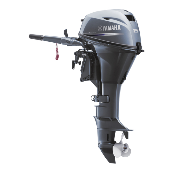
EMU01206 MAIN COMPONENTS F9.9/F15 101123* 000614 701061 101121* 902056 1 Top cowling w Warning indicator 2 Top cowling lock lever * e Gear shift lever 3 Oil drain bolt * r Tiller handle 4 Anti-cavitation plate t Clamp screw 5 Propeller y Rope attachment 6 Cooling water inlet u Tilt lock lever... -
Page 31: Composants Principaux
FMU01206 SMU01206 COMPOSANTS PRINCIPAUX PRINCIPALES COMPONENTES Capot supérieur 1 Cubierta superior 2 Palanca de bloqueo de la cubierta Levier de verrouillage du capot 3 Perno de drenaje de aceite Boulon de vidange d’huile 4 Placa anticavitación Plaque anticavitation 5 Hélice Hélice Prise d’eau de refroidissement 6 Entrado de agua de refrigeración... - Page 32 EMU01206 MAIN COMPONENTS FT9.9 000616 701061 902056 1 Top cowling * w Reoil starter handle 2 Top cowling lock lever e Warning indicator 3 Oil drain bolt * r Starter button 4 Anti-cavitation plate t Clamp screw 5 Propeller y Rope attachment 6 Cooling water inlet u Tilt lock lever 7 Trim angle adjusting rod...
- Page 33 FMU01206 SMU01206 COMPOSANTS PRINCIPAUX PRINCIPALES COMPONENTES Capot supérieur 1 Cubierta superior 2 Palanca de bloqueo de la cubierta Levier de verrouillage du capot 3 Perno de drenaje de aceite Boulon de vidange d’huile 4 Placa anticavitación Plaque anticavitation 5 Hélice Hélice Prise d’eau de refroidissement 6 Entrado de agua de refrigeración...
-
Page 34: Operations Of Controls And Other Functions
EMU00039 OPERATIONS OF CONTROLS OTHER FUNCTIONS EMU00041 FUEL TANK If your model was equipped with a 000932 portable fuel tank, its function is as fol- lows. 1 Fuel hose joint 2 Fuel meter(If equipped) 3 Fuel tank cap 4 Air vent screw(If equipped) The fuel tank supplied with this engine is its dedicated fuel reservoir and must not 902065... -
Page 35: Fonctionnement Des Commandes Et Des Autres Fonctions
FMU00039 SMU00039 FONCTIONNEMENT DES FUNCIONAMIENTO DE LOS COMMANDES ET DES MANDOS Y OTRAS FUNCIONES AUTRES FONCTIONS SMU00041 DEPOSITO DE COMBUSTIBLE FMU00041 Si su modelo está provisto de un depósito de RESERVOIR A CARBURANT combustible portátil, funcionará de la siguiente Si votre modèle a été équipé d’un réservoir à manera. -
Page 36: Gear Shift Lever
EMU00051 F9.9/F15 GEAR SHIFT LEVER (for Tiller control model) Turning the gear-shift lever towards you engages the clutch with the forward gear so that the boat moves ahead. Turning the lever away from you engages the reverse gear so that the boat moves astern. -
Page 37: Levier De Commande D'inversion
FMU00051 SMU00051 LEVIER DE COMMANDE PALANCA DE CAMBIO DE MARCHA D’INVERSION (modelo provisto de control de la caña (pour modèle à commande par barre del timón) Si gira hacia usted la palanca de cambio de franche) marcha, se engranará el embrague con la mar- Tirer l’inverseur vers soi pour enclencher la cha de avance, provocando que la embarca- marche avant (le bateau se déplace vers... -
Page 38: Starter Button
EMU00060 STARTER BUTTON (for Tiller control model) When you push the starter button, the electric starter motor cranks the engine to start it. 225011 EMU00943 F9.9/F15 TILLER HANDLE (for Tiller control model) Moving the tiller handle sideways to adjust the steering direction. In addition, this handle contains the functions as fol- lows. -
Page 39: Contacteur De Demarrage
FMU00060 SMU00060 CONTACTEUR DE DEMARRAGE BOTÓN DE ARRANQUE (pour modèle à commande par barre (modelo provisto de control de la caña franche) del timón) Une pression sur le bouton du contacteur de Cuando se pulsa el botón de arranque, se démarrage suffit pour que le moteur du démar- acciona el motor de arranque eléctrico para reur électrique lance le moteur. - Page 40 EMU00067 Throttle Indicator The fuel consumption curve on the throt- tle indicator shows the relative amount of fuel consumed for each throttle position. Choose the setting that offers the best performance and fuel economy for the desired operation. 508013 1 Throttle indicator EMU01294 Throttle Friction Adjusting Knob A friction device in the tiller handle pro-...
- Page 41 FMU00067 SMU00067 Indicateur d’accélérateur Indicador de aceleración La courbe de consommation de carburant sur La curva de consumo de combustible que apa- l’indicateur de l’accélérateur donne la consom- rece en el indicador de aceleración muestra la mation relative suivant la position de l’accélé- cantidad relativa de combustible consumida en rateur.
- Page 42 EMU00932 Engine Stop Lanyard Switch The lock-plate 1 must be attached to the engine stop lanyard switch for the engine to run. The lanyard 2 should be attached to a secure place on the operator’s cloth- ing, or arm or leg. Should the operator fall overboard or leave the helm, the lanyard will pull out the lock plate, stopping igni- 506022...
- Page 43 FMU00932 SMU00932 Cordon/coupe-contact de sécurité Interruptor del acollador de parada del motor La plaquette de coupe-contact 1 doit être Para que funcione el motor, la placa de blo- fixée au coupe-circuit de sécurité à cordon queo 1 debe estar fijada al acollador del inte- rruptor de parada del motor.
-
Page 44: Remote Control
EMU00094 REMOTE CONTROL Both the shifter and the throttle are actu- ated by the remote control lever. In addi- tion, this remote control also has the elec- trical switches. 1 Remote control lever 2 Neutral interlock trigger 3 Neutral throttle lever 000608 4 Main switch/Choke switch 5 Engine stop lanyard switch... -
Page 45: Commande À Distance
FMU00094 SMU00094 COMMANDE À DISTANCE CONTROL REMOTO L’inverseur et le papillon des gaz sont tous Tanto el cambio de marcha como el acelerador deux actionnés par le levier de la commande à se accionan mediante la palanca de control distance. Cette commande comporte en outre remoto. - Page 46 EMU00100 Neutral Throttle Lever To open the throttle without shifting into either Forward or Reverse, place the remote control lever in the Neutral posi- tion and lift the neutral throttle lever. NOTE: The neutral throttle lever will operate only when the remote control lever is in Neu- 701033* tral.
- Page 47 FMU00100 SMU00100 Levier de commande du papillon des gaz au Palanca de aceleración en punto muerto point mort Para abrir el acelerador sin cambiar a marcha Pour ouvrir le papillon des gaz sans enclencher de avance o marcha atrás, sitúe la palanca de le pignon de marche avant ou arrière, placez le control remoto en la posición de punto muerto levier de commande à...
- Page 48 EMU00934 Engine Stop Lanyard Switch The lock-plate 1 must be attached to the engine stop lanyard switch for the engine to run. The lanyard 2 should be attached to a secure place on the operator’s cloth- ing, or arm or leg. Should the operator fall overboard or leave the helm, the lanyard will pull out the lock plate, stopping igni- 701025*...
- Page 49 FMU00934 SMU00934 Cordon/coupe-contact de sécurité Interruptor del acollador de parada del motor Le coupe-contact de sécurité 1 à l’extrémité Para que funcione el motor, la placa de blo- du cordon doit être fixé au coupe-circuit du queo 1 situada en el extremo del acollador se moteur pour que celui-ci fonctionne.
- Page 50 EMU01316 Power Tilt Switch The power tilt adjusts the motor angle in relation to the transom. The power tilt switch is located on the remote control lever grip. Pushing the switch “UP” tilts the motor up. Pressing the switch “DN” tilts the motor down.
- Page 51 FMU01316 SMU01316 Contacteur de relevage assisté Interruptor de inclinación asistida Le dispositif de relevage assisté règle l’angle El mecanismo de inclinación asistida ajusta el formé par le moteur avec la barre d’arcasse. Le ángulo del motor en relación con el peto de contacteur de relevage assisté...
-
Page 52: Steering Friction Adjusting Screw
EMU00108 STEERING FRICTION ADJUSTING SCREW(for Tiller control model) A friction device provides resistance to steering movement. This is adjustable for operator preference. adjusting screw/bolt is located on the swivel brack- EMU01296 408032 Adjustment Resistance Screw/Bolt Increase Turn clockwise Decreased Turn counterclockwise over tighten friction... -
Page 53: Vis De Reglage De La Friction De La Direction
FMU00108 SMU00108 VIS DE REGLAGE DE LA FRICTION TORNILLO DE AJUSTE DE LA FRICCIÓN DE LA DIRECTION DE LA DIRECCIÓN (modelo provisto de (pour modèle à commande par barre control de caña del timón) Un dispositivo de fricción ofrece resistencia al franche) movimiento de la dirección. -
Page 54: Trim Angle Adjusting Rod
EMU01297 TRIM ANGLE ADJUSTING ROD The position of the trim angle adjusting rod determines the minimum trim angle of the outboard motor in relation to the transom. 404014 EMU01128 WARNING INDICATOR(S) If the engine develops a condition moni- tored by the warning system, an indicator will come on. -
Page 55: Tige De Reglage De L'angle D'assiette
FMU01297 SMU01297 TIGE DE REGLAGE DE L’ANGLE VARILLA DE AJUSTE DEL ÁNGULO DE D’ASSIETTE TRIMADO La position de la tige de réglage de l’angle La posición de la varilla de ajuste del ángulo de d’assiette du moteur hors-bord détermine trimado determina el ángulo de trimado míni- l’angle d’assiette minimum par rapport à... -
Page 56: Tilt Support Bar
EMU00156 TILT SUPPORT BAR The tilt support bar 1 keeps the outboard motor in the tilted up position. 403**2 EMU01348 POWER TILT UNIT This unit tilts the motor up and down and is controlled via the power tilt switch. 1 Power tilt unit 2 Power tilt motor Do not step on or exert pressure on the 000615... -
Page 57: Levier De Verrouillage Du Capot
FMU00156 SMU00156 TIGE DE SUPPORT DE RELEVAGE BARRA DE SOPORTE DE LA La tige de support de relevage 1 maintient le INCLINACION moteur hors-bord en position relevée. La barra de soporte de la inclinación 1 mantie- ne el motor fuera borda en la posición inclina- da hacia arriba. -
Page 58: Warning System
EMU00169 WARNING SYSTEM Do not continue to operate the engine if the warning device has activated. Consult your Yamaha dealer if the problem can- not be located and corrected. 701054 EMU00170 OVERHEAT WARNING This engine has an overheat warning device. If the engine temperature rises too high, the warning device will activate. -
Page 59: Systeme D'avertissement
Cessez de solliciter le moteur lorsque le dis- corregir el problema, póngase en contacto con positif d’avertissement est activé. Prenez su concesionario Yamaha. contact avec votre distributeur Yamaha si vous ne parvenez pas localiser et à résoudre le problème. FMU00170 SMU00170 SYSTEME D’AVERTISSEMENT DE... -
Page 60: Low Oil Pressure Warning
Check oil level and add oil as needed. 701054 If the oil level is correct, consult your Yamaha dealer. Do not continue to run the engine if the low oil pressure lamp is “ON”. Serious engine damage may occur. -
Page 61: Avertissement De Pression D'huile Insuffisante
Compruebe el nivel de presión del aceite y, si es necesario, añada aceite. Si el nivel de aceite es correcto, póngase en contac- to con su concesionario Yamaha. Ne continuez pas à faire fonctionner le moteur lorsque le témoin d’avertissement de pression d’huile est activé... -
Page 62: Operation
EMU00174 Chapter 3 OPERATION INSTALLATION ........3-1 Mounting the outboard motor ....3-2 Clamping the outboard motor.....3-4 BREAKING IN (RUNNING IN) ENGINE ..3-5 PRE-OPERATION CHECKS ......3-6 Checking the engine oil level....3-7 FILLING FUEL ...........3-8 STARTING ENGINE .........3-9 WARMING UP ENGINE ......3-16 SHIFTING ..........3-17 Forward..........3-17 Reverse ..........3-18 STOPPING ENGINE .......3-19... - Page 63 FMU00174 SMU00174 Chapitre Capítulo 3 OPERATION FUNCIONAMIENTO MONTAGE..........3-1 INSTALACION ...........3-1 Montage du moteur hors-bord ....3-2 Montaje del motor fuera borda....3-2 Fixation du moteur hors-bord....3-4 Fijación del motor fuera borda.....3-4 RODAGE DU MOTEUR ......3-5 RODAJE DEL MOTOR........3-5 PROCEDURE PREALABLE....3-6 PROCEDIMIENTO PREVIO A LA PUESTA EN Vérification du niveau d’huile moteur..3-7 MARCHA ............3-6 PROCEDURE DE PLEIN DE...
-
Page 64: Installation
EMU00175 INSTALLATION Incorrect engine height or obstructions to smooth water flow (such as the design or condition of the boat or accessories such as transom ladders/depth finder trans- ducers) can create airborne water spray while the boat is cruising. Severe engine damage may result if the motor is operat- ed continuously in the presence of air- borne water spray. -
Page 65: Montage
FMU00175 SMU00175 MONTAGE INSTALACION Une hauteur incorrecte du moteur ou toute Una altura incorrecta del motor u obstruccio- entrave à un écoulement fluide de l’eau nes que impidan la suavidad de marcha de la (comme la conception ou l’état du bateau ou embarcación (como por ejemplo el diseño o el des accessoires tels que les échelles de tra- estado de la embarcación o accesorios tales... -
Page 66: Mounting The Outboard Motor
EMU00176 MOUNTING THE OUTBOARD MOTOR Improper mounting of the outboard motor could result in hazardous condi- tions such as poor handling, loss of con- trol, or fire hazards. Observe the follow- ing: 8 The information presented in this sec- tion is intended as reference only. It is possible provide complete... -
Page 67: Montage Du Moteur Hors-Bord Xg
FMU00176 SMU00176 MONTAGE DU MOTEUR MONTAJE DEL MOTOR FUERA BORDA HORS-BORD El montaje incorrecto del motor fuera borda puede dar por resultado situaciones de peligro Un montage incorrect du moteur hors-bord tales como una deficiente maniobrabilidad, la pourrait créer des conditions de navigation pérdida de control o el riesgo de incendio. - Page 68 Overpowering a boat may cause severe instability. Do not install an outboard motor with more horsepower than the maximum rating on the capacity plate of the boat. If the boat does not have a capacity plate, consult the boat manufac- turer.
-
Page 69: De L'assiette Du Moteur Hors
Une surmotorisation du bateau pourrait La aplicación de una potencia excesiva a una résulter en une perte de contrôle. N’équipez embarcación puede causar inestabilidad. No pas votre bateau d’un moteur hors-bord instale un motor fuera borda cuya potencia sea dont la puissance exprimée en chevaux- superior al régimen máximo que aparece en la vapeur est supérieure à... -
Page 70: Clamping The Outboard Motor
EMU01318 CLAMPING THE OUTBOARD MOTOR 1) Place the outboard on the transom so that it is positioned as close to the center as possible. Tighten the tran- som clamp screws evenly and secure- ly. Check the clamp-screws for tight- ness occasionally during operation of the motor as they can work loose due 409011 to engine vibration. -
Page 71: Fixation Du Moteur Hors-Bord
FMU01318 SMU01318 FIXATION DU MOTEUR FIJACION DEL MOTOR FUERA BORDA 1) Sitúe el motor fuera borda sobre el peto de HORS-BORD popa, de forma que quede lo más cerca 1) Placez le moteur hors-bord sur la barre posible del centro. Apriete de forma unifor- d’arcasse de façon à... -
Page 72: Breaking In (Running In) Engine
EMU00224 BREAKING IN (RUNNING IN) ENGINE Your new engine requires a period of break-in (running-in) to allow mating sur- faces of moving parts to wear-in evenly. Correct break-in (running-in) will help ensure proper performance and longer engine life. Failure to follow the break-in (running-in) procedure may result in reduced engine life or even severe engine damage. -
Page 73: Rodage Du Moteur
FMU00224 SMU00224 RODAGE DU MOTEUR RODAJE DEL MOTOR Votre nouveau moteur requiert une période de Su nuevo motor precisa un período de rodaje rodage de façon à ce que les surfaces de con el fin de que las piezas que entran en con- contact des pièces mobiles s’usent uniformé- tacto puedan desgastarse uniformemente. -
Page 74: Pre-Operation Checks
EMU00204 PRE-OPERATION CHECKS If any item in the pre-operation check is not working properly, have it inspected and repaired before operating the out- board motor. Otherwise, an accident could occur. Do not start the engine out of water. Overheating and serious engine damage can occur. -
Page 75: Procedure Prealable
FMU00204 SMU00204 PROCEDURE PREALABLE PROCEDIMIENTO PREVIO A LA PUESTA EN MARCHA Si l’un des composants ne fonctionne pas correctement lors du contrôle préalable à Si alguno de los elementos incluidos en la l’utilisation, faites-le vérifier ou réparer comprobación previa a la puesta en marcha no avant d’utiliser le moteur hors-bord. -
Page 76: Checking The Engine Oil Level
EMU00209 Controls 8 Check throttle, shift, and steering for proper operation before starting the engine. 8 The controls should work smoothly, without binding or unusual free play. 8 Look for loose or damaged connec- tions. 8 Check operation of the starter and stop switches when the outboard motor is in the water. -
Page 77: Verification Du Niveau D'huile Moteur
FMU00209 SMU00209 Commandes Mandos 8 Antes de poner en marcha el motor, com- Vérifiez le bon fonctionnement de l’accéléra- teur, de l’inverseur et de la direction avant de pruebe el correcto funcionamiento del acele- faire démarrer le moteur. rador, el cambio y la dirección. 8 Los mandos deben funcionar suavemente, Les commandes doivent fonctionner aisé- ment, sans offrir de résistance ni de jeu anor-... -
Page 78: Filling Fuel
EMU00202 FILLING FUEL 1) Remove the fuel tank cap. 2) Fill the fuel tank carefully. 3) Close the cap securely after refueling. Wipe up any spilled fuel. Fuel tank capacity: 902055 Refer to SPECIFICATIONS, page 4-1. 902076... -
Page 79: Procedure De Plein De Carburant
FMU00202 SMU00202 PROCEDURE DE PLEIN DE REPOSTAJE DE COMBUSTIBLE CARBURANT 1) Retire la tapa del depósito de combustible. 2) Llene cuidadosamente el depósito de com- 1) Retirer le capuchon du réservoir à carbu- bustible. rant. 3) Apriete la tapa del depósito cuando haya 2) Remplir précautionneusement le réservoir. -
Page 80: Starting Engine
EMU01147 STARTING ENGINE 8 Before starting the engine, make sure that the boat is tightly moored and that you can steer clear of any obstructions. Be sure there are no swimmers in the 902053 water near you. 8 When the air vent screw is loosened, gasoline (petrol) vapor will be released. -
Page 81: Demarrage Du Moteur
FMU01147 SMU01147 DEMARRAGE DU MOTEUR ARRANQUE DEL MOTOR 8 Antes de arrancar el motor, asegúrese de Avant de faire démarrer le moteur, veillez à ce que le bateau soit solidement amarré que la embarcación está amarrada de forma et que vous puissiez manoeuvrer libre- segura y que puede sortear cualquier obstá- ment. -
Page 82: Procedure For Tiller Control Model
EMU00854 F9.9/F15 FT9.9 PROCEDURE FOR TILLER CONTROL MODEL 4) Place the gear-shift lever in the neu- tral position. NOTE: The start-in-gear protection device pre- 406023* vents the engine from starting except when in Neutral. 5) Place the throttle control grip in the “START”... -
Page 83: Procedure Pour Les Modelesa Barre Franche
FMU00854 SMU00854 PROCEDURE POUR LES MODELES PROCEDIMIENTO PARA EL MODELO A BARRE FRANCHE PROVISTO DE CONTROL DE CAÑA DEL 4) Placez le levier d’embrayage au point mort. TIMON N.B.: 4) Sitúe la palanca de cambio de marcha en la Le dispositif de protection contre le démarrage posición de punto muerto. - Page 84 EMU00240 Manual Start Model 7) Pull out the choke knob completely. After the engine starts, return the knob to the original position. NOTE: 8 It is not necessary to use the choke when restarting a warm engine. 8 If the choke knob is left pulled out after 226011 the engine starts, the engine will stall.
- Page 85 FMU00240 SMU00240 Modèle à démarreur manuel Modelo provisto de arranque manual 7) Tirez complètement la manette du starter. 7) Extraiga completamente el tirador del Après démarrage du moteur, repoussez la estrangulador. manette du starter à sa position d’origine. Cuando haya arrancado el motor, vuelva a N.B.: situar el tirador en la posición original.
- Page 86 EMU00242 Electric Start Model 7) Pull out the choke knob completely. After the engine starts, return the choke knob to the original position. NOTE: 8 It is not necessary to use the choke when restarting a warm engine. 8 If the choke knob is left pulled out, the 226011 engine will stall.
- Page 87 FMU00242 SMU00242 Modèle à démarreur électrique Modelo provisto de arranque eléctrico 7) Tirez complètement la manette du starter. 7) Extraiga completamente el tirador del Après démarrage du moteur, repoussez la estrangulador. manette de starter à sa position d’origine. Cuando haya arrancado el motor, vuelva a N.B.: situar el tirador del estrangulador en la posición original.
-
Page 88: Procedure For Remote Control Model
EMU00247 PROCEDURE FOR REMOTE CONTROL MODEL 4) Place the remote control lever in the Neutral position. NOTE: The start-in-gear protection device pre- vents the engine from starting except when in Neutral. 701015 5) Attach the engine stop switch lanyard to a secure place on your clothing, or your arm or leg. -
Page 89: Procedure Pour Les Modelesa Commande A Distance
FMU00247 SMU00247 PROCEDURE POUR LES MODELES PROCEDIMIENTO PARA EL MODELO A COMMANDE A DISTANCE PROVISTO DE CONTROL REMOTO 4) Placez le levier de commande à distance au 4) Sitúe la palanca de control remoto en la point mort. posición de punto muerto. N.B.: NOTA: Le dispositif de protection contre le démarrage... - Page 90 EMU00945 Electric Start Model 7) Open the throttle slightly lifting the neutral throttle lever upwards partial- ly. You may need to change the throt- tle opening slightly depending on engine temperature. After the engine starts, return the throttle to the original position. 701063 NOTE: 8 As a starting point, lift the lever just...
- Page 91 FMU00945 SMU00945 Modèle à démarreur électrique Modelo provisto de arranque eléctrico 7) Ouvrez légèrement les gaz tout en relevant 7) Abra ligeramente el acelerador levantando en partie le levier d’accélérateur au point parcialmente la palanca de aceleración en mort. Il est possible que vous ayez à modi- punto muerto.
- Page 92 8 Do not turn the main switch to “START” when the engine is running. 8 Do not keep the starter-motor turning for more than 5 seconds. The battery will rapidly become exhausted and it will be impossible for it to start the engine.
- Page 93 8 No gire el interruptor principal a la posición Ne placez pas le contacteur principal sur la position “START” lorsque le moteur “START” mientras el motor esté en marcha. 8 Evite accionar el motor de arranque durante tourne. Ne faites pas tourner le moteur du démar- más de 5 segundos.
-
Page 94: Warming Up Engine
Check the oil level and add oil if necessary. If the cause for the low oil pressure warning indicator cannot be found, consult your Yamaha dealer. 8 A continuous flow of water from the pilot hole shows that the water pump is pumping water through the cooling passages. -
Page 95: Mise A Temperature Du Moteur
Arrêtez le moteur et vérifiez si l’entrée d’eau située dans le bas du capot inférieur n’est pas obstruée. Prenez contact avec votre distributeur Yamaha si vous ne parvenez pas à locali- ser et à résoudre le problème. 3-16... -
Page 96: Shifting
EMU00261 SHIFTING Before shifting, make sure there are no swimmers or obstacles in the water near you. To change the shifting position from for- ward to reverse or vice-versa, close the throttle first so that the engine idles (or runs at low speeds). START EMU00265 FORWARD... -
Page 97: Embrayage
FMU00261 SMU00261 EMBRAYAGE CAMBIO DE MARCHA Avant de faire une marche avant ou arrière Antes de cambiar de marcha, asegúrese de au bateau, vérifiez si vous pouvez manoeu- que no haya nadadores u obstáculos en el vrer librement et s’il n’y a pas d’obstacle. agua cerca de la embarcación. -
Page 98: Reverse
EMU01326 REVERSE When operating in Reverse, go slowly. Do START not open the throttle more than half. Oth- erwise, the boat may become unstable, which could result in loss of control and an accident. 503023** 1) Place the throttle control grip in the fully closed position (for Tiller control model). -
Page 99: Marcha Atrás
FMU01326 SMU01326 MARCHE ARRIERE MARCHA ATRÁS En marche arrière, progressez lentement. Cuando utilice la marcha atrás, navegue a baja N’ouvrez pas les gaz à plus de la moitié de la velocidad. No abra el acelerador más de la puissance. Sinon, le bateau risque de devenir mitad de su recorrido, ya que de lo contrario la instable, ce qui peut résulter en une perte de embarcación podrá... -
Page 100: Stopping Engine
EMU00273 STOPPING ENGINE Let it cool off for a few minutes at idle or low speed first. Stopping the engine immediately after operating at high speed is not recommended. EMU00277 1) Push and hold the engine stop button 506021 or turn the main switch to “OFF”. START 701023 2) If the fuel joints are provided, discon-... -
Page 101: Arret Du Moteur
FMU00273 SMU00273 ARRET DU MOTEUR PARADA DEL MOTOR Laissez d’abord le moteur refroidir pendant Deje que se enfríe antes durante unos minutos quelques minutes à faible puissance ou au a velocidad de ralentí o a baja velocidad. No se ralenti. Il est déconseillé de couper le moteur recomienda parar el motor inmediatamente immédiatement après une utilisation à... -
Page 102: Trimming Outboard Motor
EMU01118 TRIMMING OUTBOARD MOTOR The trim angle of the outboard motor helps determine the position of the bow of the boat in the water. The correct trim angle will help improve performance and fuel economy while reducing strain on the engine. -
Page 103: Correction De L'assiette Du Moteur Hors-Bord
FMU01118 SMU01118 CORRECTION DE ASIENTO DEL MOTOR FUERA L’ASSIETTE DU MOTEUR BORDA HORS-BORD El ángulo de asiento del motor fuera borda ayuda a determinar la posición de la proa de la L’angle d’assiette du moteur hors-bord contri- embarcación en el agua. El ángulo de asiento bue à... -
Page 104: Adjusting Trim Angle
ADJUSTING TRIM ANGLE EMU00951 Manual tilt model There are 4 or 5 holes provided in the clamp bracket to adjust the outboard motor trim angle. 1) Stop the engine. 2) Remove the trim angle adjusting rod 1 from the clamp bracket while tilting the motor up slightly. - Page 105 REGLAGE DE L’ANGLE AJUSTE DEL ÁNGULO DE ASIENTO D’ASSIETTE SMU00951 Modelo provisto de inclinación manual FMU00951 Modèles à relevage manuel En el soporte de abrazadera hay 4 ó 5 orificios que permiten ajustar el ángulo de asiento del Le support de bridage est percé de 4 ou 5 trous motor fuera borda.
- Page 106 EMU01350 Power Tilt Model 8 Be sure all people are clear of the out- board motor when adjusting the tilt angle, also be careful not to pinch any body parts between the drive unit and clamp bracket. 701034 8 Use caution when trying a trim position for the first time.
- Page 107 FMU01350 SMU01350 Modèle à relevage assisté Modelo provisto de inclinación asistida 8 Cuando ajuste el ángulo de inclinación, debe- Veillez à ce que personne ne se trouve à proximité du moteur hors-bord lorsque rá asegurar que no haya ninguna persona vous procédez au réglage de l’angle de cerca del motor fuera borda.
- Page 108 EMU00282 Bow Up When the boat is on plane, a bow-up atti- tude result in less drag, greater stability and efficiency. This is generally when the keel line of the boat is up about 3 to 5 degrees. When trimmed out, the boat may have more tendency to steer to one side or the other.
- Page 109 FMU00282 SMU00282 Proue relevée Elevación de proa Lorsque le bateau plane sur l’eau, une proue Cuando la embarcación se encuentra sobre un relevée permet de réduire la traînée, d’augmen- plano, la elevación de proa da por resultado ter la stabilité et l’efficacité. Ce qui est généra- una menor resistencia y una mayor estabilidad lement le cas lorsque la ligne de quille est rele- y eficiencia.
-
Page 110: Tilting Up/Down
EMU00285 TILTING UP/DOWN If the engine will be stopped for some time, or if the boat is moored in shallows, the engine should be tilted up to protect the propeller and casing from damage by collision with obstructions, and also to 105031 reduce salt corrosion. -
Page 111: Relevage/Abaissement Du Hors-Bord
FMU00285 SMU00285 RELEVAGE/ABAISSEMENT INCLINACION DU HORS-BORD ASCENDENTE/DESCENDENTE Si el motor va a permanecer parado durante Si le moteur doit être arrêté pendant un certain algún tiempo, o si la embarcación está amarra- temps, ou bien si le bateau est amarré dans des da en aguas poco profundas, deberá... -
Page 112: Procedure For Tilting Down
EMU00290 F9.9/F15 FT9.9 PROCEDURE FOR TILTING UP Manual tilt model 1) Place the gear shift lever in Neutral. 2) Remove the fuel line connection from the motor. 3) Place the tilt lock lever in the release 406023* position. 4) Hold the rear of the top cowling with one hand and fully tilt the engine up. -
Page 113: Procedure De Relevage
FMU00290 SMU00290 PROCEDURE DE RELEVAGE PROCEDIMIENTO DE INCLINACION Modèles à relevage manuel ASCENDENTE 1) Placez le levier de commande d’inversion Modelo provisto de inclinación manual au point mort. 1) Sitúe la palanca de cambio de marcha en 2) Déposez le raccord du circuit d’alimenta- punto muerto. - Page 114 EMU01312 PROCEDURE FOR TILTING UP Power tilt model 1) Remove the fuel-line connection from the motor. 304045 2) Push the power tilt switch “UP” until the outboard has tilted up completely. 701034 3) Push the tilt support knob into the clamp bracket to support the engine.
- Page 115 FMU01312 SMU01312 PROCEDURE DE RELEVAGE PROCEDIMIENTO DE INCLINACION Modèles à relevage assisté ASCENDENTE 1) Débranchez le raccord du tuyau d’alimen- Modelo provisto de inclinación asistida tation du moteur. 1) Retire la conexión del tubo de combustible del motor. 2) Pressez le bouton “UP” du contacteur de 2) Empuje el interruptor de inclinación asisti- relevage assisté...
-
Page 116: Cruising In Shallow Water
EMU00306 CRUISING IN SHALLOW WATER Manual tilt model The outboard motor can be tilted up par- tially to allow operation in shallow water. 000922 8 Place the gear shift in the Neutral posi- tion before using the shallow water cruising system. 8 Run the boat at the lowest possible speed when using the shallow water cruising system. -
Page 117: Navigation En Eaux Peu Profondes
FMU00306 SMU00306 NAVIGATION EN EAUX PEU NAVEGACION EN AGUAS POCO PROFONDES PROFUNDAS Modèles à relevage manuel Modelo provisto de inclinación manual Le moteur hors-bord peut être relevé partielle- El motor fuera borda se puede inclinar parcial- ment pour permettre la navigation en eaux peu mente hacia arriba para permitir la navegación profondes. -
Page 118: Returning To Original Position
EMU00310 F9.9/F15 FT9.9 PROCEDURE 1) Place the gear shift lever in the neu- tral position. 406023* 2) Place the tilt lock lever in the release position. 402016 3) Slightly tilt up the engine. The tilt- support bar will lock automatically, supporting the engine in a partially raised position. -
Page 119: Retour A La Position D'origine
FMU00310 SMU00310 PROCEDURE PROCEDIMIENTO 1) Placez le levier d’inversion au point mort. 1) Coloque la palanca de cambio en punto muerto. 2) Relevez le levier de verrouillage de releva- 2) Sitúe la palanca de bloqueo de la inclina- ción en la posición de desbloqueo. 3) Soulevez légèrement le moteur. - Page 120 EMU01319 CRUISING IN SHALLOW WATER Power tilt model The engine can be tilted up partially to allow operation in shallow water. 000922 8 Place the gear shift in the Neutral posi- tion before setting for shallow water cruising. 8 Return the engine to its normal posi- tion as soon as the boat is back in deeper water.
- Page 121 FMU01319 SMU01319 NAVIGATION EN EAUX PEU NAVEGACIÓN EN AGUAS POCO PROFONDES PROFUNDAS Modèle à relevage assisté Modelo provisto de inclinación asistida Le moteur peut être relevé partiellement pour El motor se puede inclinar parcialmente hacia permettre la navigation en eaux peu profondes. arriba para permitir la navegación en aguas poco profundas.
-
Page 122: Cruising In Other Conditions
EMU00316 CRUISING IN OTHER CONDITIONS CRUISING IN SALT WATER After operating in salt water, wash out the cooling-water passages with fresh water to prevent them from becoming clogged- up with salt deposits. NOTE: Refer to cooling system flushing instruc- tions in “TRANSPORTING AND STORING OUTBOARD MOTOR”. -
Page 123: Autres Conditions De Navigation
FMU00316 SMU00316 AUTRES CONDITIONS DE NAVEGACIÓN EN OTRAS NAVIGATION CONDICIONES NAVIGATION EN EAUX SALINES NAVEGACION EN AGUAS SALADAS Après avoir navigué en eaux salines, rincez les Después de navegar en aguas saladas, lave los conduits d’eau de refroidissement à l’eau claire conductos de agua de refrigeración con agua de manière à... - Page 124 EMU00317 Chapter 4 MAINTENANCE SPECIFICATION DATA......4-1 TRANSPORTING AND STORING OUTBOARD MOTOR .......4-7 Trailering outboard motor ....4-7 Storing outboard motor .......4-9 PERIODIC MAINTENANCE....4-13 Replacement parts ......4-13 Maintenance chart ......4-14 Greasing..........4-15 Cleaning and adjusting spark plug ...4-17 Checking fuel system ......4-19 Inspecting fuel filter ......4-20 Adjusting idling speed .......4-21 Changing engine oil......4-22 Checking timing belt......4-24...
-
Page 125: Entretien
FMU00317 SMU00317 Chapitre 4 Capítulo 4 ENTRETIEN MANTENIMIENTO CARACTERISTIQUES......4-1 ESPECIFICACIONES..........4-1 TRANSPORT ET REMISAGE MOTEUR TRANSPORTE Y ALMACENAMIENTO DEL HORS-BORD..........4-7 MOTOR FUERA BORDA ........4-7 Transport sur remorque ......4-7 Transporte del motor fuera borda en un Remisage du moteur hors-bord ....4-9 remolque ............4-7 ENTRETIEN ET REGLAGES ....4-13 Almacenamiento del motor fuera borda ..4-9 Pièces de rechange ........4-13... -
Page 126: Specification Data
EMU00323* SPECIFICATION DATA Model Unit F9.9CMH Item DIMENSIONS Overall Length mm (in.) 1,001 (39.4) Overall Width mm (in.) 427 (16.8) Overall Height S/L/X mm (in.) 1,080 (42.5)/1,207 (47.5)/— Transom height S/L/X mm (in.) 440 (17.3)/567 (22.3)/— Weight S/L/X Kg (lb.) 45 (99)/47 (104)/—... - Page 127 F9.9CE FT9.9DMH FT9.9DEH 643 (25.3) 1,105 (43.5) 1,105 (43.5) 369 (14.5) 501 (19.7) 501 (19.7) 1,080 (42.5)/1,207 (47.5)/— —/1,253 (49.3)/1,321 (52.0) —/1,253 (49.3)/1,321 (52.0) 440 (17.3)/567 (22.3)/— —/567 (22.3)/635 (25.0) —/567 (22.3)/635 (25.0) 47 (104)/49 (108)/— —/49 (108)/50 (110) —/52 (115)/53 (117) 4,500 ~ 5,500 4,500 ~ 5,500 4,500 ~ 5,500...
- Page 128 EMU00323* SPECIFICATION DATA Model Unit FT9.9DE Item DIMENSIONS 643 (25.3) Overall Length mm (in.) 369 (14.5) Overall Width mm (in.) 1,126 (44.3)/1,253 (49.3)/1,321 (52.0) Overall Height S/L/X mm (in.) Transom height S/L/X mm (in.) 440 (17.3)/567 (22.3)/635 (25.0) Weight S/L/X Kg (lb.) 48 (106)/50 (110)/51 (112) PERFORMANCE...
- Page 129 FT9.9DEP FT15AMH F15AEH 643 (25.3) 1,001 (39.4) 1,001 (39.4) 369 (14.5) 427 (16.8) 427 (16.8) —/1,253 (49.3)/1,321 (52.0) 1,080 (42.5)/1,207 (47.5)/— 1,080 (42.5)/1,207 (47.5)/— —/567 (22.3)/635 (25.0) 440 (17.3)/567 (22.3)/— 440 (17.3)/567 (22.3)/— —/55 (121)/56 (123) 45 (99)/47 (104)/— 48 (106)/50 (110)/— 4,500 ~ 5,500 4,500 ~ 5,500 4,500 ~ 5,500...
- Page 130 EMU00323* SPECIFICATION DATA Model Unit F15AE Item DIMENSIONS 643 (25.3) Overall Length mm (in.) 369 (14.5) Overall Width mm (in.) 1,080 (42.5)/1,207 (47.5)/— Overall Height S/L/X mm (in.) Transom height S/L/X mm (in.) 440 (17.3)/567 (22.3)/— Weight S/L/X Kg (lb.) 47 (104)/49 (108)/—...
- Page 131 F15AEP — — 643 (25.3) 369 (14.5) 1,080 (42.5)/1,207 (47.5)/— 440 (17.3)/567 (22.3)/— 52 (115)/54 (119)/— 4,500 ~ 5,500 11.0 @ 5,000 900 ~ 1,000 4-stroke, OHC, L2 323 (19.71) 59.0 ´ 59.0 (2.32 ´ 2.32) CDI system DPR6EA-9 0.8 ~ 0.9 (0.031 ~ 0.035) Remote control Electric start 0.15 ~ 0.25 (0.006 ~ 0.010)
-
Page 132: Caractéristiques
FMU00323 CARACTÉRISTIQUES Modèle Unités F9.9CMH Désignation DIMENSIONS Longueur hors-tout 1.001 Largeur hors-tout Hauteur hors-tout S/L/X 1.080/1.207/— Hauteur du tableau arrière S/L/X 440/567/— Poids S/L/X 45/47/— PERFORMANCES Plage de fonctionnement à pleine régime tr/min 4.500 ~ 5.500 Puissance maxi kW à tr/min 7,3 à... - Page 133 F9.9CE FT9.9DMH FT9.9DEH 1.105 1.105 1.080/1.207/— —/1.253/1.321 —/1.253/1.321 440/567/— —/567/635 —/567/635 47/49/— —/49/50 —/52/53 4.500 ~ 5.500 4.500 ~ 5.500 4.500 ~ 5.500 7,3 à 5.000 7,3 à 5.000 7,3 à 5.000 900 ~ 1.000 1.000 ~ 1.100 1.000 ~ 1.100 4 temps, OHC, L2 4 temps, OHC, L2 4 temps, OHC, L2...
- Page 134 FMK12111 CARACTÉRISTIQUES Modèle Unités FT9.9DE Désignation DIMENSIONS Longueur hors-tout Largeur hors-tout Hauteur hors-tout S/L/X 1.126/1.253/1.321 Hauteur du tableau arrière S/L/X 440/567/635 Poids S/L/X 48/50/51 PERFORMANCES Plage de fonctionnement à pleine régime tr/min 4.500 ~ 5.500 Puissance maxi kW à tr/min 7,3 à...
- Page 135 FT9.9DEP F15AMH F15AEH 1.001 1.001 —/1.253/1.321 1.080/1.207/— 1.080/1.207/— —/567/635 440/567/— 440/567/— —/55/56 45 /47/— 48/50/— 4.500 ~ 5.500 4.500 ~ 5.500 4.500 ~ 5.500 7,3 à 5.000 11,0 à 5.000 11,0 à 5.000 1.000 ~ 1.100 900 ~ 1.000 900 ~ 1.000 4 temps, OHC, L2 4 temps, OHC, L2 4 temps, OHC, L2...
- Page 136 FMU00323 CARACTÉRISTIQUES Modèle F15AE Unités Désignation DIMENSIONS Longueur hors-tout Largeur hors-tout Hauteur hors-tout S/L/X 1.080/1.207/— 440/567/— Hauteur du tableau arrière S/L/X 47/49/— Poids S/L/X PERFORMANCES 4.500 ~ 5.500 Plage de fonctionnement à pleine régime tr/min 11,0 à 5.000 Puissance maxi kW à...
- Page 137 F15AEP — — 1.080/1.207/— 440/567/— 52/54/— 4.500 ~ 5.500 11,0 à 5.000 900 ~ 1.000 4 temps, OHC, L2 59,0 ´ 59,0 Système CDI DPR6EA-9 0,8 ~ 0,9 Commande à distance Démarrage électrique 0,15 ~ 0,25 0,20 ~ 0,30 12 - 40 ~ 70 (144 ~ 252) 12 - 10 Clapet de starter Avant-Point-mort-Arrière...
- Page 138 SMU00323 ESPECIFICACIONES Modelo Unidad F9.9CMH Elemento DIMENSIONES Longitud tota 1.001 Anchura total Altura total S/L/X 1.080 /1.207/— Altura del peto de popa S/L/X 440 /567/— Peso S/L/X 45 /47/— RENDIMIENTO Régimen de funcionamiento a plena aceleración 4.500 ~ 5.500 Potencia máxima kW a rpm 7,3 a 5.000 Velocidad de ralentí...
- Page 139 F9.9CE FT9.9DMH FT9.9DEH 1.105 1.105 1.080 /1.207/— —/1.253/1.321 —/1.253/1.321 440 /567/— —/567/635 —/567/635 47 /49/— —/49/50 —/52/53 4.500 ~ 5.500 4.500 ~ 5.500 4.500 ~ 5.500 7,3 a 5.000 7,3 a 5.000 7,3 a 5.000 900 ~ 1.000 1.000 ~ 1.100 1.000 ~ 1.100 4 tiempos, OHC, L2 4 tiempos, OHC, L2...
- Page 140 SMU00323 ESPECIFICACIONES Modelo Unidad FT9.9DE Elemento DIMENSIONES Longitud tota Anchura total 1.126/1.253/1.321 Altura total S/L/X 440/567/635 Altura del peto de popa S/L/X 48/50/51 Peso S/L/X RENDIMIENTO Régimen de funcionamiento a plena aceleración 4.500 ~ 5.500 Potencia máxima kW a rpm 7,3 a 5.000 Velocidad de ralentí...
- Page 141 FT9.9DEP F15AMH F15AEH 1.001 1.001 —/1.253/1.321 1.080 /1.207/— 1.080 /1.207/— —/567/635 440 /567/— 440 /567/— —/55/56 45 /47/— 48 /50/— 4.500 ~ 5.500 4.500 ~ 5.500 4.500 ~ 5.500 11,0 a 5.000 11,0 a 5.000 7,3 a 5.000 1.000 ~ 1.100 900 ~ 1.000 900 ~ 1.000 4 tiempos, OHC, L2...
- Page 142 SMK12111 ESPECIFICACIONES Modelo Unidad F15AE Elemento DIMENSIONES Longitud tota Anchura total Altura total S/L/X 1.080 /1.207/— Altura del peto de popa S/L/X 440 /567/— Peso S/L/X 47 /49/— RENDIMIENTO Régimen de funcionamiento a plena aceleración 4.500 ~ 5.500 Potencia máxima kW a rpm 11,0 a 5.000 Velocidad de ralentí...
- Page 143 F15AEP — — 1.080 /1.207/— 440 /567/— 52 /54/— 4.500 ~ 5.500 11,0 a 5.000 900 ~ 1.000 4 tiempos, OHC, L2 59,0 ´ 59,0 Sistema C.D.I. DPR6EA-9 0,8 ~ 0,9 Control remoto Arranque eléctrico 0,15 ~ 0,25 0,20 ~ 0,30 12-40~70 (144 ~ 252) 12 - 10 Válvula del estrangulador...
-
Page 144: Transporting And Storing Outboard Motor
For further details, consult your Yamaha dealer. 8 Never get under the lower unit while it is tilted, even if a motor support bar is used. -
Page 145: Transport Et Remisage Moteur Hors-Bord
Pour plus de détails, consultez votre conces- inclinada, utilizando un soporte de motor sionnaire Yamaha. como, por ejemplo, una barra protectora de peto de popa. Para obtener más detalles, consulte a su conce- Ne vous placez jamais sous le boîtier... - Page 146 Do not use the tilt support lever/knob when trailering the boat. The outboard motor could shake loose from the tilt support and fall. If the motor can not be trailered in the down position, use an additional support device to secure it in the up position.
- Page 147 N’utilisez pas le levier/molette de support No utilice la palanca/mando de soporte de la d’inclinaison lorsque vous remorquez le inclinación mientras transporte la embarcación bateau. Le moteur hors-bord pourrait se en un remolque. El motor fuera borda podría détacher du support d’inclinaison à la suite desprenderse del soporte de inclinación y caer- des vibrations et tomber.
-
Page 148: Storing Outboard Motor
), several important procedures must be performed to prevent expensive damage. It is advisable to have your outboard ser- viced by an authorized Yamaha dealer prior to storage. However, the following procedures can be performed by the owner with a minimum of tools. -
Page 149: Remisage Du Moteur Hors-Bord
Antes de almace- Il est conseillé de faire procéder à un entretien narlo, es recomendable que un concesionario du hors-bord par un distributeur Yamaha agréé autorizado Yamaha revise el motor fuera avant de le remiser. Vous pouvez cependant borda. - Page 150 4) Remove the battery for Electric start model. (Refer to “Disconnecting the Battery”) 5) Drain the cooling water completely out of the motor. Clean the body thoroughly. 6) Remove the spark plug(s). 7) Pour a teaspoonful of clean engine oil into the cylinder(s).
- Page 151 4) Sur les modèles à démarreur électrique, 4) En el caso del modelo provisto de arranque déposer la batterie. (Voir “Déconnexion de eléctrico, retire la batería. (Consulte el apar- la batterie”.) tado “Desconexión de la batería”.) 5) Vider complètement l’eau de refroidisse- 5) Vacíe completamente el agua de refrigera- ment du moteur.
- Page 152 EMU00345 Flushing Cooling System Do not run the engine without supplying the engine cooling water. Either the engine water pump will be damaged or the engine will overheat and be dam- aged. Before starting the engine, supply water to the cooling water passage. EMU00346 8 Flushing in a Water Tank 1) Install the outboard motor on the...
- Page 153 FMU00345 SMU00345 Rinçage du système de refroidissement Limpieza del sistema de refrigeración Ne jamais faire tourner le moteur, même El motor no debe permanecer en funciona- momentanément, si l’eau ne coule pas, car miento si no se está suministrando agua de ceci risque d’endommager la pompe à...
- Page 154 EMU00353 Battery Care Battery electrolyte is poisonous and dan- gerous, causing severe burns, etc. It con- tains sulfuric acid. Avoid contact with skin, eyes, or clothing. Antidote: EXTERNAL; Flush with water. INTERNAL; Drink large quantities of water or milk. Follow with milk of mag- nesia, beaten egg, or vegetable oil.
- Page 155 FMU00353 SMU00353 Entretien de la batterie Cuidado de la batería L’électrolyte de la batterie est un produit El electrolito de la batería es tóxico y peligro- toxique et dangereux qui peut provoquer de so, pudiendo causar graves quemaduras, etc. graves brûlures, etc. Il contient de l’acide Contiene ácido sulfúrico.
-
Page 156: Periodic Maintenance
Be sure to turn off the engine when you perform maintenance unless otherwise specified. If the owner is not familiar with machine servicing, this work should be done by a Yamaha dealer or other quali- fied mechanic. EMU00356 REPLACEMENT PARTS... -
Page 157: Entretien Et Reglages
Si el propietario no está familiarizado con las travaux doivent être réalisés par un conces- tareas de servicio, este trabajo deberá enco- sionnaire Yamaha ou par un mécanicien mendarse a un concesionario Yamaha o a un qualifié. mecánico cualificado. FMU00356... -
Page 158: Maintenance Chart
Frequency of maintenance operations may be adjusted according to the operating con- ditions, but the following table gives general guidelines. The mark ( ) indicates the check-ups which you may carry out yourself. The mark (1) indicates work to be carried out by your Yamaha dealer. Initial Every... - Page 159 Le symbole ( 7 ) indique les vérifications que vous pouvez effectuer vous-même. Le symbole ( p ) indique les travaux à faire réaliser par votre distributeur Yamaha. Période intiale Période ultérieure Intervalles d’entretien...
- Page 160 La frecuencia de las operaciones de mantenimiento podrá ajustarse de acuerdo con las condicio- nes de funcionamiento, si bien la siguiente tabla ofrece directrices generales. La marca (7) indica las comprobaciones que puede realizar el propio propietario. La marca (2) indica los trabajos que debe realizar el concesionario Yamaha. Inicial Cada...
- Page 161 -MEMO-...
-
Page 162: Greasing
Yamaha grease A (Water resistant grease) Yamaha grease D (Corrosion resistant grease) FMU00909 GRAISSAGE Graisse A Yamaha (graisse résistant à l’eau) Graisse D Yamaha (graisse résistant à la corrosion) SMU00909 LUBRICACION Grasa A de Yamaha (Grasa hidrófuga). Grasa D de Yamaha (Grasa anticorrosión) 103191 *1. - Page 163 Yamaha grease A (Water resistant grease) Yamaha grease D (Corrosion resistant grease) FMU00909 GRAISSAGE Graisse A Yamaha (graisse résistant à l’eau) Graisse D Yamaha (graisse résistant à la corrosion) SMU00909 LUBRICACION Grasa A de Yamaha (Grasa hidrófuga). Grasa D de Yamaha (Grasa anticorrosión) 103201 *1.
-
Page 164: Cleaning And Adjusting Spark Plug
Do not attempt to diagnose any problems yourself. Instead, take the outboard motor to a Yamaha dealer. You should periodically remove and inspect the spark plug because heat and deposits will cause the spark plug to slowly break down and erode. -
Page 165: Nettoyage Et Reglage Des Bougies Xg
Yamaha. Debe retirar e inspeccionar Ne tentez pas de poser vous-même un diagnos- periódicamente la bujía, ya que el calor y los tic sur les différents problèmes. - Page 166 When fitting the plug, always clean the gasket surface and use a new gasket. Wipe off any dirt from the threads and screw in the spark plug to the correct torque. Spark plug torque: Refer to "SPECIFICATIONS", page 4-1. NOTE: If a torque-wrench is not available when you are fitting a spark plug, a good esti- mate of the correct torque is 1/4 to 1/2 a...
- Page 167 Lors du remontage d’une bougie, nettoyez la Cuando instale la bujía, limpie siempre la surface de contact et utilisez un nouveau joint. superficie del casquillo y utilice un casquillo Essuyez toute trace de saleté du filet et vissez nuevo. Limpie la suciedad de la rosca y atorni- la bougie au couple spécifié.
-
Page 168: Checking Fuel System
EMU00369 CHECKING FUEL SYSTEM Gasoline (petrol) and its vapors are highly flammable and explosive. Keep away from sparks, cigarettes, flames or other sources of ignition. Check the fuel line for leaks, cracks, or malfunctions. If any problem is found, it should be repaired immediately by Yama- ha dealer or other qualified mechanic. -
Page 169: Verification Du Systeme D'alimentation Xg
Si quier problema, deberá repararlo de inmediato vous décelez un problème, consultez immédia- un concesionario Yamaha o un mecánico cuali- tement votre distributeur Yamaha ou tout autre ficado. mécanicien qualifié en vue de la réparation. -
Page 170: Inspecting Fuel Filter
EMU00374 Check the fuel filter periodically. The fuel filter is a one-piece, disposable type. If foreign matter is found in the fil- ter, replace it. For replacement of the fuel filter, consult a Yamaha dealer. 4-20... -
Page 171: Inspection Du Filtre Acarburant Xg
Si vous trouvez des corps étrangers pieza. Si descubre cuerpos extraños en el filtro, dans le filtre, remplacez-le. Pour le remplace- sustitúyalo. Para cambiar el filtro de combusti- ment du filtre à carburant, consultez un distri- ble, consulte a un concesionario Yamaha. buteur Yamaha. 4-20... -
Page 172: Adjusting Idling Speed
Correct idling-speed adjustment is only possible if the engine is fully warmed-up. If not warmed up fully, the speed setting will tend to be too high. If you have diffi- culty obtaining the specified idle, consult a Yamaha dealer or other qualified mechanic. 4-21... -
Page 173: Reglage Du Régime De Ralenti Xg
Si tiene cualquier dificultad para obtener la Si vous avez des difficultés à régler le régime velocidad de ralentí especificada, consulte a su de ralenti correct, consultez un distributeur concesionario Yamaha o a un mecánico cualifi- Yamaha ou tout autre mécanicien qualifié. cado. 4-21... -
Page 174: Changing Engine Oil
EMU01415 CHANGING ENGINE OIL 8 Avoid draining the engine oil immedi- ately after stopping the engine. The oil is hot and should be handled with care to avoid burns. 8 Be sure the outboard is securely fas- tened to the transom or a stable stand. 8 Change the engine oil after the first 10 hours of operation, and every 100 hours or at 6-month intervals thereafter. -
Page 175: Renouvellement De L'huile Moteur Xg
FMU01415 SMU01415 RENOUVELLEMENT DE L’HUILE CAMBIO DEL ACEITE DEL MOTOR MOTEUR 8 Evite vaciar el aceite del motor inmediata- mente después de parar el motor. El aceite Evitez de vidanger l’huile moteur juste estará caliente y debe manipularse con cui- après avoir arrêté... - Page 176 Continued operation with a problem could cause severe engine damage. If the problem cannot be found and corrected, consult your Yamaha deal- 6) Turn off the engine and wait 3 min- utes. Recheck the oil level using the dipstick to be sure the level falls between the upper and lower marks.
- Page 177 être localisé et corrigé, prenez daños al motor. Si no puede identificar y corre- contact avec votre revendeur Yamaha. gir el problema, consulte a su concesionario Yamaha. 6) Arrêtez le moteur et attendez 3 minutes.
-
Page 178: Checking Timing Belt
8 Belt surfaces roughened. 206014 8 Signs of wear on edges or outer surface of belt. 8 Stretching by 10 mm (0.39 in) or more when the belt is pushed with a finger. Consult your Yamaha dealer when replac- ing the timing-belt. 4-24... -
Page 179: Verification De La Courroie De Synchronisation
NOTA: 8 Para desechar el aceite usado, consulte a su Pour l’élimination de l’huile de vidange, pre- nez contact avec votre revendeur Yamaha. concesionario Yamaha. 8 El aceite se debe cambiar con mayor frecuen- L’huile doit être renouvelée plus souvent si le moteur est utilisé... -
Page 180: Replacing Fuse
This could cause electrical system damage and a fire hazard. NOTE: If the new fuse blows again immediately, consult a Yamaha dealer. 1 Fuse holder 2 Fuse (10A/20A) 205045 EMU00383 CHECKING WIRING AND... -
Page 181: Remplacement Des Fusibles
N.B.: NOTA: Si le nouveau fusible grille lui aussi, consultez Si vuelve a fundirse de inmediato el nuevo immédiatement un distributeur Yamaha. fusible, consulte a su concesionario Yamaha. 1 Portafusibles Porte-fusibles 2 Fusible (10A/20A) Fusible (10A/20A) FMU00383... -
Page 182: Checking Power Tilt System
5) Operate the motor to tilt down. Check that the tilt rod operates smoothly. NOTE: If any operation is abnormal, consult a Yamaha dealer. Recommended fluid; Yamaha power trim & tilt fluid or ATF (DEXRON-II) 000604 4-26... -
Page 183: Verification Du Systeme De Relevage Assiste Xg
Si cualquiera de estas operaciones es anormal, te Yamaha. consulte a su concesionario Yamaha. Liquide préconisé: Líquido recomendado: liquide pour unité d’assiette et de relevage Líquido Yamaha para sistema de asiento e assistés Yamaha ou ATF (DEXRON-II). inclinación asistidos o ATF (DEXRON-II). 4-26... -
Page 184: Checking Propeller
EMU00388 CHECKING PROPELLER You could be seriously injured if the engine accidentally starts while you are near the propeller. 8 Before inspecting, removing installing the propeller, remove the 210014* spark plug caps from the spark plugs. Also, put the shift control in Neutral, put the main switch in the “OFF”... - Page 185 FMU00388 SMU00388 VERIFICATION DE L’HELICE COMPROBACION DE LA HELICE Vous pourriez être très grièvement blessé si Puede sufrir lesiones graves si el motor se le moteur démarrait accidentellement alors pone accidentalmente en marcha mientras se que vous travaillez à proximité de l’hélice. encuentra cerca de la hélice.
- Page 186 8 Be sure to use a new cotter pin and bend the ends over securely. Other- wise, the propeller could come off dur- ing operation and be lost. 1) Apply Yamaha Marine grease or a corrosion resistant grease to the pro- peller-shaft. 2) Install the thrust washer and propeller on the propeller shaft.
- Page 187 1) Aplique grasa náutica Yamaha o grasa anti- 1) Appliquez de la graisse marine Yamaha ou corrosión al eje de la hélice. de la graisse résistant à la corrosion sur 2) Instale la arandela de empuje y la hélice en...
-
Page 188: Changing Gear Oil
Inspect the used oil after it has been drained. If the oil is milky, water is get- ting into the gear-case which can cause gear damage. Consult a Yamaha dealer 601026 for repair of the lower unit seals. NOTE: For disposal of used oil consult your Yamaha dealer. -
Page 189: Renouvellement De L'huile De Transmission Xg
Si l’huile est d’apparence laiteuse, cual puede dañar los engranajes. Póngase en cela signifie que de l’eau a pénétré dans le contacto con un concesionario Yamaha para carter inférieur, ce qui risque d’endomma- reparar las juntas de la unidad inferior. -
Page 190: Cleaning Fuel Tank
Gasoline (petrol) is highly flammable, and its vapors are flammable and explosive. 8 If you have any question about properly doing this procedure, consult your Yamaha dealer. 8 Keep away from sparks, cigarettes, flames or other sources of ignition when cleaning the fuel tank. -
Page 191: Nettoyage Du Reservoir Acarburant Xg
Si vous avez des questions sur la procédu- correcta de realizar este procedimiento, con- re correcte de nettoyage à appliquer, sulte a su concesionario Yamaha. 8 Manténgase alejado de chispas, cigarrillos consultez votre distributeur Yamaha. Maintenez bien à l’écart les sources d’étin-... - Page 192 EMU00402 Cleaning the Fuel Filter 1) Remove the screws holding the fuel hose joint assembly . Pull the assem- bly out of the tank. 2) Clean the filter (located on the end of the suction pipe) in a suitable clean- ing solvent.
- Page 193 FMU00402 SMU00402 Pour nettoyer le filtre à carburant Para limpiar el filtro de combustible 1) Dévissez les vis qui maintiennent la jauge à 1) Retire los tornillos que sujetan el conjunto carburant et retirez celle-ci du réservoir. de la junta del tubo de combustible. Extrai- 2) Nettoyez le filtre à...
-
Page 194: Inspecting And Replacing Anode(S)
EMU00831 INSPECTING AND REPLACING ANODE(S) Yamaha outboard motor is protected from corrosion by a sacrificial anode(s). Check the anode(s) periodically. Remove the scales from surfaces of the anode(s). For the inspection and replacement of the anode(s), consult a Yamaha dealer. -
Page 195: Verification Et Remplacement De L'anode
FMU00831 SMU00831 VERIFICATION ET INSPECCION Y CAMBIO DEL ANODO Los motores fuera borda Yamaha están prote- REMPLACEMENT DE L’ANODE gidos contra la corrosión mediante uno o más Les moteurs hors-bord Yamaha sont protégés ánodos. Compruebe periódicamente el estado contre la corrosion par une ou plusieurs anodes de los ánodos y retire las incrustaciones de la... -
Page 196: Checking Battery
EMU00404 CHECKING BATTERY (for Electric start model) Battery electrolytic fluid is dangerous; it contains sulfuric acid and therefore is poi- sonous and highly caustic. Always follow these preventive mea- sures: 8 Avoid bodily contact with electrolytic fluid as it can cause severe burns or permanent eye injury. -
Page 197: Verification De La Batterie
FMU00404 SMU00404 VERIFICATION DE LA BATTERIE COMPROBACION DE LA BATERIA (Modèle à démarrage électrique) (modelo provisto de arranque eléctrico) L’électrolyte de la batterie est dangereux El electrolito de la batería es peligroso. Contie- car il contient de l’acide sulfurique qui est ne ácido sulfúrico y por lo tanto es tóxico y un poison hautement caustique. - Page 198 8 A poorly maintained battery will quick- ly deteriorate. 8 Ordinary tap-water contains minerals harmful to a battery, and should not be used for topping-up. 1) Check the electrolyte level at least once a month. Fill to the manufactur- er’s recommended level when neces- sary.
- Page 199 8 Una batería que no se mantenga correcta- Une batterie qui n’est pas entretenue cor- rectement se détériorera rapidement. mente se deteriorará rápidamente. 8 El agua normal del grifo contiene minerales L’eau de distribution normale contient des sels minéraux préjudiciables aux batteries perjudiciales para la batería y no debe utili- et ne peut par conséquent pas être utilisée zarse.
- Page 200 EMU01279 Connecting the Battery Mount the battery holder securely in a dry, well-ventilated, vibration-free loca- tion in the boat. Install a fully charged battery in the holder. 8 Make sure the main switch (on applica- ble models) is “OFF” before working on the battery.
- Page 201 FMU01279 SMU01279 Connexion de la batterie Conexión de la batería Montez solidement le support de batterie Monte el soporte de la batería de forma segura dans un endroit sec, bien aéré et isolé des en un lugar seco, bien ventilado y exento de vibrations sur le bateau.
-
Page 202: Checking Bolts And Nuts
Check the motor for scratches, nicks, or flaking paint. Areas with damaged paint are more likely to corrode. If necessary, clean and paint the areas. A touch-up paint is available from a Yamaha dealer. EMU00413 COATING THE BOAT BOTTOM A clean hull improves boat performance. -
Page 203: Verification Des Boulons Et Des Ecrous
Las áreas en las que se ha dañado la zones. De la peinture de retouche est dispo- pintura tienen más probabilidad de oxidarse. Si nible auprès de votre concessionnaire Yamaha. es necesario, limpie y pinte las áreas dañadas. Hay disponible pintura para retocar en su con- cesionario Yamaha. -
Page 204: Trouble Recovery
EMU00414 Chapter 5 TROUBLE RECOVERY TROUBLESHOOTING ......5-1 TEMPORARY ACTION IN EMERGENCY ..........5-5 Impact damage........5-5 Power tilt will not operate ....5-5 Starter will not operate ......5-6 Treatment of submerged motor ..5-8... -
Page 205: Depannage
FMU00414 SMU00414 Chapitre 5 Capítulo 5 DEPANNAGE RESTABLECIMIENTO EN CASO DE PROBLEMA DEPANNAGE..........5-1 LOCALIZACION Y REPARACION DE AVERIAS ............5-1 ACTION TEMPORAIRE EN CAS D’URGENCE..........5-5 MEDIDAS TEMPORALES EN CASO DE Dégâts dus à une collision ......5-5 EMERGENCIA ............5-5 L’unite de relevage assiste ne fonctionne Daños causados por impactos .....5-5 pas .............5-5 No funciona el mecanismo de inclinación... - Page 206 A problem in the fuel, compression, or ignition systems can cause poor starting, loss of power, or other problems. The troubleshooting chart describes basic checks and possi- ble remedies. (This chart covers all Yamaha outboard motors. Therefore, some items may not apply to your model.) If your outboard motor requires repair, bring it to a Yamaha dealer.
- Page 207 3. Fill tank with clean, fresh fuel. 4. Fuel filter clogged. 4. Clean or replace filter. 5. Failed ignition parts. 5. Have serviced by a Yamaha dealer. 6. Warning system activated. 6. Find and correct cause of warning. 7. Spark plug gap incorrect.
- Page 208 5. Engine oil contaminated or 5. Replace oil with fresh, specified sounds or deteriorated. type. indicator lamp 6. Oil filter clogged. 6. Have serviced by a Yamaha lights. dealer. 7. Oil feed/injection pump 7. Have serviced by a Yamaha malfunctions. dealer.
- Page 209 13. Check wires for wear or breaks. ignition wiring. Tighten all loose connections. Replace worn or broken wires. 14. Failed ignition parts. 14. Have serviced by a Yamaha dealer. 15. Specified engine oil not used. 15. Check and replace oil with specified type.
- Page 210 Le tableau de dépannage présente des procédures de vérification de base et des remèdes éventuels. (Etant donné que ce tableau concerne tous les moteurs hors-bord Yamaha, il comprend certains éléments qui ne s’appliquent pas à votre moteur hors-bord.) Si votre moteur nécessite des réparations, présentez-le à...
- Page 211 Panne Cause possible Remède 9. Défaillance de composants 9. Faites procéder à un entretien par d’allumag un distributeur Yamaha. 10. Cordon du coupe-circuit de sécurité 10. Attachez le cordon. B. Le moteur refuse non fixé de démarrer 11. Levier d’inverseur en position 11.
- Page 212 6. Filtre à huile obstrué 6. Faites procéder à un entretien par allumé un distributeur Yamaha. 7. Dysfonctionnement de la pompe à 7. Faites procéder à un entretien par injection d’huile un distributeur Yamaha. 8. Charge du bateau mal répartie 8.
- Page 213 Remplacez les câbles usés ou endommagés. 14. Défaillance de composants 14. Faites procéder à un entretien par d’allumage un distributeur Yamaha. 15. Huile moteur non conforme aux 15. Vérifiez et remplacez E. Perte de puissance spécifications conformément aux spécifications.
- Page 214 En el diagrama de diagnósti- co de problemas se describen comprobaciones básicas y posible soluciones. (Este diagrama abarca todos los modelos de motores fuera borda Yamaha, por lo que se incluyen algunos elementos que podrán no ser aplicables a su modelo concreto.) Si necesita reparar su motor fuera borda, llévelo a un concesionario Yamaha.
- Page 215 Problema Posible causa Solución 9. Piezas de encendido defectuosas 9. Solicite asistencia técnica al concesionario Yamaha. 10. Acollador del interruptor de parada 10. Fije el acollador. B. No arranca el motor del motor no fijado (funciona el 11. Palanca de cambio de marcha en 11.
- Page 216 6. Filtro de aceite obstruido 6. Solicite asistencia técnica al indicador concesionario Yamaha. 7. Anomalía en la bomba de 7. Solicite asistencia técnica al inyección/alimentación de aceite concesionario Yamaha. 8. Carga de la embarcación distribuida 8.
- Page 217 20. Compruebe el estado de la bujía y la bujía cámbiela por una del tipo correcto. 21. El motor no responde correctamente 21. Solicite a un concesionario Yamaha a la posición de la palanca de que lo repare. cambio. 1. Hélice dañada 1.
-
Page 218: Temporary Action In Emergency
607011 3) However damage is found or not found, go back to a nearest harbor slowly and carefully. 4) Have a Yamaha dealer inspection of the outboard motor, before operating it again. EMU01321 POWER TILT WILL NOT OPERATE... -
Page 219: Action Temporaire En Cas D'urgence
à faible al puerto más próximo. vitesse et en redoublant d’attention. 4) Solicite a un concesionario Yamaha que 4) Faites contrôler le moteur hors-bord par un inspeccione el motor fuera borda antes de revendeur Yamaha avant de continuer à... -
Page 220: Starter Will Not Operate
EMU00423 STARTER WILL NOT OPERATE If the starter mechanism does not operate (engine cannot be cranked with the starter), the engine can be started with an emergency starter rope. 8 Use this procedure only in an emer- gency and only to return to port for repairs. -
Page 221: Le Demarreur Ne Fonctionne Pas
FMU00423 SMU00423 LE DEMARREUR NE FONCTIONNE NO FUNCIONA EL MECANISMO DE ARRANQUE Si le mécanisme du démarreur ne fonctionne Si no funciona el mecanismo de arranque (no pas (le moteur ne peut être lancé par le démar- se puede arrancar el motor mediante el siste- reur), le moteur peut être lancé... - Page 222 3) Remove both ends of the choke link rod 2. 204053* 4) Remove the starter/ flywheel cover after removing 3 bolts. Disconnect the wire leads connected the starter/ flywheel cover. 5) Prepare the engine for starting. See “STARTING ENGINE” for procedures. Be sure the engine is in Neutral and that the lanyard lock plate is attached to the engine stop lanyard switch.
- Page 223 3) Enlevez les deux extrémités de la tringle du 3) Retire ambos extremos de la varilla articu- starter 2. lada del estrangulador 2. 4) Enlevez le capot du démarreur/volant après 4) Retire el dispositivo de arranque/cubierta avoir dévissé les trois boulons. del volante después de haber extraído los 3 Débranchez les fils raccordés au capot du pernos.
-
Page 224: Treatment Of Submerged Motor
6) Take the outboard motor to a Yamaha dealer as soon as possible. Do not attempt to run the motor until it has been completely inspected. -
Page 225: Traitement D'un Moteur Submerge
à un revendeur Yamaha. gido en el agua, llévelo de immediato a un con- Le processus de corrosion peut en effet com- cesionario Yamaha, ya que de lo contrario la mencer presque immédiatement. Si vous n’êtes corrosión podrá empezar a producirse casi de pas en mesure de présenter directement le... -
Page 226: Index
EMU00450 Chapter 6 INDEX INDEX............6-1... -
Page 227: Indice
FMU00450 SMU00450 Chapitre 6 Capítulo 6 INDEX ÍNDICE INDEX............6-1 INDICE ..............6-1... - Page 228 EMU00451 Emission control information....1-2 INDEX Engine oil ..........1-6 Engine stop button ........2-7 Adjusting idling speed ......4-21 Engine stop lanyard switch ....2-10 Adjusting trim angle......3-21 Engine stop lanyard switch.....2-7 Exhaust leakage ........4-25 Air vent screw...........2-3 Battery care..........4-12 Filling fuel ..........3-8 Flushing cooling system .......4-11 Battery requirement.........1-7 Bow down..........3-23 Forward...........3-17...
- Page 229 Tilting up/down ........3-24 Operations of controls and other Top cowling lock lever ......2-14 functions ...........2-2 Trailering outboard motor ......4-7 Outboard motor serial number ....1-1 Transporting and storing outboard Overheat warning ........2-15 motor............4-7 Treatment of submerged motor ....5-8 Periodic maintenance......4-13 Trim angle adjusting rod.......2-13 Power Tilt Switch ........2-11 Trimming outboard motor....3-20 Power tilt unit .........2-14...
- Page 230 FMU00451 INDEX Graissage ............4-15 Hauteur de montage........3-3 Action temporaire en cas d’urgence .....5-5 Huile moteur..........1-6 Arrêt du moteur ..........3-19 Autres conditions de navigation ....3-30 Indicateur d’accélérateur ......2-6 Avertissement de pression d’huile Indicateur(s) d’avertissement .....2-13 insuffisante ..........2-16 Information sur le controle d’emissions ..1-2 Avertissement de surchauffe ......2-15 Informations de sécurité...
- Page 231 Poignée du lanceur ........2-4 Vérification du niveau d’huile moteur..3-7 Point de contrôle de l’hélice .......4-27 Vérification du système d’alimentation ..4-19 Pour nettoyer le filtre à carburant ....4-31 Vérification et remplacement de(s) Procédure de contrôle préalable ....3-6 (l’)anode(s)..........4-32 Procédure de plein de carburant ....3-8 Protection de la coque du bateau ....4-36 Proue abaissée ..........3-23 Proue relevée ..........3-23...
- Page 232 SMU00451 INDICE Daños causados por impactos ......5-5 Depósito de combustible .........2-3 Depósito de combustible .......4-10 Aceite para el motor .........1-6 Desconexión de la batería......4-35 Activador de enclavamiento de punto muerto..............2-8 Elevación de proa ...........3-23 Ajuste de la velocidad de ralenti ....4-21 Empuñadura del acelerador ......2-5 Ajuste del ángulo de asiento ......3-21 Especificaciones ..........4-1...
- Page 233 Mando de soporte de la inclinación....2-13 Tornillo de ajuste de la fricción de la Mantenimiento y ajustes........4-13 dirección............2-12 Marcha atrás............3-18 Tornillo de ajuste de la fricción del Marcha de avance...........3-17 acelerador ............2-11 Mecanismo de bloqueo de la inclinación..2-13 Torrillo del respiradero........2-3 Medidas temporales en caso de Transporte del motor fuera borda en un emergencia ............5-5...
- Page 236 YAMAHA MOTOR CO., LTD. Printed in Japan ´ 1 April 2000 – 0.5 66M-28199-74 (F9.9CMH, F9.9CE, FT9.9DMH, FT9.9DEH, FT9.9DE, FT9.9DEP, F15AMH, Printed on recycled paper F15AEH, F15AE, F15AEP) Imprimé sur papier recyclé Impreso en papel reciclado 66M-28199-74-A0...