Table des Matières
Publicité
Les langues disponibles
Les langues disponibles
Liens rapides
01-95
Code 906 120 284 - Ed. 1
U.K. : CA (UK) Ltd - 853 Plymouth road - Trading Estate Slough SL1 4LP - Tel. +441753-696433 - Fax +441753696172
Deutschland : IMT GmbH - Honsellstrasse, 8 - D77694 Kehl / Rhein - Tel. 07851/5052 - Fax 07851/75290
190, rue Championnet 75876 PARIS Cédex 18 - FRANCE
Tél. 33 (1) 44 85 44 85 - Télex 772081 - Fax 33 (1) 46 27 73 89
MESUREUR DE CHAMP
LARGE BANDE
WIDE BAND ELECTRIC
FIELD METER
BREITBANDIGER
FELDSTÄRKENMESSER
FRANCAIS
Mode d'Emploi
ENGLISH
User's Manual
DEUTSCH
Bedienungsanleitung
C.A 43
LIRE LES INSTRUCTIONS AVANT
D'UTILISER L'APPAREIL
FIELDMETER
READ THE INSTRUCTIONS BEFORE
USING THE INSTRUMENT
VOR DEM VERWENDUNG DES
GERÄTES UNBEDINGT DIE
ANWEISUNGEN LESEN
Schéma de l'appareil :
Déplier ce rabat S.V.P.
Diagram of the instrument:
Please unfold this page.
Geräte - Abbildung :
Bitte auf klappen
Publicité
Chapitres
Table des Matières

Manuels Connexes pour Chauvin Arnoux C.A 43 FILEDMETER


Sommaire des Matières pour Chauvin Arnoux C.A 43 FILEDMETER
- Page 1 C.A 43 MESUREUR DE CHAMP LIRE LES INSTRUCTIONS AVANT LARGE BANDE D'UTILISER L'APPAREIL FIELDMETER WIDE BAND ELECTRIC FIELD METER BREITBANDIGER FELDSTÄRKENMESSER READ THE INSTRUCTIONS BEFORE USING THE INSTRUMENT VOR DEM VERWENDUNG DES GERÄTES UNBEDINGT DIE ANWEISUNGEN LESEN 01-95 Code 906 120 284 - Ed. 1 U.K.
- Page 2 C.A 43 exposé en permanence à des champs supérieurs à 300 V/m ou 100 A/m. POUR COMMANDER Référence C.A 43 FILEDMETER 1670.02 ............................Ensemble boîtier + sonde isotropique EF2 livré en mallette de transport.
-
Page 3: Table Des Matières
ENGLISH page 44 DEUTSCH seite 84 SOMMAIRE DESCRIPTION - Boîtier - Afficheur PRÉSENTATION - Généralités - Etiquettes mode d’emploi UTILISATION FONCTIONS SPÉCIALES - Mise en marche permanente - Désactivation du «bip» sonore - Affichage de l’heure courante - Impression de la mémoire programme - Effacement de la mémoire programme - Effacement de la mémoire mesure - Accès à... - Page 4 (suite) EMPLOI DES SONDES - Procédure d’emploi - Sonde EF2 - Sonde EF1 SORTIE NUMÉRIQUE INTERROGATION A DISTANCE - Interrogation de la mesure - Interrogation de l’état de l’appareil - Interrogation de la mémoire mesure - Interrogation de la mémoire programme - Interrogation rapide de la mesure - Exemple d'interrogation rapide DÉMODULATION SONORE...
-
Page 5: Description
DESCRIPTION BOITIER Commande de démodulation sonore Connecteur optique, liaison numérique Commutateur rotatif 4 positions Touche PRGM - Programmation - Initialisation de la mémoire programme Touche - Mémorisation de la mesure - Affichage de l’adresse mémoire - Affichage de la capacité mémoire restante - Initialisation de la mémoire mesure ¿... -
Page 6: Afficheur
ALARM Touche - Marche/Arrêt de la détection des alarmes - Sélection des alarmes basse et haute en programmation - Affichage des alarmes en relecture mémoire mesure PRINT Touche - Impression SCAN Touche - Programmation du cadencement d’impression AFFICHEUR 13 - Mode programmation en service 14 - Demande d’impression effectuée 15 - Horloge 16 - Cession de mémorisation automatique... - Page 7 30 - Mode relecture mémoire mesure 31 - Mémorisation des mesures 32 - Enregistrement MIN, MAX et AVG en service 33 - Appareil en fonctionnement permanent 34 - Lecture numérique de la valeur moyenne 35 - Témoin d’usure de pile 36 - Lecture numérique de la valeur minimale 37 - «Bip»...
-
Page 8: Présentation
PRESENTATION GÉNÉRALITÉS La pollution de l’environnement radio-électrique devient de plus en plus agressive, ce qui entraîne des problèmes de dysfonctionnement de bon nombre d’équipements électroniques, surtout depuis l’utilisation de la logique séquentielle et le développement des microproces- seurs. Ces techniques modernes sont employées dans pratiquement tous les types d’appareillages industriels ce qui les rend particulièrement sensibles aux parasites et aux perturbations électromagnétiques. -
Page 9: Etiquettes Mode D'emploi
ETIQUETTES MODE D’EMPLOI Cinq étiquettes adhésives sont fournies avec votre champmètre. Il s’agit de rappels très simplifiés du mode d’emploi. Ces informations sont disponibles en cinq langues. Choisissez votre étiquette et collez-la soigneusement au dos de votre appareil. Vous aurez ainsi en permanence les informations essentielles à... -
Page 10: Fonctions Spéciales
FONCTIONS SPECIALES MISE EN MARCHE PERMANENTE Après 10 minutes de fonctionnement sans manipulation de touche ou du commutateur rotatif ou sans interrogation de la sortie numérique, un système d’économie pile met en sommeil l’appareil. Cet arrêt automatique est précédé par l’émission d’un bip sonore et par le clignotement de l’afficheur numérique pendant une minute. -
Page 11: Affichage De L'heure Courante
Ces «bip» sonores, s’ils vous paraissent trop bruyants peuvent être supprimés. Pour cela, appuyez simultanément sur à la mise en marche par le commutateur MIN MAX rotatif. La disparition à l’écran du symbole indique que le bip sonore est bien désactivé. Cette désactivation du «bip»... - Page 12 Celle-ci s’effectue sur la sortie TxD par une série d’informations comprenant trois groupes de quatre lignes donnant les quatre valeurs programmées pour chaque unité de mesure. A la fin de cette transmission l’appareil revient en fonction mesure et le symbole COM disparaît. La présentation des résultats se fait en lignes superposées, chaque ligne correspond à...
-
Page 13: Effacement De La Mémoire Programme
A la mise en marche pendant l’initialisation du programme, l’appareil peut envoyer sur la sortie série des informations erronées qui sont symbolisées par le code erreur 4 (ER4). EFFACEMENT DE LA MEMOIRE PROGRAMME Pour initialiser la mémoire programme, appuyez simultanément sur à... -
Page 14: Mode Mesure
MODE MESURE Quel que soit le mode de mesure, le temps d’échantillonnage est toujours de 250µs. Le tableau ci-dessous résume le temps de mesure des divers modes détaillés dans ce chapître. Mode de mesure Symbole Temps de mesure numérique Mesure normale 400 ms Enregistrement (des minima, maxima et moyennes) -
Page 15: Enregistrement Min, Max Et Moyenne
Le filtre 50 Hz de rejection des champs BF est inhibé. Le C.A 43 devient sensible aux alimentations des appareils électriques, passages de câbles secteur, ... Une première pression sur met en action la fonction et le symbole PEAK apparaît PEAK sur l’afficheur. - Page 16 Lecture des valeurs MAX, MIN et AVG L’affichage des valeurs contenues dans les registres MAX, MIN et AVG s’effectue par appuis successifs sur MIN MAX L’affichage circulaire indique successivement la valeur maximale atteinte (symbole MAX), la valeur minimale atteinte (symbole MIN), la valeur moyenne (symbole AVG) puis la valeur de la mesure courante et ainsi de suite.
-
Page 17: Marche/Arrêt Des Alarmes
Une nouvelle pression sur libère l’enregistrement des MIN, MAX et AVG : HOLD - Les symboles HOLD et PAUSE s’éteignent - L’afficheur numérique indique la mesure en cours ou le contenu des registres MIN, MAX ou AVG en relecture. - L’appareil est à nouveau en mode MIN, MAX et AVG mais les registres n’ont pas été réinitialisés et ils contiennent les valeurs MIN, MAX et AVG présentes avant le HOLD. - Page 18 Les symboles ou les deux s’allument sur l’afficheur en fonction du type de seuil programmé. Sur le bargraph, les segments correspondant aux seuils apparaissent en contraste inverse. Lorsque les alarmes sont actives, une seconde pression sur met fin à la fonction ALARM alarme (les symboles d’alarmes s’éteignent).
-
Page 19: Mode Mémoire
MODE MEMOIRE La mémorisation de mesures est accessible lorsque le commutateur est sur l’une des deux positions actives de mesure : V/m (A/m) ou µW/cm². La relecture mémoire est accessible lorsque le commutateur est positionné sur MR. MEMORISATION MANUELLE Une pression sur permet de stocker dans la mémoire de mesure tous les para- mètres de la mesure présents au moment de la commande : <... -
Page 20: Relecture Mémoire Mesure
Remarque : Si la valeur du Dt n’est pas programmée (symbolisée par trois traits horizontaux lors de la programmation de Dt), la mémorisation ne fonctionne pas et le symbole MEM n’est pas affiché. Chaque mémorisation est horodatée. Cette date, enregistrée en HH MM, correspond aussi à... - Page 21 En mode relecture mémoire, la touche PEAK passe en fonction seconde indiquée par la sérigraphie du symbole sur le boîtier. Cette fonction seconde permet de décrémenter les différentes adresses de la mémoire de mesure, chaque pression fait reculer d’un pas l’adresse en relecture. Si l’adresse en relecture contient une mémorisation manuelle, l’affichage indiquera tous les paramètres présents au moment de la mémorisation (Heure,...
- Page 22 Les alarmes peuvent être mises, en ou hors service, pendant l’opération ALARM de lecture par la simple pression sur , le type d’alarme programmée ALARM est allumé sur l’afficheur (symboles Chaque pression sur ou sur permet d’accéder directement au dépassement de seuil suivant. Si les deux alarmes basse et haute sont programmées tous les dépassements inférieurs au seuil bas ou supérieurs au seuil haut provoqueront leur affichage.
-
Page 23: Mode Impression
MODE IMPRESSION IMPRESSION MANUELLE En fonction mesure ou en fonction mémorisation, chaque pression sur PRINT transmet sur la sortie TxD optique une série d’informations sous la forme suivante : < Heure > < Filtre > < Fonction > < Mesure > < Unité > Chaque groupe est séparé... -
Page 24: Impression Automatique
IMPRESSION AUTOMATIQUE Lorsque la fonction Scanning (sortie d’impression toutes les n minutes) est programmée, la pression sur démarre le cycle d’impression des mesures avec l’intervalle de PRINT temps SCAN programmé. Ce cycle commence par l’impression de la mesure affichée au moment de cette commande. Le symbole SCAN rest allumé... -
Page 25: Scan
En mode programme (PRGM affiché), cinq valeurs peuvent être réglées par différents appuis-touche : Appui-touche * Symbole écran Alarme basse 1er appui ALARM Alarme haute 2ème appui ALARM ¿ Cession de mémorisation 1er appui ¿ ¿ Heure courante 2ème appui SCAN Cadencement d’impression 1 appui... -
Page 26: Cas Particuliers En Μw/Cm²
Lorsque le chiffre le plus à gauche est actif, un appui sur provoque l’apparition de trois traits et la valeur précédemment affichée s’efface. Idem avec la touche lorsque le chiffre actif est situé le plus à droite de l’afficheur. Remarque : L’incrémentation du chiffre de gauche permet d’accéder aux dizaines par le report de la retenue. -
Page 27: Procédure D'emploi
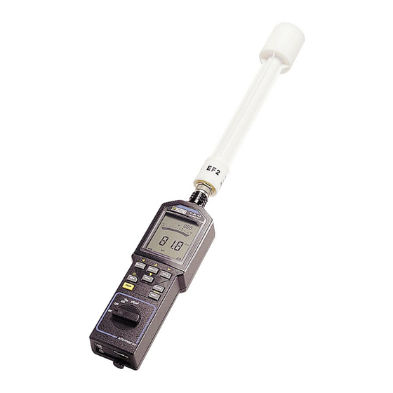
PROCEDURE D’EMPLOI Raccorder la sonde de mesure adéquate sur le C.A 43. La connexion s’effectue par la prise multicontact située en haut de l’appareil. - Positionner la sonde dans l’axe du boîtier, - Tourner la sonde jusqu’au détrompage (point dur), - Enfoncer la sonde et tirer la bague de verrouillage (push-pull) vers le boîtier jusqu’à... -
Page 28: Sonde Ef2
SONDE EF2 La sonde EF2, livrée avec le C.A 43 étant isotropique, elle ne nécessite pas de manipulations spéciales. Son élément sensible mesure le champ selon 3 axes, sans avoir à déplacer la sonde dans les trois plans. Il suffit de pointer la cible pour effectuer la mesure. SONDE EF1 La sonde EF1, livrée en acces- soire est anisotropique. -
Page 29: Sortie Numérique
SORTIE NUMERIQUE Le C.A 43 dispose d’une sortie numérique. Cette interface bi-directionnelle permet à l’appareil de communiquer avec des périphériques extérieurs. Pour relier l’appareil, utiliser la fibre optique et l’adaptateur opto-électrique. Celui-ci trans- forme le signal optique en signal électrique exploitable. La fibre optique se connecte sur la sortie COM de l’appareil (détrompeur). -
Page 30: Interrogation A Distance
Protocole de transmission : pseudo X ON / X OFF La transmission se fait sur deux fibres optiques : - RxD Réception des données - TxD Transmission des données Cette interface permet la transmission des résultats de mesure, du contenu des mémoires programme ou mesure et de l’état de l’appareil. -
Page 31: Interrogation De La Mesure
La commande à distance ne peut pas démarrer la fonction impression automatique. La commande à distance ne peut pas réveiller l’appareil qui s’est endormi après 10 minutes de fonctionnement sans manipulation. Il y a cinq types d’interrogation à distance possibles décrites dans les paragraphes suivants. INTERROGATION DE LA MESURE Codes à... -
Page 32: Interrogation De La Mémoire Mesure
Le deuxième groupe contient l’état de la fonction sur 3 caractères : - LO AL et HI AL si l’alarme n’est pas activée si l’alarme est activée - - - si l’alarme n’est pas en service - BAT Chiffre correspondant à l’autonomie restante de la pile en %. C’est le même chiffre qui est annoncé... -
Page 33: Interrogation De La Mémoire Programme
Si pendant la sortie des informations, le commutateur rotatif est manipulé, la sortie est interrompue. Les touches sont inopérantes durant toute la sortie des informations. Pour arrêter la sortie des informations, il faut placer le commutateur rotatif sur OFF. INTERROGATION DE LA MEMOIRE PROGRAMME Cette fonction est accessible dans tous les modes de fonctionnement. -
Page 34: Exemple D'interrogation Rapide
L’interrogation de la mesure PEAK est obtenue en envoyant un code différent suivant le type de PEAK désiré : - pour obtenir la valeur PEAK MAX 250 µs (mesure 250 µs maximale effectuée pendant une mesure 20 ms), il faut envoyer le code : - 23 Hexa, 35 décimal Graphisme correspondant : # - pour obtenir la valeur de PEAK MIN 250 µs (valeur minimale effectuée pendant une mesure... - Page 35 p=0 : dim X1(200) ‘tableau des mesures à récupérer gosub ROUTINE01 gosub ROUTINE02 print:print «Saisie de 100 mesures...(cf pictogramme ‘COM’ de l’appareil)» beep for N=1 to 100 delay 0.08 ‘ ajoute 20 mS pour de temps de traitement du C.A 43 gosub ROUTINE03 X1(N)=K next N...
-
Page 36: Démodulation Sonore
DEMODULATION SONORE La fonction démodulation permet l’écoute, sur un haut parleur interne, de la modulation d’amplitude éventuellement présente sur le signal HF. Cette détection de modulation est limitée aux fréquences audibles, comprises entre 500 Hz et 5 kHz. Le meilleur rendement est obtenu pour des champs mesurés compris entre 5 V/m et 30 V/ m, avec une profondeur de modulation de 50 % minimum. -
Page 37: Caractéristiques
CARACTERISTIQUES CARACTERISTIQUES ELECTRIQUES Etendu de mesure : FONCTION ETENDUE DE MESURE V / m 0,1 à 199,9 µW / cm² 0,1 à 1999 A / m 0,1 à 19,99 Bande passante : de 100 kHz à 2,5 GHz La mesure de 100 kHz à 1 MHz est purement indicative. Domaine de mesure spécifié... - Page 38 Variation dans le domaine d’utilisation Grandeur d’influence Limite du domaine Grandeur influencée Variation MAX Température de 0 à 50 °C Toutes grandeurs 0,3 % / °C ambiante de la lecture ± 0,5 V/m par 10°C Humidité de 10 à 90 % Toutes grandeurs <...
-
Page 39: Caractéristiques Mécaniques
Alimentation L’alimentation de l’appareil est réalisée au moyen d’une pile 9 V de type 6 LF 22. Plage de tension assurant un fonctionnement correct : 6,5 V à 11 V. - Affichage du symbole clignotant pour une tension pile < 7,5 V (autonomie restante environ 1 heure). -
Page 40: Entretien
ENTRETIEN CHANGEMENT DE PILE Avant d’effectuer une mesure, s’assurer, en mettant en marche l’appareil, que le symbole de pile n’apparaît pas sur l’afficheur. Dans l’affirmative, il faut impérativement changer la pile. L’opérateur dispose d’une minute pour effectuer les opérations de changment de pile pour ne pas devoir refaire la mise à... -
Page 41: Garantie
GARANTIE Sauf dérogation contraire, nos instruments sont garantis contre tout défaut de fabrication ou de matière. Ils ne comportent pas la spécification dite de sécurité. Notre garantie, qui ne saurait en aucun cas excéder le montant du prix facturé, ne va pas au-delà de la remise en état de notre matériel défectueux, rendu franco à... - Page 42 Ce chiffre correspond à 80 mesures 250 µs. Pour obtenir la mesure 250 µs, il faut donc diviser le chiffre obtenu par 80. La mesure devient 316352/80 = 2802,4 La mesure ainsi calculée doit être linéarisée selon la formule suivante pour obtenir la vraie mesure : Mesure = Xa + b Les coefficients a et b sont donnés dans le tableau ci-après ils sont fonctions du type de sonde...
- Page 43 Chaque table contient 6 droites de linéarisations qui sont données pour les tables 2, 3, 4 et 5 (nous consulter si besoin pour les autres tables). Les valeurs début de pente et fin de pente correspondent aux valeurs de mesure disponibles en interrogation rapide des mesures.
- Page 44 Coefficient de la table 04 sonde EF2 première sensibilité : N° de droite début coef a coef b 0 pt 27 pts 5,925 10e-2 27 pts 143 pts 1,207 10e-2 1,274 143 pts 572 pts 6,993 10e-3 2,000 572 pts 2544 pts 3,651 10e-3 3,911...
- Page 45 English...
-
Page 46: Safety Precautions
SAFETY PRECAUTIONS Medical standards consider that electric fields greater than 60V/m can be dangerous to persons. The user must therefore avoid remaining in close proximity to the instrument when in an environment of this kind. Before making a measurement, as soon as the instrument is switched on, check that the low battery symbol (35) is not shown on the display. - Page 47 CONTENTS DESCRIPTION - Case - Display PRESENTATION - General - User manual labels SPECIAL FUNCTIONS - Switching On permanent - Switching Off the sound beep - Displaying the present time - Printing the program memory - Erasing the program memory - Erasing the measurement memory - Access to several special functions MEASUREMENT MODE...
- Page 48 (cont.) DIGITAL OUTPUT REMOTE READ - Reading the measurement - Reading the state of the instrument - Reading the measurement memory - Reading the program memory - Fast reading of the memory - Example of rapid read SOUND DEMODULATION SPECIFICATIONS - Electrical specifications - Mechanical specifications MAINTENANCE...
-
Page 49: Description
DESCRIPTION CASE 1 - Sound demodulation control 2 - Optical connector, digital link 3 - 4 position rotary switch button PRGM - Programming - Initialisation of the program memory button - Memorisation of the measurement - Display of the memory address - Display of the remaining memory capacity - Initialisation of the measurement memory ¿... -
Page 50: Display
11 - button ALARM - On/Off alarm detection - Selection of low and high alarms on programming - Display of the alarms on re-reading measurement memory PRINT 12 - button - Printout SCAN button - Programming print rate. DISPLAY 13 - Programming mode in operation 14 - Printout request mode 15 - Clock 16 - Cancel automatic memorisation... - Page 51 30 - Re-read measurement memory mode 31 - Memorisation of measurements 32 - Recording MIN, MAX and AVG in operation 33 - Instrument in permanent operation 34 - Digital readout of the average value 35 - Low battery indicator 36 - Digital readout of the minimum value 37 - "Beep"...
-
Page 52: Presentation
PRESENT PRESENT A A A A A TION PRESENT TION TION TION PRESENT PRESENT TION GENERAL Pollution of the radio-electric environment is becoming more and more harsh, which leads to problems of malfunctioning in many types of electronic equipment, especially since the use of sequential logic and the development of microprocessors. -
Page 53: User Manual Labels
USER MANUAL LABELS Five adhesive labels are supplied with your Fieldmeter. They are simplified reminders about how to use your instrument. This information is available in five languages. Choose your label and carefully stick it to the back of your instrument. Now you will always have the information necessary to use your Fieldmeter. -
Page 54: Special Functions
SPECIAL FUNCTIONS SWITCHING ON PERMANENTLY After 10 minutes of operation without pressing a button or turning the rotary switch or reading the digital output, a battery economy system puts the instrument to sleep. This auto Off is preceded by a beep and flashing of the digital display for one minute. If you operate the instrument whilst it is flashing, the instrument will continue its active operation for a further period of 10 minutes in the selected functions and without taking into account the button pressed to wake it up. -
Page 55: Displaying The Present Time
These beeps can be suppressed if they seem too noisy to you. To do this, simultaneously press as you switch On with the rotary switch. The disappearance of the MIN MAX symbol from the screen shows that the beep is switched Off. This deactivation of the beep will be continued even after the instrument is switched Off (switch to the OFF position). - Page 56 This is done via the TxD output by a series of data consisting of three groups of four lines, giving the four values programmed for each measurement unit. At the end of this transmission the instrument returns to the measurement function and the COM symbol disappears. The presentation of the results is done in superimposed lines, each line corresponds to a programmed function.
-
Page 57: Erasing The Program Memory
When the instrument is switched On during initialisation of the program, the instrument may send false data to the serial output, symbolised by the code "error 4" (ER4). ERASING THE PROGRAM MEMORY To initialise the programme memory, press simultaneously when switching On PRGM with the rotary switch and continue to press until it disappears. -
Page 58: Measurement Mode
MEASUREMENT MODE Whatever the measurement mode, the sampling time is always 250µs. The table below summarizes the measurement times of the various modes described in this chapter. Measurement mode Symbol Digital measurement time Normal measurement 400 ms Recording (of MIN, MAX and AVG) RECORD 400 ms Smooth measurement... -
Page 59: Min Max , Average Recording
The 50Hz filter for rejection of low frequency fields is suppressed. The C.A 43 becomes sen- sitive to the power supplies of electric equipment, mains cable runs,... A first press on switches On the function and the PEAK symbol appears on the display. PEAK - The bargraph indicates the average value of the four highest peak values measured over 100ms. - Page 60 Reading the MAX, MIN and AVG values The display of the values contained in the MAX, MIN and AVG registers is done by successive presses on MIN MAX The cycle of the display successively indicates the maximum value reached (MAX symbol), the minimum value reached (MIN symbol), the average value (AVG symbol) then the value of the current measurement and so forth.
-
Page 61: Alarm On/Off
Press again to stop recording MIN, MAX and AVG values : HOLD - The HOLD and PAUSE symbols disappear. - The digital display indicates the current measurement or the contents of the MIN, MAX or AVG registers on read mode. - The instrument is again on MIN, MAX and AVG mode but the registers have not yet been reinitialised and they contain the MIN, MAX and AVG values present before HOLD was used. - Page 62 symbols, or both, light up on the display depending on the type of threshold programmed. On the bargraph, the segments correspond to the thresholds shown in reverse contrast. When the alarms are On, a second press on switches Off the alarm function (the ALARM alarm symbols disappear).
-
Page 63: Memory Mode
MEMORY MODE It is possible to enter measurements in the memory when the selector switch is on one of the two measurement positions: V/m (A/m) or µW/cm². The memory can be accessed and read when the switch is set to MR. MANUAL MEMORY A single press on allows you to store all the parameters of the measurement that... -
Page 64: Reading Measurement Memory
Note : If the value of Dt is not programmed (symbolised by three hyphens on the Dt programming), the memorisation does not function and the MEM symbol is not displayed. Each memorisation is dated. This date, recorded in HH MM, also corresponds to a particular memory address. - Page 65 On read memory mode, the PEAK button changes to its second function as indicated by the symbol printed on the case. This second function allows you to decrease the different addresses of the measure- ment memory, each press moves back the read address by one. If the read address contains a manual memorisation, the display will indicate all the parameters present at the time of memorisation.
- Page 66 The alarms can be switched On or Off during the read function by simply ALARM pressing ALARM, the type of alarm programmed is shown on the display ( symbols). Each press on allows you to directly access the value beyond the next threshold.
-
Page 67: Print Mode
PRINT MODE MANUAL PRINTOUT On measurement function or memorisation function, each press on transmits PRINT to the TxD optical output a series of data in the following form: <Time> <Filter> <Function> <Measurement> <Unit> Each group is separated by 1 space. The output of the five groups is ended by a carriage return and 2 line paper advance. -
Page 68: Automatic Printout
AUTOMATIC PRINTOUT When the Scanning function (printout every n minutes) is programmed, press PRINT start the measurements printing cycle with the SCAN time interval programmed. This cycle starts by printing the measurement displayed when this command is sent. The SCAN symbol remains lit on the display throughout the duration of operation of the automatic printout mode. -
Page 69: Scan
In program mode (PRGM displayed), five values can be set by pressing different buttons : Press button Symbol on screen Low alarm 1st press ALARM High alarm 2nd press ALARM ¿ Memorisation session 1st press ¿ ¿ Current time 2nd press SCAN Print rate 1st press... -
Page 70: Special Cases In Μw/Cm²
When the digit furthest to the left is active, press to display three hyphens and the previously displayed value disappears. Idem for the button when the active digit is located on the far right of the display. Note : The increase of the digit on the left gives access to tens by carrying the remainder. The validation of "- - -"... -
Page 71: Operating Procedure
OPERATING PROCEDURE Connect the appropriate measurement probe to the C.A 43. The connection is made through the multicontact push-pull socket located at the top of the instrument. - Position the probe in the axis of the case, - Turn the probe to align the locking system, - Push the probe in and push the ring until it locks (clicks). -
Page 72: Ef2 Probe
PROBE EF2 As the EF2 probe is isotropic, it does not require special handling. Its sensitive part measures the field according to 3 axes without the aerial having to be moved in the 3 planes. Simply point it at the target to make the measurement. EF1 PROBE The EF1 probe supplied with the C.A 43 is anisotropic. -
Page 73: Digital Output
DIGITAL OUTPUT The C.A 43 has a digital output. This bi-directional interface allows the instrument to communicate with external peripherals. To connect the instrument, use the optic fibre and the opto-electric adaptor. This transforms the optic signal into a usable electric signal. The optic fibre connects to the COM output of the instrument (see lug for correct position). -
Page 74: Remote Read
Transmission protocol: pseudo X ON/X OFF The transmission is done on two optic fibres : - RxD Reception of data - TxD Transmission of data This interface allows the transmission of the results of the measurement, of the content of the program memory, or measurement of the state of the instrument. -
Page 75: Reading The Measurement
The remote control can not start the auto print function. The remote control can not wake up the instrument which has gone to sleep after 10 minutes of operation without being manipulated. There are five types of remote read possible described in the following paragraphs. READ MEASUREMENT Codes to send to the instrument to get the value of the instantaneous measurement : - 3F Hexa, 63 Decimal... -
Page 76: Reading The Measurement Memory
The second group contains the state of the function in 3 characters : - LO AL and HI AL OFF if the alarm is not On if the alarm is On - - - if the alarm is not in service - BAT Digit corresponding to the remaining service life of the battery in %. -
Page 77: Reading The Program Memory
If the rotary switch is operated during the output of information, the output is interrupted. The buttons are inoperative during all the output of information. To stop the data output, set the rotary switch to OFF. READ THE MEMORY PROGRAM This function is accessible in all operating modes. -
Page 78: Example Of Rapid Read
Reading the PEAK measurement is obtained by sending a different code according to the type of PEAK desired : - to obtain the PEAK MAX 250µs value (measures 250µs max made during a 20ms measurement), you must send the code : - 23 Hexa, 35 decimal Corresponding graphic: # to obtain the PEAK MIN 250µs value (minimum value during a 20ms measurement), you must... - Page 79 “==================== S U B - P R O G R A M S ======================= ROUTINE01: “table of sensor 231 (taken as example) B(1)=00000:F(1)=000033:CF(1)=4.666e-2:Q(1)=00.000 B(2)=00033:F(2)=000250:CF(2)=9.953e-3:Q(2)=01.211 B(3)=00250:F(3)=000820:CF(3)=5.438e-3:Q(3)=02.340 B(4)=00820:F(4)=002640:CF(4)=3.022e-3:Q(4)=04.322 B(5)=02640:F(5)=011776:CF(5)=1.893e-3:Q(5)=07.300 B(6)=11776:F(6)=143360:CF(6)=1.294e-3:Q(6)=14.360 return ROUTINE02: print "setting up of RS232 on COM1..." open "COM1:1200,N,8,1,RS" AS #1 return ROUTINE03: print #1,chr$(34);...
-
Page 80: Sound Demodulation
SOUND DEMODULATION The demodulation function allows the amplitude modulation which may be present on the HF signal to be heard on an internal loud speaker. This detection of modulation is limited to the audible frequencies between 500 Hz and 5 kHz inclusive. The best result is obtained for fields measured between 5 V/m and 30 V/m inclusive with a modulation depth of 50% minimum. -
Page 81: Specifications
SPECIFICATIONS ELECTRICAL SPECIFICATIONS Measurement extent : FUNCTION MEASUREMENT EXTENT V / m 0.1 to 199.9 µW / cm² 0.1 to 1999 A / m 0.1 to 19.99 Pass band: from 100kHz to 2.5GHz The measurement from 100kHz to 1MHz is purely indicative. Specified measurement domain : Measurements are taken in a distant field in order to obtain a flat wave. - Page 82 Variation in the operating range Distortion magnitude Limit of range Magnitude distorted MAX variation Ambient 0 to 50°C all magnitudes 0.3 % / °C temperature of the reading ± 0.5V/m per 10°C Humidity 10 to 90% < 0.5 V/m no condensation magnitudes Power supply 7.5 to 11 V...
-
Page 83: Mechanical Specifications
Power supply The power supply of the instrument is produced by a 9 V battery type 6 LF 22. Voltage range ensuring correct operation: 6.5 V to 11 V. - Display of symbol flashing for a battery voltage < 7.5 V (remaining service life approx. -
Page 84: Maintenance
MAINTENANCE CHANGING THE BATTERY Before making a measurement, check by switching On the instrument that the battery symbol is not visible on the display. If it is, you must change the battery. The user has one minute in which to change the battery without having to reset the clock. Open the battery compartment at the back of the instrument using a coin (tool release screw). -
Page 85: Warranty
WARRANTY Unless otherwise stated, our instruments are guaranteed against any manufacturing defect, or defective parts. They do not have "Safety" specification. Our guarantee, which may not under any circumstances exceed the amount of the invoiced price, will not extend beyond repair of our instruments, returned carriage paid to our workshops. - Page 86 This figure corresponds to 80 measurements of 250µs. To get the 250µs measurement, you must therefore divide the figure obtained by 80. The measurement becomes 316352/80 = 2802.4 The measurement thus calculated must be linearised according to the following formula to get the true measurement: Measurement = Xa + b The coefficients a and b are given in the table below, they depend on the type of probe used,...
- Page 87 Each table contains 6 linearisation straight lines which are given for tables 2, 3, 4 and 5 (consult us if necessary for the other tables). The values for the start of the slope and end of slope correspond to the measurement values available on rapid interrogation of measurement.
- Page 88 Coefficients of table 04 probe EF2 first sensitivity : N° straight line Start Coeff. a Coeff. b 0 ct 27 cts 5.925 10e-2 27 cts 143 cts 1.207 10e-2 1.274 143 cts 572 cts 6.993 10e-3 2.000 572 cts 2544 cts 3.651 10e-3 3.911 2544 cts...
- Page 89 Deutch...
-
Page 90: Sicherheitshinweise
SICHERHEITSHINWEISE In der Medizin wird die Ansicht vertreten, daß elektrische Felder mit einer Stärke von mehr als 60 V/m für den Menschen gefährlich sein können. Der Anwender sollte es daher vermeiden, in unmittelbarer Nähe des Gerätes zu bleiben, wenn sich dieses in einem solchen Feld befindet. - Page 91 INHALT BESCHREIBUNG - Gerät - Anzeige GERÄTEINFORMATIONEN - Allgemeines - Etiketten mit vereinfachter Bedienungsanleitung BETRIEB DES GERÄTES SONDERFUNKTIONEN - Dauerbetrieb - Abschalten des akustischen Signals - Anzeige der laufenden Uhrzeit - Ausdrucken des Programmspeichers - Löschen des Programmspeichers - Löschen des Meßwertspeichers - Gleichzeitiger Zugang zu mehreren Sonderfunktionen MESSEN - Festhalten des angezeigten Meßwertes...
- Page 92 (suite) DIGITALAUSGANG FERNABFRAGE - Meßwertabfrage - Abfrage des Gerätezustands - Abfrage des Meßwertspeichers - Abfrage des Programmspeichers - Schnelle Meßwertabfrage - Exemple d'interrogation rapide AKUSTISCHE DEMODULATION TECHNISCHE DATEN - Elektrische Charakteristiken - Mechanische Charakteristiken WARTUNG - Batteriewechsel - Reinigung - Wartung GARANTIE ANHANG...
-
Page 93: Beschreibung
BESCHREIBUNG GERÄT 1 - Schalter für akustische Demodulation 2 - Anschluß für Lichtleitfaser, digitale Datenleitung 3 - Drehschalter mit 4 Positionen 4 - Taste PRGM - Programmieren - Initialisieren des Programmspeichers 5 - Taste - Meßwertspeicherung - Anzeige der Speicheradresse - Anzeige der verbleibenden Speicherkapazität - Initialisieren des Meßwertspeichers ¿... -
Page 94: Anzeige
ALARM 11 - Taste - An-/Abschaltung der Alarmfunktion - Wahl der oberen und unteren Schwellwerte bei der Programmierung - Anzeige der Alarmwerte beim Abrufen des Meßwertspeichers PRINT 12 - Taste - Ausdruck SCAN Taste - Programmieren des Zeittakts für den Ausdruck von Meßwerten ANZEIGE 13 - Programmiermodus eingeschaltet 14 - Druckbefehl erteilt... - Page 95 30 - Abrufen des Meßwertspeichers 31 - Meßwertspeicherung 32 - Aufzeichnung von MIN, MAX und AVG eingeschaltet 33 - Gerät auf Dauerbetrieb geschaltet 34 - Digitalanzeige des Mittelwertes 35 - Batterieanzeige 36 - Digitalanzeige des Mindestwertes 37 - Akustisches Signal eingeschaltet 38 - Digitalanzeige des Höchstwertes 39 - Festhalten der Digitalanzeige 40 - Obere Alarmschwelle überschritten...
-
Page 96: Geräteinformationen
GERÄTEINFORMATIONEN ALLGEMEINES Die Verschmutzung des radioelektrischen Umfeldes nimmt immer aggressivere Formen an. Dadurch kommt es zu Fehlfunktionen bei zahlreichen elektronischen Einrichtungen, insbesondere seit der Verwendung sequentieller Logik und der Entwicklung der Mikroprozessoren. Diese modernen Techniken werden in praktisch allen Arten von Industriegeräten eingesetzt, was sie für elektromagnetische Störungen außerordentlich anfällig macht. -
Page 97: Etiketten Mit Vereinfachter Bedienungsanleitung
ETIKETTEN MIT VEREINFACHTER BEDIENUNGSANLEITUNG Ihr Feldstärkenmeßgerät wird mit fünf Klebeetiketten geliefert. Auf diesen Etiketten finden Sie eine sehr vereinfachte Version der Bedienungsanleitung in fünf Sprachen. Suchen Sie sich das Etikett in Ihrer Sprache heraus und kleben Sie es auf die Rückseite des Gerätes. Auf diese Weise haben Sie ständig die wichtigsten Informationen über die Handhabung Ihres Feldstärkenmeßgerätes zur Hand. -
Page 98: Sonderfunktionen
SONDERFUNKTIONEN DAUERBETRIEB Nach zehnminütiger Einschaltzeit ohne Betätigung einer Taste oder des Drehschalters oder Abfrage des Digitalausgangs wird das Gerät durch eine Batteriesparschaltung auf Sparbetrieb geschaltet. Dieser automatischen Abschaltung geht ein akustisches Signal voraus. Außerdem blinkt die Digitalanzeige für die Dauer einer Minute. Wenn während des Blinkens der Anzeige eine Taste des Gerätes betätigt wird, schaltet es für weitere 10 Minuten mit den vorgewählten Funktionen und ohne Berücksichtigung der «Wecktaste»... -
Page 99: Anzeige Der Laufenden Uhrzeit
Wenn Ihnen diese akustischen Signale zu laut sind, können Sie sie abschalten. Zu diesem Zweck betätigen Sie beim Einschalten des Gerätes mit dem Drehschalter gleichzeitig die Taste . Das Verschwinden des Symbols zeigt an, daß das akustische MIN MAX Signal abgeschaltet ist. Diese Abschaltung bleibt auch nach dem Abschalten des Gerätes (Drehschalter auf Position OFF) gespeichert. - Page 100 Diese Datenübertragung erfolgt am Ausgang TxD in Form einer Serie von Informationen, bestehend aus drei Gruppen à vier Zeilen mit den vier Werten, die für jede Meßeinheit programmiert wurden. Nach Abschluß der Übertragung kehrt das Gerät wieder in den Meßmodus zurück und das Symbol COM erlischt wieder in der Anzeige. Die Ergebnisse werden in Form von aufeinanderfolgenden Zeilen dargestellt, wobei jede Zeile einer programmierten Funktion entspricht.
-
Page 101: Löschen Des Programmspeichers
Beim Einschalten des Gerätes während der Initialisierung des Programms kann das Gerät eine Serie von Fehlinformationen absenden, die durch den Fehlercode 4 (ER4) angezeigt werden. LÖSCHEN DES PROGRAMMSPEICHERS Zum Initialisieren des Programmspeichers beim Einschalten anhand des Drehschalters gleichzeitig die Taste betätigen und bis zum Löschen des Speicherinhalts PRGM gedrückt halten. -
Page 102: Messen
MESSEN In jedem Meßmodus beträgt die Dauer der Meßwerterfassung stets 250µs. In der nachstehenden Tabelle sind die Meßzeiten der verschiedenen Meßverfahren zusammengefaßt, die in diesem Kapitel beschrieben werden. Meßmodus Symbol Digitale Meßzeit Normalmessung 400 ms Aufzeichning (MIN-, MAX-, und Mittelwerte) RECORD 400 ms Meßwertglättung... -
Page 103: Aufzeichnen Der Höchst-, Mindest- Und Mittelwerte
Der 50 Hz-Selektivfilter für NF-Felder wird unterdrückt. Das Meßgerät spricht an auf die Stromversorgung elektrischer Geräte, Netzkabel usw. Ein erster Druck auf die Taste schaltet die Funktion ein, und auf der Anzeige erscheint PEAK das Symbol PEAK. - Der Bargraph zeigt den Mittelwert der vier höchsten Spitzenwerte an, die während eines Zeitraums von 100 ms gemessen wurden. - Page 104 Auf diese Weise wird sekündlich der Inhalt des Registers AVG aktualisiert. Dieser Mittelwert kann als mittlere Dosis der über einen bestimmten Zeitraum gemessenen Felder angesehen werden (Dosimeter-Funktion). Der Zeitraum, über den eine Mittelwertbildung erfolgt ist, wird auf der Uhr in Stunden und Minuten angezeigt.
- Page 105 Ein weiterer Druck auf gibt die Aufzeichnung der Meßwerte für MIN, MAX und HOLD AVG wieder frei : - Die Symbole HOLD und PAUSE erlöschen. - Die Digitalanzeige zeigt den laufenden Meßwert oder den Inhalt der abgerufenen Speicherregister MIN, MAX oder AVG an. - Das Gerät befindet sich erneut im Modus MIN, MAX und AVG, aber die Register wurden nicht reinitialisiert und enthalten die gemessenen Werte für MIN, MAX und AVG vor Betätigen der Taste HOLD.
- Page 106 AN-/ABSCHALTEN DER ALARMFUNKTIONEN Wenn Schwellwerte programmiert worden sind, aktiviert ein Druck auf ALARM Feststellung von Überschreitungen dieser Schwellwerte. Die Symbole oder oder beide erscheinen auf der Anzeige, je nachdem, welcher Schwellwert programmiert worden ist. Auf dem Bargraph werden den Schwellwerten entsprechende Segmente, invertiert dargestellt.
-
Page 107: Speichern
SPEICHERN Die Speicherung von Meßwerten kann erfolgen, wenn sich der Drehschalter in einer der beiden aktiven Meßpositionen befindet: V/m (A/m) oder µW/cm². Ein Abrufen des Speicherinhaltes ist möglich, wenn der Drehschalter auf MR steht. MANUELLE MESSWERTSPEICHERUNG Mit Druck auf die Taste können im Meßwertspeicher alle Parameter der Messung gespeichert werden, die zum Zeitpunkt des Tastendrucks gegeben sind : <... -
Page 108: Abrufen Des Meßwertspeichers
Anmerkung : Wenn für Dt kein Wert programmiert worden ist (angezeigt durch drei waagerechte Striche bei der Programmierung von Dt), funktioniert die Meßwertspeicherung nicht, und das Symbol MEM wird nicht angezeigt. Jedem gespeicherten Meßwert ist eine Uhrzeit zugeordnet. Dieser Uhrzeit, angegeben in Stunden und Minuten, entspricht auch eine eigene Speicheradresse. - Page 109 Sie können : - entweder den gesamten Inhalt des Meßwertspeichers aufrufen, indem sie die einzelnen gespeicherten Meßwerte anhand der Tasten nacheinander aufrufen; - oder nur diejenigen gespeicherten Meßwerte aufrufen, die einen Alarm ausgelöst haben, indem sie zuvor die Taste betätigen. ALARM Beim Abrufen des Speicherinhalts schaltet die Taste PEAK auf die Zweitfunktion um, die anhand des Symbols...
- Page 110 Beim Abrufen des Speicherinhalts schaltet die Taste auf die Zweitfunktion SMOOTH um, die anhand des Symbols auf dem Gerät angezeigt wird. Ihre Funktion ist mit derjenigen der Taste analog, aber sie inkrementiert die Speicheradresse. Somit wird diese Taste inaktiv (akustisches Signal), wenn der Drehschalter auf MR gestellt wird, und der angezeigte Wert der letzten Speicheradresse entspricht.
-
Page 111: Ausdrucken
AUSDRUCKEN MANUELLES AUSDRUCKEN Wenn die Funktion Messen oder Speichern eingeschaltet ist, wird bei jedem Druck auf die Taste an den Ausgang TxD eine Serie von Informationen in folgender Form PRINT übermittelt : < Uhrzeit > < Filter > < Funktion > < Meßwert > < Maßeinheit > Die Datengruppen sind durch eine Leerstelle voneinander getrennt. -
Page 112: Automatisches Ausdrucken
AUTOMATISCHER AUSDRUCK Wenn die Funktion Scanning aktiv ist (Ausdruck im Abstand von jeweils n Minuten), wird durch Druck auf die Taste der Ausdruck der Meßwerte mit programmiertem SCAN- PRINT Zeitintervall gestartet. Der Zyklus beginnt mit dem Ausdruck des Meßwertes, der zum Zeitpunkt dieses Befehls angezeigt wird. -
Page 113: Eingeben Einer Zahl
Im Modus Programm (PRGM angezeigt) können fünf Parameter anhand verschiedener Tastenbetätigungen eingestellt werden : Tastendruck * Bildschirmsymbol Alarmschwelle unten 1. Tastendruck ALARM Alarmschwelle oben 2. Tastendruck ALARM ¿ Speichersitzung 1. Tastendruck ¿ ¿ Laufende Uhrzeit 2. Tastendruck Zeittakt des Ausdrucks 1. -
Page 114: Sonderfälle Bei Der Messung In Μw/Cm²
Wenn die ganz linke Ziffer aktiv ist, erscheinen bei Betätigung der Taste drei Striche und der vorher angezeigte Wert erlischt. Gleiches geschieht, wenn die Taste betätigt wird, während die am weitesten rechts befindliche Ziffer aktiv ist. Anmerkung : Durch Anheben der linken Ziffer gelangen Sie zu den Zehnerstellen mit Übertragung der gemerkten Zahl. -
Page 115: Inbetriebnahme
INBETRIEBNAHME Geeignete Meßsonde auf das C.A 43 aufstecken. Der Anschluß erfolgt anhand des Steckverbinders auf der Oberseite des Geräts. - Halten Sie die Meßsonde in gleicher Richtung wie das Gerät, - Drehen Sie die Sonde, bis Nut und Ausbuchtung übereinstimmen, - Stecken Sie die Sonde in das Meßgerät, bis sie einrastet (hörbares Klicken). -
Page 116: Sonde Ef2
SONDE EF2 Da die Sonde EF2, die zusammen mit dem C.A 43 geliefert wird isotropisch ist, benötigt sie keine besondere Handhabung. Ihr Meßelement mißt das Feld in drei Richtungen, ohne daß die Antenne in diesen drei Ebenen bewegt werden muß. Es genügt, das Ziel anzuvisieren, um die Messung vorzunehmen. -
Page 117: Digitalausgang
DIGITALAUSGANG Das Meßgerät C.A 43 besitzt einen Digitalausgang. Anhand dieser bidirektionalen Schnittstelle kann das Gerät mit Peripheriegeräten kommunizieren. Zum Anschluß des Gerätes sind der Lichtwellenleiter und der opto-elektronische Adapter zu verwenden. Dieser wandelt das optische Signal in ein verwertbares elektrische Signal um. Der Lichtwellenleiter wird an den COM-Ausgang des Gerätes angeschlossen (Verdrehungsschutz). -
Page 118: Fernabfrage
Übertragungsprotokoll : Pseudo X ON / X OFF Die Übertragung erfolgt anhand von zwei Lichtwellenleitern : - RxD Datenempfang - TxD Datenübertragung Dieses Interface ermöglicht die Übertragung der Meßergebnisse, des Inhalts der Programm- oder Meßwertspeicher und des Gerätezustands. Diese Übertragung erfolgt anhand eines Steuerbefehls. Dies kann ein lokaler Befehl, direkt am Gerät sein, oder ein Befehl, der von einer externen Steuereinheit erteilt wird. -
Page 119: Meßwertabfrage
Die Fernabfrage kann die Funktion automatischer Ausdruck nicht starten. Die Fernabfrage kann das Gerät nicht wecken, wenn es sich nach zehnminütiger Funktion ohne Tastenbetätigung in den Stromsparbetrieb geschaltet hat. Es gibt fünf Arten von Fernabfragen, die in den nachfolgenden Abschnitten beschrieben werden. -
Page 120: Abfrage Des Meßwertspeichers
Die zweite Gruppe enthält den Zustand der Funktion in Form von 3 Zeichen: - LO AL und HI AL OFF wenn der Alarm nicht aktiv ist wenn der Alarm aktiv ist — wenn der Alarm nicht in Betrieb ist - BAT Die Zahl entspricht der verbleibenden Betriebsdauer der Batterie in %. -
Page 121: Abfrage Des Programmspeichers
Wenn der Drehschalter während der Datenausgabe betätigt wird, wird die Ausgabe abgebrochen. Während der gesamten Datenausgabe sind die Tasten inaktiv. Um die Datenausgabe anzuhalten, ist der Drehschalter auf OFF zu stellen. ABFRAGE DES PROGRAMMSPEICHERS Diese Funktion ist von allen Betriebsarten aus zugänglich. Code, die an das Gerät gesendet werden müssen, um den Inhalt des Programmspeichers zu erfahren : - 2A Hexadezimal, 42 Dezimal... -
Page 122: Exemple D'interrogation Rapide
Die Abfrage des Spitzenmeßwerts PEAK erhält man durch Absendung eines unterschiedlichen Codes je nach gewünschtem Typ von PEAK : Um den Wert PEAK MAX 250 µs zu erhalten (maximale 250µs-Messung während einer 20 ms-Messung), ist folgender Code zu senden : - 23 Hexadezimal, 35 Dezimal graphisches Zeichen : # Um den Wert PEAK MIN 250 µs zu erhalten (Mindestwert während einer 20 ms-Messung),... - Page 123 p=0 : dim X1(200) “Tabelle der zu übernehmenden Messungen gosub ROUTINE01 gosub ROUTINE02 print:print «Eingabe von 100 Messungen...(siehe Beschreibung der Funktion “COM”)» beep for N=1 to 100 delay 0.08 “ + 20 ms Verarbeitungszeit..gosub ROUTINE03 X1 (N) = K next N beep print : print «Anzeige der 100 eingegebenen Messungen :»...
-
Page 124: Akustische Demodulation
AKUSTISCHE DEMODULATION Anhand der Demodulationsfunktion können Sie sich mit Hilfe des eingebauten Lautsprechers eine eventuell vorhandene Amplitudenmodulation des HF-Signals anhören. Diese Modulationsfeststellung ist begrenzt auf hörbare Frequenzen zwischen 500 Hz und 5 kHz. Das beste Ergebnis wird erzielt bei gemessenen Feldern zwischen 5 V/m und 30 V/m mit einer Modulationstiefe von mindestens 50%. -
Page 125: Technische Daten
TECHNISCHE DATEN ELEKTRISCHE CHARAKTERISTIKEN Meßspanne : FUNkTION MESSBEREICH V / m 0,1 bis 199,9 µW / cm² 0,1 bis 1999 A / m 0,1 bis 19,99 Bandbreite : von 100 kHz bis 2,5 GHz Die Messung im Bereich von 100 kHz bis 1 MHz besitzt einen Hinweischarakter. Angegebener Meßbereich : Die Messungen erfolgen in einem entfernten Feld, um eine flache Welle zu erhalten. -
Page 126: Wartung
Veränderungen im Anwendungsbereich Einflußgröße Grenzen des beeinflußte Größe maximale Anwendungsbereiches Veränderung Umgebungs- von 0 bis 50 °C alle 0,3 % / °C temperatur der Anzeige ± 0,5 V/m bei 10°C Feuchtigkeit von 10 bis 90 % alle < 0,5 V/m ohne Kondensation Stromversorgung von 7,5 bis 11 V... -
Page 127: Mechanische Charakteristiken
Stromversorgung Die Stromversorgung des Geräts erfolgt anhand einer 9V-Batterie vom Typ 6 LF 22. Spannungsbereich, innerhalb dessen eine korrekte Funktion gewährleistet ist: 6,5 V bis 11 V. - Das Symbol blinkt bei einer Batteriespannung von weniger als 7,5 V (verbleibende Betriebsdauer ca. -
Page 128: Wartung
WARTUNG BATTERIEWECHSEL Vergewissern Sie sich beim Einschalten des Gerätes, daß das Batteriesymbol nicht auf der Anzeige erscheint. Andernfalls ist die Batterie unbedingt auszuwechseln. Sie verfügen über einen Zeitraum von einer Minute für den Austausch der Batterie. Nach Ablauf dieser Zeit muß die Uhr neu eingestellt werden. Batteriefach auf der Geräterückseite mit einer Münze öffnen (unverlierbare Schraube). -
Page 129: Garantie
GARANTIE Falls nichts anderweitiges vereinbart wurde, bezieht sich unsere Garantie ausschlieblich auf fehlerhafte Fertigungs- bzw. Materialfehler. Die Garantieansprüche können in keinem Fall den in Rechnung gestellten Betrag überschreiten und werden damit auf die Instandsetzung unserer defekten Geräte beschränkt. Letztere sind unseren Werkstätten frei Haus zuzustellen. Die Mängelhaftung gilt nur bei bestimmungsgemäber Verwendung unserer Geräte, jedoch nicht im Falle von fehlerhafter Montage, mechanische Einwirkungen, nachlässige und unvorschriftsmäbige Behandlung, Überlastung oder Überspannungen, fremdeingriffe. - Page 130 Diese Zahl entspricht 80 Messungen mit 250 µs. Um den Meßwert für 250 µs zu erhalten, ist diese Zahl somit durch 80 zu dividieren. Daraus ergibt sich der Meßwert 316352/80 = 2802,4 Der auf diese Weise berechnete Meßwert ist anhand der folgenden Formel zu linearisieren, um den echten Meßwert zu erhalten: Meßwert = Xa + b Die Koeffizienten a und b sind in der nachstehenden Tabelle angeben und abhängig von der...
- Page 131 Jede Tabelle enthält 6 Linearisierungsgeraden, die für die Tabellen 2, 3, 4 und 5 angegeben werden (für die übrigen Tabellen wenden Sie sich nötigenfalls an uns) Die Werte am Anfang und am Ende der Steigung entsprechen den Meßwerten, die bei einer Schnellabfrage der Meßwerte zur Verfügung stehen.
- Page 132 Koeffizient der Tabelle 04 Sonde EF2 erste Empfindlichkeit : N° der Geraden Anfang Ende Koeff. a Koeff. b 0 Pkte 27 Pkte 5,925 10e-2 27 Pkte 143 Pkte 1,207 10e-2 1,274 143 Pkte 572 Pkte 6,993 10e-3 2,000 572 Pkte 2544 Pkte 3,651 10e-3 3,911...