Table des Matières

Publicité

Les langues disponibles

Les langues disponibles

Liens rapides

OPERATOR'S MANUAL
MANUEL D'UTILISATION
MANUAL DEL OPERADOR
7-1/4 in. COMPOUND MITER SAW
Double insulated
SCIE À ONGLETS COMPOSÉS DE
184 mm (7-1/4 po), Double isolation
SIERRA INGLETEADORA COMPUESTA
DESLIZANTE DE 184 mm (7-1/4 pulg.),
Doble aislamiento
TS1143L
TABLE OF CONTENTS
 General Safety Rules .......................2-3
 Specific Safety Rules ......................3-4
 Symbols ..............................................5
 Electrical .............................................6
 Glossary .............................................7
 Features .........................................8-10
 Tools needed .................................... 10
 Loose Parts ......................................11
 Assembly .....................................12-18
 Operation .....................................19-25
 Adjustments ................................26-27
 Maintenance .....................................28
 Parts Ordering / Service ......Back page
To reduce the
risk of injury, the user must read and
understand the operator's manual
before using this product.
SAVE THIS MANUAL FOR
FUTURE REFERENCE

TABLE DES MATIÈRES

 Symboles ............................................5
 Glossaire .............................................7
 Caractéristiques ............................8-10
 Outils nécessaires ............................ 10
 Assemblage .................................12-18
 Utilisation .....................................19-25
 Réglages ......................................26-27
 Entretien ...........................................28
 Commande de pièces
et dépannage ....................Page arrière
réduire les risques de blessures,
l'utilisateur doit lire et veiller à bien
comprendre le manuel d'utilisation avant
d'employer ce produit.
CONSERVER CE MANUEL
POUR FUTURE RÉFÉRENCE
ÍNDICE DE CONTENIDO
 Reglas de seguridad generales .......2-3
 Reglas de seguridad específicas ....3-4
 Símbolos ............................................5
 Aspectos eléctricos ............................ 6
 Glosario de términos .......................... 7
 Características ..............................8-10
 Herramientas necesarias .................. 10
 Lista de piezas sueltas ..................... 11
 Armado ........................................12-18
 Funcionamiento ...........................19-25
 Ajustes .........................................26-27
 Mantenimiento .................................. 28
 Pedidos de piezas
y servicio ....................... Pág. posterior
Pour
ADVERTENCIA:
el riesgo de lesiones, el usuario debe leer
y comprender el manual del operador
antes de usar este producto.
GUARDE ESTE MANUAL
PARA FUTURAS CONSULTAS
Para reducir

Publicité

Table des Matières
loading

Sommaire des Matières pour Ryobi TS1143L

  • Page 1: Table Des Matières

    SCIE À ONGLETS COMPOSÉS DE 184 mm (7-1/4 po), Double isolation SIERRA INGLETEADORA COMPUESTA DESLIZANTE DE 184 mm (7-1/4 pulg.), Doble aislamiento TS1143L TABLE OF CONTENTS TABLE DES MATIÈRES ÍNDICE DE CONTENIDO  General Safety Rules .......2-3  Règles de sécurité générales ..2-3 ...
  • Page 2: General Safety Rules

    GENERAL SAFETY RULES  SECURE WORK. Use clamps or a vise to hold work WARNING: when practical, it is safer than using your hand and frees both hands to operate the tool. Read and understand all instructions. Failure to follow ...
  • Page 3: Specific Safety Rules

    GENERAL SAFETY RULES  NEVER USE IN AN EXPLOSIVE ATMOSPHERE.  USE ONLY CORRECT BLADES. Do not use blades with Normal sparking of the motor could ignite fumes. incorrect size holes. Never use blade washers or blade bolts that are defective or incorrect. The maximum blade ...
  • Page 4 SPECIFIC SAFETY RULES  IF THE POWER SUPPLY CORD IS DAMAGED, it must  NEVER reach behind, under, or within three inches of the be replaced only by the manufacturer or by an authorized blade and its cutting path with hands and fingers for any reason.
  • Page 5: Symbols

    SYMBOLS The following signal words and meanings are intended to explain the levels of risk associated with this product. SYMBOL SIGNAL MEANING Indicates an imminently hazardous situation, which, if not avoided, will result DANGER: in death or serious injury. Indicates a potentially hazardous situation, which, if not avoided, could result WARNING: in death or serious injury.
  • Page 6: Electrical

    ELECTRICAL EXTENSION CORDS DOUBLE INSULATION When using a power tool at a considerable distance from Double insulation is a concept in safety in electric power tools, a power source, be sure to use an extension cord that has which eliminates the need for the usual three-wire grounded the capacity to handle the current the product will draw.
  • Page 7: Glossary

    GLOSSARY OF TERMS Anti-Kickback Pawls (radial arm and table saws) Push Blocks (for jointer planers) A device which, when properly installed and maintained, Device used to feed the workpiece over the jointer planer is designed to stop the workpiece from being kicked back cutterhead during any operation.
  • Page 8: Features

    FEATURES PRODUCT SPECIFICATIONS Cutting Capacity with Miter at 0°/Bevel 0°: Maximum lumber sizes ..... 1-1/2 in. x 4-1/4 in. Arbor ................. 5/8 in. Cutting Capacity with Miter at 45°/Bevel 0°: Blade Diameter ............7-1/4 in. Maximum lumber sizes ......1-1/2 in. x 3 in. No Load Speed ........
  • Page 9 FEATURES KNOW YOUR COMPOUND MITER SAW See Figures 1 - 5. The safe use of this product requires an understanding of the information on the tool and in this operator’s manual as well as a knowledge of the project you are attempting. Before use of this product, familiarize yourself with all operating features and safety rules.
  • Page 10: Spindle Lock Button

    FEATURES SELF-RETRACTING LOWER BLADE GUARD SWITCH SPINDLE TRIGGER The lower blade guard is made of shock-resistant, see- LOCK BUTTON through plastic that provides protection from each side of the blade. It retracts over the upper blade guard as the saw is lowered into the workpiece.
  • Page 11: Loose Parts

    LOOSE PARTS LIST The following items are included with your compound miter saw:  Miter Saw  Rear Bracket/Carrying Handle  Work Clamp  Dust Bag  Operator’s Manual  Blade Wrench  AAA Batteries (2) MITER SAW BATTERIES WORK CLAMP DUST BLADE...
  • Page 12: Assembly

    ASSEMBLY UNPACKING WARNING: This product requires assembly. Do not start the compound miter saw without checking  Carefully lift miter saw from the carton by the “D” handle for interference between the blade and the miter fence. and the saw base, and place it on a level work surface. Damage could result to the blade if it strikes the miter fence during operation of the saw and may result in WARNING:...
  • Page 13: Work Clamp

    ASSEMBLY INSTALLING THE REAR BRACKET/CARRYING HANDLE See Figure 9. CAUTION: A rear bracket is included with this miter saw to prevent tipping if the saw arm is released suddenly. Do not use this saw before installing the rear bracket/carrying handle and securely mounting the saw to a work surface or stand and may result in personal injury.
  • Page 14 ASSEMBLY INSTALLING BATTERIES FOR LASER LASER GUIDE See Figure 12. SWITCH BATTERIES  Remove screw from battery compartment cover using the Phillips end of the supplied blade wrench. Remove COMPARTMENT cover and set aside. COVER  Install two AAA batteries according to polarity indicators inside the battery compartment.
  • Page 15 ASSEMBLY TO INSTALL/REPLACE THE BLADE See Figures 14 - 15. SPINDLE LOCK BUTTON WARNING: A 7-1/4 in. blade is the maximum blade capacity of the saw. Never use a blade that is too thick to allow outer blade washer to engage with the flats on the spindle. Larger blades will come in contact with the blade guards, while thicker blades will prevent the blade bolt from se- curing the blade on the spindle.
  • Page 16 ASSEMBLY WARNING: SOCKET HEAD SCREW(S) Make sure the spindle lock button is not engaged before reconnecting saw into power source. Never engage spindle lock button when blade is rotating. NOTE: Many of the illustrations in this manual show only portions of the compound miter saw. This is intentional so that we can clearly show points being made in the illustra- tions.
  • Page 17 ASSEMBLY INDICATOR SCREW MITER SCALE SCALE INDICATOR INDICATOR BEVEL SCREW SCALE VIEW OF BLADE NOT SQUARE WITH FENCE, ADJUSTMENTS ARE REQUIRED Fig. 18 BLADE SQUARE SCALE Fig. 20 INDICATOR SOCKET HEAD COMBINATION SCREW(S) SQUARE MITER FENCE BLADE MITER TABLE VIEW OF BLADE NOT SQUARE WITH FENCE, ADJUSTMENTS ARE REQUIRED Fig.
  • Page 18 ASSEMBLY SQUARING THE BLADE TO THE MITER TABLE BLADE COMBINATION See Figures 19 - 23. SQUARE  Unplug the saw.  Pull the saw arm all the way down and engage the lock pin to hold the saw arm in transport position. BEVEL LOCK KNOB ...
  • Page 19: Operation

    OPERATION CUTTING WITH YOUR COMPOUND WARNING: MITER SAW Do not allow familiarity with tools to make you careless. Remember that a careless fraction of a second is sufficient WARNING: to inflict serious injury. When using a work clamp or C-clamp to secure your workpiece, clamp workpiece on one side of the blade WARNING: only.
  • Page 20 OPERATION  Before turning on the saw, perform a dry run of the cutting CROSS CUT operation just to make sure that no problems will occur when the cut is made.  Grasp the saw handle firmly. Depress the switch lock with thumb then squeeze the switch trigger.
  • Page 21 OPERATION  Grasp the saw handle firmly. Depress the switch lock COMPOUND MITER CUT with thumb then squeeze the switch trigger. Allow several seconds for the blade to reach maximum speed.  Slowly lower the blade into and through the workpiece. ...
  • Page 22 OPERATION  Place the workpiece flat on the miter table with one edge securely against the fence. If the board is warped, place the convex side against the fence. If the concave edge of a board is placed against the fence, the board could collapse on the blade at the end of the cut, jamming the blade.
  • Page 23: Cutting Compound Miters

    OPERATION CUTTING COMPOUND MITERS To aid in making the correct settings, the compound angle setting chart below has been provided. Since compound cuts are the most difficult to accurately obtain, trial cuts should be made in scrap material, and much thought and planning made, prior to making the required cut.
  • Page 24: Cutting Crown Molding

    OPERATION CUTTING CROWN MOLDING When setting the bevel and miter angles for compound miters, remember that the settings are interdependent; changing This compound miter saw does an excellent job of cutting one angle changes the other angle as well. crown molding. In general, compound miter saws do a better Keep in mind that the angles for crown molding are very job of cutting crown molding than any other tool made.
  • Page 25: Cutting Warped Material

    OPERATION Bevel Angle Type of Cut Setting Left side, inside corner 1. Top edge of molding against fence 33.85° 2. Miter table set right 31.62° 3. Save left end of cut Right side, inside corner 1. Bottom edge of molding against fence 33.85°...
  • Page 26: Adjustments

    ADJUSTMENTS POSITIVE STOP ADJUSTMENTS WARNING: See Figure 33. NOTE: These adjustments were made at the factory and Before performing any adjustment, make sure the tool is normally do not require readjustment. unplugged from the power supply. Failure to heed this warning could result in serious personal injury.
  • Page 27 ADJUSTMENTS DANGER: Laser radiation. Avoid direct eye contact with light source. LASER WARNING: ADJUSTMENT SCREW Use of controls or adjustments or performance of pro- cedures other than those specified herein can result in hazardous radiation exposure. TO ADJUST THE LASER GUIDE LASER See Figure 34.
  • Page 28: Maintenance

    MAINTENANCE WARNING: BRUSH When servicing, use only identical replacement parts. Use of any other parts can create a hazard or cause BRUSH product damage. ASSEMBLY WARNING: Always wear eye protection with side shields marked to comply with ANSI Z87.1. Failure to do so could result in BRUSH ASSEMBLY objects being thrown into your eyes, resulting in possible...
  • Page 29: Règles De Sécurité Générales

    RÈGLES DE SÉCURITÉ GÉNÉRALES  PORTER UNE TENUE APPROPRIÉE. Ne pas porter de AVERTISSEMENT : vêtements amples, cravates, ou bijoux susceptibles de se prendre et vous entraîner dans les pièces mobiles. Des Lire et veiller à bien comprendre toutes les gants en caoutchouc et des chaussures antidérapantes sont instructions.
  • Page 30: Règles De Sécurité Particulières

    RÈGLES DE SÉCURITÉ GÉNÉRALES  NE PAS MALTRAITER LE CORDON D’ALIMENTATION.  RESTER VIGILANT ET GARDER LE CONTRÔLE. Se Ne jamais utiliser le cordon d’alimentation pour transporter montrer attentif et faire preuve de bon sens. Ne pas utiliser l’outil et ne jamais débrancher ce dernier en tirant sur le l’outil en état de fatigue.
  • Page 31: Ne Jamais Faire Passer Le Commutateur De La Position Marche À La Position Arrêt

    RÈGLES DE SÉCURITÉ PARTICULIÈRES  S’ASSURER QUE LA LAME NE TOUCHE PAS LA PIÈCE. s’éloigner de la scie et attendre l’arrêt complet de la Ne jamais mettre la scie en marche si la lame touche la lame. Débrancher la scie de la prise secteur et resserrer pièce à...
  • Page 32: Symboles

    SYMBOLES Les termes de mise en garde suivants et leur signification ont pour but d’expliquer le degré de risque associé à l’utilisation de ce produit. SYMBOLE SIGNAL SIGNIFICATION Indique une situation extrêmement dangereuse qui, si elle n’est pas évitée, DANGER : aura pour conséquences des blessures graves ou mortelles.
  • Page 33: Caractéristiques Électriques

    CARACTÉRISTIQUES ÉLECTRIQUES DOUBLE ISOLATION CORDONS PROLONGATEURS La double isolation est un dispositif de sécurité utilisé sur les Lors de l’utilisation d’un outil électrique à grande distance outils à moteur électriques, éliminant le besoin de cordon d’une prise secteur, veiller à utiliser un cordon prolongateur d’alimentation habituel à...
  • Page 34: Glossaire

    GLOSSAIRE Blocs poussoirs (pour dégauchisseuses/raboteuses) Griffes antirebond (scies à table et radiales) Dispositifs qui, s’ils sont correctement installés et entretenus, Dispositif utilisés pour pousser le matériau contre la tête de coupe lors de toute opération. Ce dispositif aide à tenir la main sont conçus pour empêcher que la pièce coupée soit propulsée de l’opérateur bien à...
  • Page 35: Caractéristiques

    CARACTÉRISTIQUES FICHE TECHNIQUE Capacité de coupe avec onglet 45° / biseau 0° Dimensions maximum Axe ..................5/8 po de planches de bois .... 38 mm x 76 mm (1-1/2 po x 3 po) Diamètre de la lame............7-1/4 po Capacité de coupe avec onglet 0° / biseau 45° Vitesse à...
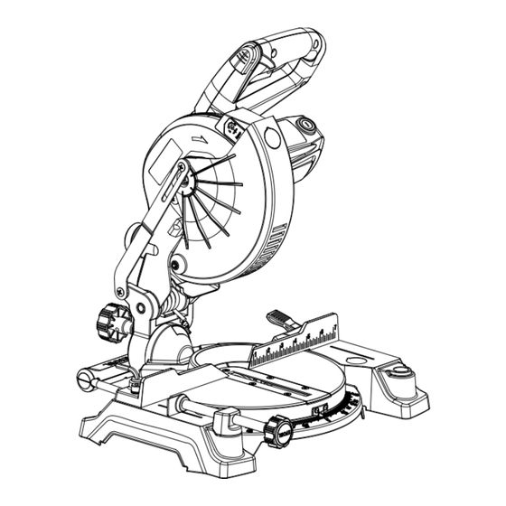
  • Page 36: Guide Laser

    CARACTÉRISTIQUES APPRENDRE À CONNAÎTRE LA SCIE À ONGLETS COMPOSÉS. Voir les figures 1 - 5. AXE DE BLOCAGE L’utilisation sûre de ce produit exige une compréhension des renseignements figurant sur l’outil et contenus dans le manuel d’utilisation, ainsi qu’une bonne connaissance du projet entrepris.
  • Page 37: Bouton De Verrouillage De Broche

    CARACTÉRISTIQUES BOUTON DE VERROUILLAGE DE BROCHE BOUTON DE GÂCHETTE Le bouton de verrouillage de broche verrouille la broche en VERROUILLAGE DE empéchant la lame de tourner. Maintenir le bouton enfoncé BROCHE pour l’installation, le changement ou la dépose de la lame. GÂCHETTE La scie ne se met en marche que lorsque le verrou de la commande est enfoncé...
  • Page 38: Liste Des Pièces Detachées

    LISTE DES PIÈCES DÉTACHÉES Les articles suivant sont fournis avec la scie à onglets composés :  Bride de serrage de pièce  Support arrière / poignée de  Scie à onglets transport  Clé à lame  Sac à poussiere  Manuel d’utilisation ...
  • Page 39: Assemblage

    ASSEMBLAGE DÉBALLAGE AVERTISSEMENT : Ce produit doit être assemblé. Ne pas mettre la scie en marche sans s’être assuré de  Soulever avec précaution la scie à onglets du carton l’absence d’interférence entre la lame et le guide d’onglets. d’emballage par la poignée en « D » et la base de la scie et La lame pourrait être endommagée si elle entrait en contact la poser sur un plan de travail horizontal.
  • Page 40: Installation De La Poignée De Soutien Et De Transport Arrière

    ASSEMBLAGE INSTALLATION DE LA POIGNÉE DE SOUTIEN ET DE TRANSPORT ARRIÈRE Voir la figure 9. ATTENTION : Cette scie à onglets est dotée d’un support arrière pour éviter son basculement si le bras de la scie est relâché soudainement. Ne pas utiliser cette scie avant d’avoir installé...
  • Page 41: Installation Des Piles Dans Le Laser

    ASSEMBLAGE INSTALLATION DES PILES DANS LE LASER INTERRUPTEUR Voir la figure 12. LASER PILES  Retirer la vis du couvercle du compartiment des piles à l’aide de l’extrémité à pointe cruciforme de la clé de lame COUVERCLE DU fournie. Retirer le couvercle et le mettre à l’écart. COMPARTIMENT ...
  • Page 42: Installation / Remplacement De La Lame

    ASSEMBLAGE Une fois familiarisé avec l’usage du laser, l’opérateur pourra effacer le tracé, le laisser ou effectuer la coupe sur celui-ci. La VERROUILLAGE DE pratique permettra de découvrir la position adéquate du trait BROCHE BOUTON laser par rapport au tracé. INSTALLATION / REMPLACEMENT DE LA LAME Voir les figures 13 et 14.
  • Page 43: Équerrage De La Lame Par Rapport Au Guide

    ASSEMBLAGE VIS À TÊTE CREUSE ATTENTION : DE FIXATION Toujours installer la lame avec les dents et la flèche imprimée sur son côté, orientées vers le bas à l’avant de la scie. Le sens de rotation de la lame est également représenté...
  • Page 44 ASSEMBLAGE LAME D’INDICATEUR VIS À TÊTE CREUSE DE FIXATION MITER INDICATEUR SCALE D’ÉCHELLE ÉCHELLE D’INDICATEUR DE BISEAU GUIDE D’ONGLET INDICATEUR ÉQUERRE D’ÉCHELLE TABLE À ONGLETS VUE DE LA LAME PAS D’ÉQUERRE AVEC LE GUIDE, DES RÉGLAGES SONT NÉCESSAIRES Fig. 18 INDICATEUR Fig.
  • Page 45: Équerrage De La Lame Par Rapport Àla Table À Onglets

    ASSEMBLAGE ÉQUERRAGE DE LA LAME PAR RAPPORT À LA TABLE À ONGLETS BOUTON DE VERROUILLAGE DE Voir les figures 19 à 22. BISEAU  Débrancher la scie.  Abaisser complètement le bras de la scie et engager l’axe de verrouillage pour maintenir le bras en position de transport. ...
  • Page 46: Utilisation

    UTILISATION TRAVAUX DE COUPE AVEC LA SCIE À AVERTISSEMENT : ONGLETS COMPOSÉS Ne pas laisser la familiarité avec l’outil faire oublier la AVERTISSEMENT : prudence. Ne pas oublier qu’une fraction de seconde d’inattention peut entraîner des blessures graves. Si un serre-joint ou une bride de serrage de pièce est utilisé pour maintenir la pièce, il ne doit être placé...
  • Page 47: Coupe En Biseau

    UTILISATION  Saisir la poignée de la scie fermement. Enfoncer le dispositif COUPE TRANSVERSALE de verrouillage avec le po puis serrer la gâchette.Attendre quelques secondes que la lame parvienne à sa vitesse de rotation maximum. BRIDE DE  Abaisser lentement la lame sur la pièce. SERRAGE DE ...
  • Page 48: Coupe D'onglet Composé

    UTILISATION  Saisir la poignée de la scie fermement. Enfoncer le COUPE D’ONGLET COMPOSÉ dispositif de verrouillage avec le po puis serrer la gâchette. Attendre quelques secondes que la lame parvienne à sa vitesse de rotation maximum.  Abaisser lentement la lame sur la pièce. ...
  • Page 49: Support De Pièces Longues

    UTILISATION  Avant de mettre la scie en marche, effectuer un essai à vide, afin de s’assurer qu’aucun problème ne se présentera lorsque la coupe est effectuée.  Saisir la poignée de la scie fermement. Enfoncer le dispositif de verrouillage avec le po puis serrer la gâchette. Attendre quelques secondes que la lame parvienne à...
  • Page 50: Coupe D'onglets Composés

    UTILISATION COUPE D’ONGLETS COMPOSÉS Le tableau des réglages d’angles ci-dessous est conçu pour faciliter les réglages. Les coupes composées étant les plus difficiles à réaliser, des essais doivent être effectués sur des chutes et la coupe définitive ne doit être effectuée qu’après mûre réflexion et planification.
  • Page 51: Coupe De Moulure Couronnée

    UTILISATION COUPE DE MOULURE COURONNÉE Lors du réglage des angles de biseau et d’onglet pour une coupe composée, ne pas oublier que les réglages des deux Cette scie à onglets composés est idéale pour la coupe de angles sont relationnels, la modification de l’un entraîne la moulures couronnées.
  • Page 52: Coupe De Pièces Voilées

    UTILISATION Réglage de l’angle de Type de coupe biseau Coin intérieur, côté gauche 1. Bord supérieur de la moulure contre le guide 33,85° 2. Angle d’onglet réglé à droite sur 31,62° 3. Conserver la section gauche de la pièce coupée. Coin intérieur, côté...
  • Page 53: Réglages

    RÉGLAGES RÉGLAGES DE BUTÉE POSITIVE AVERTISSEMENT : Voir la figure 33. NOTE : Ces réglages ont été effectués en usine et n’ont Avant d’effectuer tout réglage, s’assurer que l’outil est normalement pas besoin d’être refaits. débranché. Le non respect de cet avertissement pourrait entraîner des blessures graves.
  • Page 54: Réglage Du Laser

    RÉGLAGES DANGER : VIS DE RÉGLAGE Rayonnement laser. Éviter tout contact oculaire direct avec DE LASER la source du rayon. AVERTISSEMENT : L’usage de contrôles, de réglages ou de procédures ne figurant pas dans ce manuel peut entraîner l’exposition à des rayonnements dangereux.
  • Page 55: Entretien

    ENTRETIEN AVERTISSEMENT : Utiliser exclusivement des pièces identiques à celles COUVERCLE DE BALAI d’origine pour les réparations. L’usage de toute autre pièce pourrait créer une situation dangereuse ou BALAI endommager l’outil. AVERTISSEMENT : Toujours porter une protection oculaire avec écrans BALAI latéraux certifiée conforme à...
  • Page 56: Reglas De Seguridad Generales

    REGLAS DE SEGURIDAD GENERALES  VÍSTASE ADECUADAMENTE. Evite ponerse ropas ADVERTENCIA: holgadas, corbatas ni joyas que puedan engancharse y tirar de usted hacia las piezas en movimiento. Se recomiendan Lea y comprenda todas las instrucciones. El guantes y calzado antiderrapantes al trabajar al aire libre. incumplimiento de las instrucciones señaladas abajo puede Si tiene el pelo largo cúbraselo de alguna manera para causar descargas eléctricas, incendios y lesiones serias.
  • Page 57: Reglas De Seguridad Específicas

    REGLAS DE SEGURIDAD GENERALES  PROTÉJASE EL OÍDO. Durante períodos prolongados de  PERMANEZCA ALERTA Y EN CONTROL. Preste atención utilización de la unidad póngase protección para los oídos. a lo que esté haciendo y aplique el sentido común. No utilice la herramienta cuando esté...
  • Page 58 REGLAS DE SEGURIDAD ESPECÍFICAS  ASEGÚRESE DE QUE LA HOJA TRASPASE LA PIEZA DE  S I C U A L Q U I E R P I E Z A D E E S TA S I E R R A TRABAJO.
  • Page 59 SÍMBOLOS Las siguientes palabras de señalización y sus significados tienen el objeto de explicar los niveles de riesgo relacionados con este producto. SÍMBOLO SEÑAL SIGNIFICADO Indicates an imminently hazardous situation, which, if not avoided, will result PELIGRO: in death or serious injury. Indicates a potentially hazardous situation, which, if not avoided, could result ADVERTENCIA: in death or serious injury.
  • Page 60: Aspectos Eléctricos

    ASPECTOS ELÉCTRICOS DOBLE AISLAMIENTO CORDONES DE EXTENSIÓN El doble aislamiento es una característica de seguridad de las Al utilizar una herramienta eléctrica a una distancia herramientas eléctricas, la cual elimina la necesidad de usar considerable de la fuente de voltaje, asegúrese de utilizar el típico cordón eléctrico de tres conductores con conexión un cordón de extensión con la suficiente capacidad para a tierra.
  • Page 61: Glosario De Términos

    GLOSARIO DE TÉRMINOS Bloques empujadores (para cepillos de juntas) Trinquetes anticontragolpe (sierras radiales y de mesa) Es un dispositivo, el cual, cuando se instala y da mantenimiento Son dispositivos empleados para avanzar la pieza de trabajo por el cepillo de juntas durante cualquier operación. Este medio ayuda correctamente, sirve para detener la pieza de trabajo para no ser lanzada hacia atrás, hacia la parte frontal la sierra durante al operador a mantener las manos alejadas de la cabeza de corte.
  • Page 62: Características

    CARACTERÍSTICAS ESPECIFICACIONES DEL PRODUCTO Capacidad de corte con inglete a 45°/bisel a 0°: Tamaños máximos Árbol ................5/8 pulg. de la madera ....76 mm x 38 mm (3 pulg. x 1-1/2 pulg.) Diámetro de la hoja .............7-1/4 pulg. Capacidad de corte con inglete a 0°/bisel a 45°: Velocidad en vacío ..........
  • Page 63 CARACTERÍSTICAS FAMILÍCESE CON LA SI- ERRA INGLETEADORA COMBINADA Vea las figuras 1 a 5. El uso seguro que este producto requiere la comprensión de la información impresa en la herramienta y en el manual del operador así como ciertos conocimientos sobre el proyecto a realizar.
  • Page 64: Herramientas Necesarias

    CARACTERÍSTICAS PROTECCIÓN INFERIOR AUTORRETRAÍBLE GATILLO DEL BOTÓN DEL DE LA HOJA INTERRUPTOR SEGURO DEL La protección inferior de la hoja está hecha de plastico HUSILLO transparente resistente a impactos que proporciona pro- tección a cada lado de la hoja. Se retrae por encima de la protección superior a medida que se baja la hoja hacia la pieza de trabajo.
  • Page 65: Lista De Piezas Sueltas

    LISTA DE PIEZAS SUELTAS Vienen incluidos los siguientes artículos con la sierra ingleteadora combinada:  Sierra ingleteadora  Soporte trasero/mango de acarreo  Llave de hoja  Saco captapolvo  Manual del operador  Baterías AAA (2)  Prensa de trabajo SIERRA INGLETEADORA BATERÍAS PRENSA DE TRABAJO...
  • Page 66 ARMADO DESEMPAQUETADO ADVERTENCIA: Este producto requiere armarse.  Retire cuidadosamente la sierra ingleteadora de la caja, No encienda la sierra ingleteadora combinada sin revisar utilizando el mango en forma de “D” y la base de la sierra y para ver si hay interferencia entre la hoja y la guía de ingletes. colóquela sobre una superficie de trabajo a nivel.
  • Page 67 ARMADO INSTALACIÓN DEL SOPORTE TRASERO Y DEL MANGO DE ACARREO Vea la figura ADVERTENCIA: Con esta sierra ingleteadora se incluye un soporte trasero para evitar un volcamiento si se suelta súbitamente el brazo de la sierra. No use esta sierra sin haber instalado el soporte trasero/mango de acarreo y sin haber montado la sierra en una superficie de trabajo o base.
  • Page 68 ARMADO INSTALACIÓN DE LAS BATERÍAS EN EL LÁSER INTERRUPTOR Vea la figura 12. EL LÁSER BATERÍAS  Retire el tornillo de la cubierta del compartimiento de las baterías con la punta Phillips de la llave de la segueta CUBIERTA DEL provista.
  • Page 69 ARMADO PARA INSTALAR O REEMPLAZAR LA HOJA Vea las figuras 14 y 15. HUSILLO CON SEGURO BOTÓN ADVERTENCIA: La sierra tiene capacidad para hojas hasta de un diámetro de 7-1/4 pulg. Nunca utilice una hoja tan gruesa que la arandela exterior de la hoja no se enganche en las partes planas del husillo.
  • Page 70 ARMADO  Apriete firmemente el perno de la hoja. TORNILLO(S) DE  Vuelva a colocar la protección inferior y la tapa del perno CABEZA HUECA de la hoja.  Vuelva a colocar el tornillo de la cubierta del perno de la segueta y apriételo firmemente.
  • Page 71 ARMADO ARMADO TORNILLO DEL INDICADOR ESCALA DE INDICADOR DE INGLETES LA ESCALA TORNILLO DEL ESCALA DE INDICADOR BISELES VISTA DE LA HOJA FUERA DE ESCUADRA CON LA GUÍA, SE REQUIEREN AJUSTES Fig. 18 HOJA TORNILLO(S) DE CABEZA HUECA INDICADOR DE Fig.
  • Page 72 ARMADO ARMADO ESCUADRADO DE LA HOJA CON LA MESA PERILLA DE DE INGLETES HOJA FIJACIÓN DE Vea las figuras 19 a 23. BISEL  Desconecte la sierra.  Tire del brazo de la sierra completamente hacia abajo y enganche el pasador de seguridad para asegurar el brazo en la posición de traslado.
  • Page 73 FUNCIONAMIENTO FORMA DE CORTAR CON LA SIERRA ADVERTENCIA: INGLETEADORA COMBINADA No permita que su familarización con las herramientas lo vuelva descuidado. Tenga presente que un descuido de un ADVERTENCIA: instante es suficiente para causar una lesión grave. Al utilizar la prensa de trabajo o una de mano para asegurar la pieza de trabajo, sujete ésta sólo en un lado de la hoja.
  • Page 74 FUNCIONAMIENTO  Sujete firmemente el mango de la sierra. Oprima el seguro CORTE TRANSVERSAL del interruptor con el pulgar y luego oprima el gatillo. Permita transcurrir varios segundos para que la hoja alcance su velocidad máxima.  Baje lentamente la hoja de la sierra hacia la pieza de trabajo y corte ésta.
  • Page 75 FUNCIONAMIENTO  Sujete firmemente el mango de la sierra. Oprima el seguro CORTE EN INGLETE COMBINADO del interruptor con el pulgar y luego oprima el gatillo. Permita transcurrir varios segundos para que la hoja alcance su velocidad máxima.  Baje lentamente la hoja de la sierra hacia la pieza de trabajo y corte ésta.
  • Page 76 FUNCIONAMIENTO  Sujete firmemente el mango de la sierra. Oprima el seguro del interruptor con el pulgar y luego oprima el gatillo. Permita transcurrir varios segundos para que la hoja alcance su velocidad máxima.  Baje lentamente la hoja de la sierra hacia la pieza de trabajo y corte ésta.
  • Page 77 FUNCIONAMIENTO CÓMO EFECTUAR CORTES A INGLETE COMBINADOS Como ayuda para realizar los ajustes correctos, se suministra la siguiente tabla de ángulos combinados. Puesto que los cortes combinados son los más difíciles de obtener, deben efectuarse cortes de prueba en material de desecho, así como una gran cantidad de reflexión y planeación, antes de efectuar el corte final.
  • Page 78: Horizontal En La Mesa De Ingletes

    FUNCIONAMIENTO CÓMO CORTAR MOLDURAS DE CORONA Al fijar los ángulos de bisel e inglete de los cortes a inglete combinados, recuerde que los ajustes son interdependientes; Esta sierra ingleteadora combinada realiza una labor si se cambia un ángulo se cambia el otro también. excelente para cortes de molduras de corona.
  • Page 79 FUNCIONAMIENTO Ajuste del ángulo de bisel Tipo de corte Lado izquierdo, esquina interior 1. Canto superior moldura contra guía 33,85° 2. Mesa ingletes a 31,62° a la der. 3. Guarde extremo izquierdo del corte Lado derecho, esquina interior 1. Canto inferior moldura contra guía 33,85°...
  • Page 80 AJUSTES AJUSTES DE LOS TOPES ADVERTENCIA: Vea la figura 33. Antes de efectuar cualquier ajuste, asegúrese de que la NOTA: Estos ajustes se realizaron en la fábrica y normalmente herramienta esté desconectada del suministro de corri- no requieren reajustarse. ente. La inobservancia de esta advertencia podría causar Para ajustar: lesiones corporales serias.
  • Page 81 AJUSTES PELIGRO: Radiación láser. Evite todo contacto directo de los ojos con la fuente de luz. TORNILLO DE AJUSTE DEL LÁSER ADVERTENCIA: Todo control, ajuste o procedimiento diferente de los es- pecificados aquí, puede causar una exposición peligrosa a la radiación. PARA AJUSTAR LA GUÍA LASER CONJUNTO DE Vea la figura 34.
  • Page 82: Mantenimiento General

    MANTENIMIENTO ADVERTENCIA: TAPA DE LA ESCOBILLA Al dar servicio a la unidad, sólo utilice piezas de repuesto idénticas. El empleo de piezas diferentes puede causar un peligro o dañar el producto. CONJUNTO DE LA ESCOBILLA ADVERTENCIA: Cuando utilice este producto, siempre póngase protección ocular con protección lateral con la marca de CONJUNTO DE cumplimiento de la norma ANSI Z87.1.
  • Page 83 CALIFORNIA PROPOSITION 65 WARNING: This product and some dust created by power sanding, sawing, grinding, drilling, and other construction activities may contain chemicals, including lead, known to the State of California to cause cancer, birth de- fects, or other reproductive harm. Wash hands after handling. Some examples of these chemicals are: •...
  • Page 84 Please obtain your model and serial number from the product data plate. MODEL NUMBER _______________ SERIAL NUMBER ____________________________ RYOBI is a registered trademark of Ryobi Limited and is used pursuant to a license granted by Ryobi Limited. Pour faire une demande de réparations ou obtenir des pièces de rechange, trouver un Centre de réparations agréé...

Table des Matières