Jeulin Fibroptonic Mode D'emploi
Optique géométrique

Manuels Connexes pour Jeulin Fibroptonic

Sommaire des Matières pour Jeulin Fibroptonic
- Page 1 Optique Optique géométrique Optics Geometric optics Réf : 202 012 Fibroptonic Français – p 1 Fibroptonic English – p 38 Version : 9101...
- Page 2 Optique Fibroptonic Ref : 202 012 Cet ensemble d’accessoires optoélectroniques permet d’illustrer et d’étudier : • L’émission de signaux, • Leur transmission par fibre optique • Leur réception Il permet aussi de déterminer la fréquence de divers phénomènes vibratoires. Les manipulations proposées sont simples et souvent spectaculaires. Elles sont du niveau lycée à...
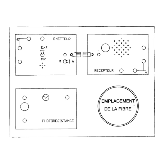
- Page 3 Optique Fibroptonic Ref : 202 012 Figure 1 : Le module émetteur Figure 2 : Le module récepteur Figure 3 : Le module photorésistance FRANCAIS...
-
Page 4: Mise En Service
Optique Fibroptonic Ref : 202 012 2 Mise en service ❖ Alimentation : Les deux modules émetteur et récepteur doivent être alimentés par un générateur délivrant une tension continue et constante dont la valeur est comprise entre 6 et 12 volts. Il est donc possible de les alimenter avec un seul générateur, même s'il est plus pédagogique de bien... -
Page 5: Comment Couper Une Fibre Optique
Optique Fibroptonic Ref : 202 012 2.1 Comment couper une fibre optique • Les 2 extrémités de la fibre ont été minutieusement dénudées et dépolies. Mais si pour une raison quelconque, on désire la couper, il faut retailler soigneusement l’extrémité sectionnée. -
Page 6: Service Après-Vente
Pour tous réglages, contacter le Support Technique au 0 825 563 563. Le matériel doit être retourné dans nos ateliers et pour toutes les réparations ou pièces détachées, veuillez contacter : JEULIN – S.A.V. 468 rue Jacques Monod CS 21900... - Page 7 Optique Fibroptonic Ref : 202 012 PROPAGATION D’UN SIGNAL FICHE FIBROPTONIC INFRAROUGE DANS L’AIR 1 But Expérimentation sur la propagation d’un signal infrarouge dans l’air et les milieux transparents Le photoémetteur délivre un signal infrarouge d'une centaine de nanomètres de largeur spectrale, centré...
-
Page 8: Montage Et Manipulation
Optique Fibroptonic Ref : 202 012 2.2 Montage et manipulation • alimenter l'émetteur et le récepteur (relier les bornes rouges au + du générateur et les bornes noires au -). • mettre l'interrupteur situé à côté du connecteur de l'émetteur sur M (marche), la DEL verte doit s'allumer et si l'on regarde à... -
Page 9: Montage
Optique Fibroptonic Ref : 202 012 PROPRIETES OPTIQUES ET FICHE GEOMETRIQUES D’UN FAISCEAU FIBROPTONIC INFRAROUGE 1 But Etudier la directivité d'un faisceau infrarouge et ses propriétés optiques Détection acoustique. 2 Expérience N° 2 Propagation rectiligne d’un faisceau infrarouge 2.1 Matériel •... - Page 10 Optique Fibroptonic Ref : 202 012 2.3 Manipulation Après avoir réglé le potentiomètre du boîtier récepteur au gain maximal, on essaie d'aligner le photorécepteur et le photoémetteur. Lorsque ceux-ci sont parfaitement alignés, un signal sonore retentit même si l'écart entre les connecteurs bleu et noir atteint 10 à...
- Page 11 Optique Fibroptonic Ref : 202 012 4 4 Expérience N° 4 Réfraction d’un faisceau infrarouge. Détection acoustique Par rapport à la manipulation précédente, il suffit de remplacer le miroir plan par un prisme ou un demi-cylindre en plexiglas ou en verre. L'angle au sommet du prisme doit être de 30 ou 45°...
-
Page 12: Observations Et Conclusion
Optique Fibroptonic Ref : 202 012 PROPAGATION D’UN SIGNAL FICHE FIBROPTONIC ELECTROMAGNETIQUE DANS UNE FIBRE OPTIQUE 1 But Transformation de signaux de nature différente, transport de l'information, visualisation. L'émetteur émet un signal infrarouge à 0,85 micromètre de longueur d'onde, mais l'information initiale, qui crée ce signal peut être de différente nature : électrique,... - Page 13 Optique Fibroptonic Ref : 202 012 3 Expérience N° 6 Transmission optique d’une information logique 3.1 Matériel • Emetteur • Récepteur • Fibre optique connectée à l'émetteur et au récepteur • Alimentation continue 6, 9 ou 12 V • Oscilloscope 3.2 Montage...
- Page 14 Optique Fibroptonic Ref : 202 012 FICHE FIBROPTONIC TELEPHONIE PAR FIBRE OPTIQUE 1 But Découvrir le principe de la téléphonie (transmission par fil) par fibre optique. 2 Expérience N° 7 2.1 Matériel • Emetteur • Récepteur • Fibre • Alimentation continue 6,9 ou 12 V 2.2 Manipulation...
- Page 15 Optique Fibroptonic Ref : 202 012 TRANSMISSION OPTIQUE D’UN FICHE FIBROPTONIC SIGNAL PERIODIQUE 1 But Illustrer la transmission d’un signal électrique, par fibre optique. 2 Expérience N° 8 2.1 Matériel • Emetteur • Récepteur • Fibre • Alimentation 6, 9 ou 12 V •...
- Page 16 Optique Fibroptonic Ref : 202 012 2.3 Observations • Le signal détecté est aussi périodique, il peut être légèrement déformé. La déformation dépend de la nature du signal (rectangulaire ou sinusoïdal), de son amplitude, de sa fréquence (entre 10 Hz et 50 kHz) et de la valeur de la tension d’alimentation de l’émetteur et du récepteur.
- Page 17 Optique Fibroptonic Ref : 202 012 DETECTION ET TRANSMISSION PAR FICHE FIBROPTONIC FIBRE OPTIQUE 1 But Utiliser la fibre optique pour transmettre un signal détecté par un capteur. 2 Expérience N° 9 2.1 Matériel • Emetteur • Récepteur • Module photorésistance •...
- Page 18 Optique Fibroptonic Ref : 202 012 2.3 Manipulation • quand on bascule l'interrupteur de l'émetteur sur M, la DEL verte ne s'allume que si l'on éclaire suffisamment la photorésistance. Un signal infrarouge traverse alors la fibre optique et la DEL rouge s'allume aussi.
-
Page 19: Montage Et Expérience
Optique Fibroptonic Ref : 202 012 4 Expérience N° 11 Exploitation d’un spectre à l’aide d’une fibre optique 4.1 Matériel • Projecteur de diapositives • Fente de 1 mm de large découpée dans un carton au format 5 x 5 cm •... - Page 20 Optique Fibroptonic Ref : 202 012 4.3 Observation • la réponse spectrale de l'ensemble : fibre optique + photorécepteur est faible dans le bleu-violet; elle est maximale dans le rouge et l'infrarouge. • cette expérience permet de montrer qu'il existe du rayonnement en dehors du domaine visible, au-delà...
- Page 21 Fibroptonic Ref : 202 012 FICHE FIBROPTONIC MESURES DE PERIODES 1 But Déterminer la période de systèmes périodiques, à l’aide des trois modules du Fibroptonic et d’un oscilloscope. 2 Expérience N° 12 Matériel • Emetteur • Récepteur • Fibre optique connectée aux boîtiers précédents •...
-
Page 22: Utilisation De Coupleurs Optoélectroniques Pour Séparer Électriquement 2 Circuits
Optique Fibroptonic Ref : 202 012 Manipulation • éclairer la photorésistance avec une lampe ou mieux avec un faisceau laser. • intercepter le faisceau lumineux avec le vibreur dont on veut déterminer la période (lame de scie, ressort…) • écarter le vibreur de sa position d'équilibre et observer le signal reçu à l'oscilloscope (figure 17) •... -
Page 23: Précaution D'emploi
Optique Fibroptonic Ref : 202 012 DETECTION DE VARIATIONS FICHE FIBROPTONIC LUMINEUSES 1 But Détecter une variation d’intensité lumineuse à l’aide d’une photorésistance. 2 Précaution d’emploi La résistance de la photorésistance diminue lorsque celle-ci est éclairée. En plein soleil, la résistance est d'une dizaine d'ohms;... - Page 24 Optique Fibroptonic Ref : 202 012 Montage • alimenter la photorésistance sous 6 ou 9 V continu entre ses 2 bornes extrêmes noire et verte. Les 3 éléments du module étant des dipôles symétriques, le sens du branchement importe peu. On choisira donc de relier la borne noire au moins de l'alimentation et la verte au plus.
- Page 25 Optique Fibroptonic Ref : 202 012 Figure 20 : signal observé à l’oscilloscope lorsque l’on éclaire une photorésistance avec un voyant néon alimenté par le courant du secteur. La forme du signal dépend des conditions expérimentales. 6 Expérience N° 15 Variations de luminosité...
- Page 26 Optique Fibroptonic Ref : 202 012 fréquence des éclairs du stroboscope est égale à 4 fois la vitesse de rotation du moteur. • on peut donc appliquer cette expérience à la détermination de la vitesse de rotation d'un moteur. Il suffit de munir celui-ci d'un disque percé d'une seule ouverture.
- Page 27 Optique Fibroptonic Ref : 202 012 VIBRATIONS ET OSCILLATIONS FICHE FIBROPTONIC MECANIQUES 1 But Déterminer à l'aide du module photorésistance, la période d'un vibreur ou d'un oscillateur mécanique. Utiliser une photorésistance pour étudier les mouvements mécaniques périodiques ou pseudopériodiques. LES MANIPULATIONS DECRITES DANS CETTE PARTIE SONT FACILEMENT REALISABLES EN TRAVAUX PRATIQUES.
- Page 28 Optique Fibroptonic Ref : 202 012 2 Expérience N° 17 Détermination de la période des vibrations d'un diapason • fixer sur l'une des branches du diapason le petit miroir adhésif (inutile si le métal est suffisamment réfléchissant). • diriger le faisceau du laser sur ce miroir et intercepter le faisceau réfléchi avec la photorésistance (figure 22).
- Page 29 Optique Fibroptonic Ref : 202 012 4 Expérience N° 19 Vibration de la membrane d’un haut-parleur • reprendre le montage de la figure 22, en remplaçant le diapason par un haut-parleur dont la membrane apparente est de grand diamètre (10 cm par exemple). Fixer le petit miroir adhésif à...
- Page 30 Optique Fibroptonic Ref : 202 012 6 Expérience N° 21 Détermination de la période d’un pendule • pour constituer le pendule, on accroche à un fil long de quelques centimètres une petite masse. • dans le montage de la figure 23, on remplace le ressort par le pendule, la masse intercepte au repos le faisceau du laser.
-
Page 31: Montage Et Manipulation
Optique Fibroptonic Ref : 202 012 FICHE FIBROPTONIC SPECTROSCOPIE 1 But Utiliser les propriétés de la photorésistance pour explorer un spectre de lumière blanche. 2 Expérience N° 22 Matériel • Projecteur de diapositives • Fente de 1 mm de large découpée dans un carton de format 5 x 5 cm •... -
Page 32: Observation Et Résultats
Optique Fibroptonic Ref : 202 012 Observation et résultats • on constate que la résistance de la cellule photorésistive varie quand on la déplace dans le spectre d'ordre 1. Dans le bleu-violet, la résistance est grande car la photocellule est peu sensible dans ce domaine de longueurs d'onde et la lumière émise par la lampe à... - Page 33 Optique Fibroptonic Ref : 202 012 FICHE FIBROPTONIC PHOTOMETRIE 1 But Utiliser un photorécepteur pour des mesures d’éclairement. 2 Expérience N° 23 L'expérience décrite ici a pour but de préciser le comportement de la résistance de la "cellule" photorésistive en fonction de l'éclairement. Elle donne lieu à des mesures simples et relativement précises.
-
Page 34: Résultats
Optique Fibroptonic Ref : 202 012 Résultats • la figure 27 montre l'allure de la résistance R en fonction de la distance D pour 2 lampes de puissances différentes (40 et 75 W). On constate que R est une fonction linéaire de D. - Page 35 Optique Fibroptonic Ref : 202 012 FICHE FIBROPTONIC COLORIMETRIE 1 But Déterminer approximativement la concentration d’une solution colorée à partir de solutions- témoins de concentration connue. 2 Expérience N° 24 Matériel • Module photorésistance • Ohmmètre • Source de lumière blanche assez directive ou laser •...
- Page 36 Optique Fibroptonic Ref : 202 012 Remarques • la précision atteint 5 % sur la concentration. • on obtient aussi de bons résultats avec des solutions de sulfate de cuivre II. • si on tourne la cuve autour d'un axe vertical, l'épaisseur optique augmente et l'absorption aussi (loi de Beer-Lambert).
- Page 37 Optique Fibroptonic Ref : 202 012 FICHE FIBROPTONIC CINETIQUE CHIMIQUE 3 But Étudier la cinétique de la réaction chimique entre l'iodure de potassium et le peroxodisulfate de sodium en solution, à l'aide de mesures photométriques. 4 Expérience N° 25 Matériel •...
- Page 38 Optique Fibroptonic Ref : 202 012 Manipulation • prendre une cuve en verre et y introduire 25 ml de la solution de peroxodisulfate. • préparer dans un bécher 25 ml d'iodure de potassium. • placer la cuve ainsi remplie dans le faisceau lumineux; mettre le chronomètre à zéro.