Table des Matières
Publicité
Les langues disponibles
Les langues disponibles
Liens rapides
Publicité
Table des Matières

Manuels Connexes pour Fluke Networks MicroMapper


Sommaire des Matières pour Fluke Networks MicroMapper
- Page 1 www.testequipmentdepot.com M I C R O T O O L S ICRO APPER ™...
- Page 2 APPER User Guide Manuel Utilisateur Benutzer Handbuch Manuale per l'utente Guía del Usuario Manual do Utilizador 2947-4510-01 Rev. 01 11/01 © 2001 Fluke Networks, Inc. All rights reserved. Printed in USA. All product names are trademarks of their respective companies.
- Page 3 Test Equipment Depot 99 Washington Street Melrose, MA 02176-6024 www.testequipmentdepot.com 800-517-8431 781-665-0780 FAX...
-
Page 4: Table Des Matières
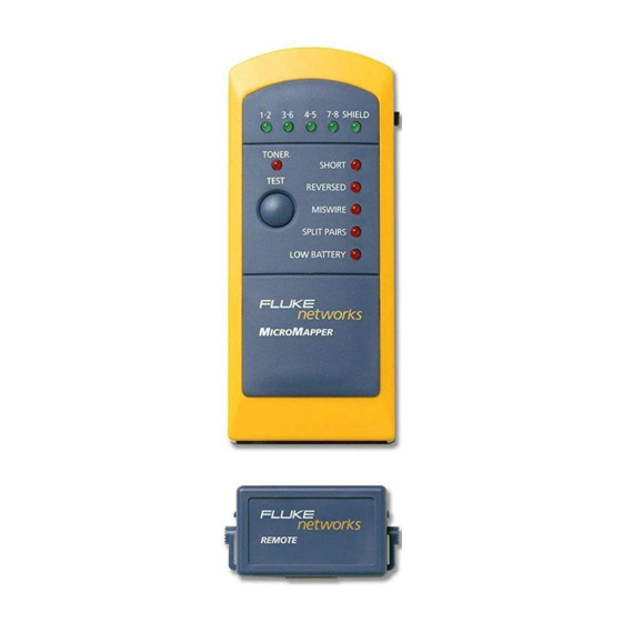
ICRO ROBE hidden in ceilings, walls, floors, and bundles. Contents MicroMapper Kit Content ............ 2 Features ................3 Battery ................3 High Voltage Protection ............4 MicroMapper's Toner Operation ......... 4 MicroMapper Tests ............. 5 Fault Status ................ - Page 5 Kit Content ICRO APPER - 1 M ICRO APPER - 1 M ICRO APPER REMOTE - This User Guide - Soft vinyl carrying case - Patch cord RJ45 Jack Pair and Shield Indicator LEDs Fault LEDs Toner LED TEST Button Battery Off- Cable-...
-
Page 6: Features
Features • Tests for wiring faults and detects opens, shorts, crossed, reversed, and split pairs. (Split pair fault detection requires a minimum cable length of 15.75" (40cm)) • Verifies shield integrity • M Remote Identifier enables one ICRO APPER person to test installed cabling •... -
Page 7: High Voltage Protection
High Voltage Protection Do not connect M to a live circuit as it may ICRO APPER damage the unit. Strong radio frequency fields may cause inaccurate readings. Do not open the unit or attempt to repair in case of malfunction. Please send it back to your distributor for repair or replacement. -
Page 8: Micromapper Tests
Tests ICRO APPER 1. Slide the switch on the right side to the Cable position to turn M ICRO APPER 2. Connect one end of the cable to be tested to the 's RJ45 jack. ICRO APPER 3. Connect the other end of the cable to the M ICRO Remote's RJ45 jack. -
Page 9: Fault Status
Fault Status SHORT OPEN REVERSED MIS-WIRE SPLIT PAIR ICRO APPER ENGLISH - 6... -
Page 10: Appendix A
Appendix A Connectors main unit: RJ 45 jack ICRO APPER Remote Identifier: RJ 45 jack Pairs tested 1 - 2, 3 - 6, 4 - 5, 7 - 8, and shield LED Display Horizontal: 5 green LEDs for pairs and shield display (1 - 2, 3 - 6, 4 - 5, 7 - 8, and SHIELD) Vertical: 6 red LEDs (TONER, SHORT, REVERSED, MISWIRE, SPLIT PAIRS, and LOW BATTERY) - Page 11 ICRO APPER ENGLISH - 8...
- Page 12 Contenu du kit MicroMapper ..........2 Fonctionnalités ..............3 Pile ..................3 Protection contre le risque de surtension ......4 Utilisation du toner de MicroMapper ........4 Tests MicroMapper ............. 5 Etat des anomalies ............. 7 Annexe A ................8...
-
Page 13: Contenu Du Kit Micromapper
Contenu du kit M ICRO APPER - 1 M ICRO APPER - 1 M ICRO APPER REMOTE - Le présent Manuel de l’utilisateur - Une mallette de transport souple en vinyle - Un câble de raccordement Fiche RJ-45 Voyants des paires et du blindage Témoins... -
Page 14: Fonctionnalités
Fonctionnalités • Recherche d’anomalies de câblage et détection de coupures, de courts-circuits, de paires croisées, de paires partagées et de paires inversées. (La détection de paires partagées nécessite une longueur de câble minimale de 40 cm). • Vérification de l’intégrité du blindage. •... -
Page 15: Protection Contre Le Risque De Surtension
Protection contre le risque de surtension Ne connectez pas M à un circuit sous tension ICRO APPER car cela risquerait d’endommager l’unité. La présence de champs haute fréquence peut nuire à la précision des mesures. N’ouvrez pas l’unité ou n’essayez pas de la réparer en cas de dysfonctionne- ment. -
Page 16: Tests Micromapper
mesure que l’on se rapproche du câble testé. 6. Orientez le commutateur situé sur la face droite de en position Off pour interrompre la ICRO APPER tonalité. (Mettez toujours l’unité hors tension pour empêcher l’épuisement de la pile.) ESTS ICRO APPER 1. - Page 17 à clignoter (rouge). Remarque : enfoncez le Remote Terminator sur le MicroMapper jusqu’à ce qu’il soit parfaitement en place. Le cas échéant, vous entendrez un clic. Cette configuration est très utile pour tester des câbles de raccordement.
-
Page 18: Etat Des Anomalies
Etat des anomalies SHORT (court-circuit) OPEN (coupure) REVERSED (paire inversée) MISWIRE (erreur de câblage) SPLIT PAIR (paire partagée) ICRO APPER FRANÇAIS - 7... - Page 19 Annexe A Connecteurs Unité principale M : Prise RJ-45 ICRO APPER Remote Identifier : Prise RJ-45 Paires testées 1 - 2, 3 - 6, 4 - 5, 7 - 8 et blindage Affichage à DEL Horizontalement : 5 voyants verts pour l’affichage des paires et du blindage (1 - 2, 3 - 6, 4 - 5, 7 - 8 et BLINDAGE) Verticalement : 6 voyants rouges (TONER, COUPURE, PAIRE INVERSEE, ERREUR DE CÂBLAGE, PAIRE PARTAGEE et BATTERIE...
- Page 20 Kabel zu verfolgen ICRO ROBE und um nach unter Putz in Decken, Wänden und Böden oder in Bündeln verlegten Kabeln zu suchen. Inhalt Inhalt des MicroMapper-Pakets2 Funktionen ................. 3 Batterie ................3 Überspannungsschutz ............4 MicroMapper-Signaltonbetrieb ........... 4 MicroMapper-Tests ............. 5 Fehlerstatus ...............
- Page 21 Inhalt des M -Pakets ICRO APPER - 1 M ICRO APPER - 1 M ICRO APPER REMOTE - Benutzerhandbuch - Tragetasche aus weichem Vinyl - Verbindungskabel RJ45-Stecker LED-Anzeigen für Adernpaare und geschirmte Kabel Fehleranzeigen LED-Anzeige für Signalton Taste TEST LED-Anzeige für niedrige Batterieladung Schalter mit...
-
Page 22: Funktionen
Funktionen • Prüft Kabel auf Verdrahtungsfehler und erkennt Unterbrechungen, Kurzschlüsse, überkreuzte, umgekehrte und vertauschte Paare. (Zur Erkennung von vertauschten Paaren muss das Kabel mindestens 40 cm lang sein.) • Prüft die Schirmung • Mit dem M -Remote-Prüfgerät kann die installierte ICRO APPER Verkabelung durch eine Person geprüft werden... -
Page 23: Überspannungsschutz
Überspannungsschutz Schließen Sie den M nicht an einen aktiven ICRO APPER Stromkreis an, da das Gerät dadurch beschädigt werden könnte. Starke Funkfrequenzbereiche können zu ungenauen Messergebnissen führen. Sie sollten das Gerät weder öffnen noch versuchen, es bei Fehlfunktio- nen zu reparieren. Bitte senden Sie das Gerät zu Reparatur- oder Austauschzwecken an Ihren Händler zurück. -
Page 24: Micromapper-Tests
. Der Signaltonempfang ist in der Nähe ICRO ROBE des jeweils zu prüfenden Kabels am stärksten. 6. Schieben Sie den Schalter auf der rechten Seite in die Position Off (Aus), um den Signal-ton zu unterbrechen. (Denken Sie daran, das Gerät auszuschalten, damit sich die Batterie nicht zu schnell entlädt.) - Tests... - Page 25 APPER ab, wobei alle LED-Anzeigen jeweils einzeln blinken. Bei Erkennung eines fehlerhaften Paars blinkt die entsprechende Fehler-Statusanzeige rot. Hinweis: Drücken Sie die Remote-Terminierung auf den MicroMapper, bis sie hörbar einrastet. Mit dieser Konfiguration können Sie Verbindungskabel problemlos prüfen. ICRO APPER...
-
Page 26: Fehlerstatus
Fehlerstatus SHORT (Kurzschluss) OPEN (Unterbrechung) REVERSED (Umgekehrt) MIS-WIRE (Falsche Verdrahtung) SPLIT PAIR (Vertauschtes Paar) ICRO APPER DEUTSCH - 7... -
Page 27: Anhang A
47 mm x 28 mm x 22 mm Gewicht mit Remote-Prüfgerät: 125 g ICRO APPER ACHTUNG: LASSEN SIE DAS GERÄT NICHT FALLEN ODER FEUCHT WERDEN. SETZEN SIE DEN MICROMAPPER NICHT EXTREMER FEUCHTIGKEIT ODER DIREKTER SONNENEINSTRAHLUNG AUS. ICRO APPER DEUTSCH - 8... - Page 28 Contenuto del kit MicroMapper ..........2 Funzionalità ................. 3 Batteria ................3 Protezione da alta tensione ..........4 Funzionamento del sintonizzatore di MicroMapper ....4 Test di MicroMapper ............5 Stati di errore ............... 7 Appendice A ................ 8 ICRO...
-
Page 29: Contenuto Del Kit Micromapper
Contenuto del kit MicroMapper - 1 M ICRO APPER - 1 M ICRO APPER REMOTE - Il presente Manuale dell’utente - Astuccio in morbido vinile - Cavo patch Jack RJ45 Indicatori LED per coppie e schermatura LED di errore sintonizzatore... -
Page 30: Funzionalità
Funzionalità • Verifica i difetti dei cavi in grado di rilevare aperture, cortocircuiti, coppie incrociate, invertite e divise (per individuare le coppie divise è necessaria una lunghezza minima di cavo di 40 cm (15,75”)). • Verifica l’integrità della schermatura • L’identificatore remoto di M consente a una sola ICRO APPER... -
Page 31: Protezione Da Alta Tensione
Protezione da alta tensione Non collegare M a un circuito attivo; l’unità ICRO APPER potrebbe venire danneggiata. Campi di radiofrequenze ad elevata intensità possono provocare errori di lettura. Non aprire l’unità o tentare di ripararla in caso di guasti. Inviare l’unità al locale distributore per la riparazione o la sostituzione. -
Page 32: Test Di Micromapper
6. Portare il commutatore sul lato destro nella posizione Off per interrompere il segnale acustico (ricordarsi di spegnere sempre l’unità, onde evitare che la batteria si scarichi). Test di M ICRO APPER 1. Portare il commutatore sul lato destro nella posizione Cable per accendere M ICRO APPER... - Page 33 LED separatamente. Se viene rilevata una coppia difettosa, il corrispon- dente stato di errore viene segnalato dal lampeggiamento rosso. Nota: Spingere il terminatore remoto su MicroMapper facendolo scattare in posizione. Questa configurazio- ne permette di collaudare comodamente i cavi patch. ICRO...
-
Page 34: Stati Di Errore
Stati di errore SHORT CORTOCIRCUITO OPEN APERTURA REVERSED COPPIA INVERTITA MIS-WIRE FILO ERRATO SPLIT PAIR COPPIA DIVISA ICRO APPER ITALIANO - 7... -
Page 35: Appendice A
Appendice A Connettori Unità principale M : Jack RJ 45 ICRO APPER Identificatore remoto: Jack RJ 45 Coppie testate 1 - 2, 3 - 6, 4 - 5, 7 - 8 e schermatura Display LED Orizzontali: 5 LED verdi per display di coppie e schermatura (1 - 2, 3 - 6, 4 - 5, 7 - 8 e SCHERMATURA) Verticali: 6 LED rossi (SINTONIZZATORE, CORTOCIRCUITO, COPPIE INVERTITE, FILO ERRATO, COPPIE DIVISE e BATTERIA... - Page 36 ........... 2 ICRO APPER Características ..............3 Battería ................3 Protección contra sobretensión .......... 4 Funcionamiento del emisor de tonos de MicroMapper ..4 Pruebas con MicroMapper ..........5 Estados de fallo ..............7 Apéndice A ................. 8 ICRO APPER...
- Page 37 Contenido del kit M ICRO APPER - 1 M ICRO APPER - 1 M ICRO APPER REMOTE - Este manual del usuario - Un maletín de vinilo flexible - Cable de pruebas Jack RJ45 Indicadores LED de blindaje y de par Indicadores luminosos (LED) de...
-
Page 38: Características
Características • Comprueba los fallos de los cables y detecta los pares abiertos, en cortocircuito, cruzados, invertidos y separados. (Para detectar un par separado se necesita un cable de una longitud mínima de15,75 pulgadas (40cm)) • Comprueba la integridad del blindaje •... -
Page 39: Protección Contra Sobretensión
Protección contra sobretensión No conecte M a un circuito en funciona- ICRO APPER miento. Podría dañar el dispositivo. Los campos de frecuencia de radio de gran intensidad podrían dar lugar a lecturas poco precisas. No abra el aparato ni intente repararlo si no funcionara correctamente. Devuélvalo a su distribuidor para su reparación o reemplazo. -
Page 40: Pruebas Con Micromapper
intensa cerca del cable que se está comprobando. 6. Desplace el conmutador situado a la derecha hasta la posición Off para suspender el tono. (Mantenga apagado el dispositivo para evitar que se agote la pila). Pruebas con M ICRO APPER 1. - Page 41 LED. Si detectara un par con fallo, el estado de fallo correspondiente parpadearía en rojo. Nota: Pulse el terminador remoto de MicroMapper hasta que encaje. Con esta configuración es posible comprobar cables de pruebas con comodidad.
-
Page 42: Estados De Fallo
Estados de fallo SHORT CORTOCIRCUITO OPEN ABIERTO REVERSED INVERTIDO MIS-WIRE MAL CONECTADO SPLIT PAIR SEPARADO ICRO APPER ESPAÑOL - 7... -
Page 43: Apéndice A
Apéndice A Conectores: Dispositivo principal de M : Jack RJ 45 ICRO APPER Identificador remoto: Jack RJ 45 Pares comprobados 1 - 2, 3 - 6, 4 - 5, 7 - 8 y blindaje Visualización de LED Horizontal: Visualización de 5 indicadores LED para pares y blindaje (1 - 2, 3 - 6, 4 - 5, 7 - 8 y BLINDAJE) Vertical: 6 indicadores LED rojos (EMISOR DE TONOS, PARES CON CORTOCIRCUITOS, INVERTIDOS, MAL CONECTADOS y SEPARA-... - Page 44 Conteúdo do Kit MicroMapper ..........2 Características ..............3 Bateria ................. 3 Proteção Contra Alta Tensão ..........4 Operação do MicroMapper com sinal acústico ....4 Testes do MicroMapper ............5 Estado de Falha ..............6 Apêndice A ................7...
-
Page 45: Conteúdo Do Kit Micromapper
Conteúdo do Kit M ICRO APPER - 1 M ICRO APPER - 1 M ICRO APPER REMOTE - Este Manual do Usuário - Embalagem de transporte em vinil flexível - Cabo de conexão Conector RJ45 Indicadores luminosos de Indicadores Par e Luminosos Blindagem de Falha... -
Page 46: Características
Características • Testa falhas de cabeamento e detecta pares abertos, em curto, cruzados, invertidos e rompidos. (A detecção de pares rompidos exige um comprimento de cabo mínimo de 15,75" (40cm)) • Verifica a integridade da blindagem • O Identificador Remoto do M permite que uma ICRO APPER... -
Page 47: Proteção Contra Alta Tensão
Proteção Contra Alta Tensão Não conecte o M a um circuito ‘vivo’, pois ele ICRO APPER pode danificar a unidade. Campos fortes de radiofreqüência podem gerar leituras imprecisas. Não abra a unidade nem tente repará-la em caso de defeito. Devolva-a ao seu distribuidor para reparos ou substitui- ção. - Page 48 Se for detectado um par defeituoso, o estado de falha correspondente piscará em vermelho. Nota: Empurre o Terminador Remoto para o MicroMapper até que ele se encaixe na posição. Essa configuração permite que você teste cabos de conexão de forma prática.
-
Page 49: Estado De Falha
Estado de Falha SHORT CURTO OPEN ABERTO REVERSED INVERTIDO MIS-WIRE ERRO DE CABEAMENTO SPLIT PAIR PAR ROMPIDO ICRO APPER PORTUGUÊS - 6... -
Page 50: Apêndice A
Apêndice A Conectores – Unidade Principal: conector RJ 45 ICRO APPER Identificador Remoto: conector RJ 45 Pares testados 1 - 2, 3 - 6, 4 - 5, 7 - 8, e blindagem Indicadores Luminosos Horizontal: 5 LEDs verdes para exibição de pares e blindagem (1 - 2, 3 - 6, 4 - 5, 7 - 8, e BLINDAGEM) Vertical: 6 LEDs vermelhos (GERADOR DE SINAL ACÚSTICO, CURTO, INVERTIDO, ERRO DE... - Page 51 ICRO APPER PORTUGUÊS - 8...
- Page 52 LIMITED WARRANTY & LIMITATION OF LIABILITY Each Fluke Networks product is warranted to be free from defects in material and workmanship under normal use and service. The warranty period is one year and begins on the date of purchase. Parts, accessories, product repairs and services are warranted for 90 days.
- Page 53 6-01 781-665-0780 FAX Registration Registering your product with Fluke Networks gives you access to valuable information on product updates, troubleshooting tips, and other support services. To register, fill out and return the postage- paid card provided, or fill out the online registration form on the Fluke Networks website.
- Page 54 M I C R O T O O L S...