Table des Matières

Publicité

Les langues disponibles

Les langues disponibles

Liens rapides

®
PowerScan
RF
Handheld Bar Code Scanner
Handstrichcodeleser
Douchette Laser
Lettore portatile di codici a barre
SR/HD/LR/XLR
User's Guide
Benutzerhandbuch
Guide de L'utilisateur
Manuale d'Istruzioni

Publicité

Table des Matières
loading

Sommaire des Matières pour Datalogic PowerScan RF SR

  • Page 1 ® PowerScan Handheld Bar Code Scanner Handstrichcodeleser Douchette Laser Lettore portatile di codici a barre SR/HD/LR/XLR User’s Guide Benutzerhandbuch Guide de L’utilisateur Manuale d’Istruzioni...
  • Page 2 Datalogic reserves the right to change any specification at any time without prior notice. Datalogic is a registered trademark of Datalogic S.p.A. and the Datalogic logo is a trademark of Datalogic S.p.A. all licensed to Datalogic Scanning, Inc. All other trademarks and trade names referred to herein are property of their respective owners.
  • Page 3: End User License Agreement

    Agreement. If you do not intend to be bound to the terms of this Agreement, Data- logic is not willing to license the Software to you, you may not use the Datalogic Product or the Software, and you must contact the party from whom you acquired the Datalogic Product for instructions.
  • Page 4 Software clause at DFARS 252.227-7013(c)(1)(ii), whichever is applicable. If End User is using the Datalogic Product outside of the United States, End User must comply with the applicable local laws of the country in which the Datalogic Product is used, with U.S. export control laws, and with the English language version of this Agreement. The provisions of the “United Nations Convention on International Sale of Goods”...
  • Page 5: Limitations Of Liability

    Risk of Loss Customer shall bear risk of loss or damage for product in transit to Datalogic. Datalogic shall assume risk of loss or damage for product in Datalogic’s posses- sion or product being returned to Customer by Datalogic, except such loss or damage as may be caused by the negligence of Customer, its agents or employ- ees.
  • Page 6 NOTES User’s Guide...
  • Page 7 MASTER CONTENTS Table of Contents ................1 Deutsches Inhaltsverzeichnis ............29 Français Sommaire ..............59 Italiano Indice ................87 User’s Guide...
  • Page 8 ® PowerScan RF Scanner...
  • Page 9: Table Des Matières

    TABLE OF CONTENTS Unpack and Inspect Your Scanner ................1 References ........................1 Quick Start Instructions ....................1 Installing the Battery ....................2 Verifying Scanner Operation ...................3 Power Supply ......................3 Connecting the Base Station to the Host Terminal ..........3 Linking the Scanner to a Base Station ..............5 Verifying Scanner-to-Base Station Communications ..........7 Using the PowerScan RF System .................8 Battery Charging and Maintenance ................8...
  • Page 10 ® PowerScan RF Scanner...
  • Page 11: Unpack And Inspect Your Scanner

    Unpack and Inspect Your Scanner After unpacking your new scanner, check the contents of the shipping carton to ensure all the items you ordered are included: ® • PowerScan RF handheld scanner • Battery Pack(s) • User’s Guide (this manual) •...
  • Page 12: Installing The Battery

    Installing the Battery To assure maximum usage, batteries should always be fully charged before their initial use. (See “Bat- tery Charging and Maintenance” on page 10.) NOTE Orient the battery as shown in Figure 1, then push it into the scanner until it snaps in place.
  • Page 13: Verifying Scanner Operation

    Verifying Once a charged battery has been installed in the scanner, scan the sam- ple bar codes in the back of this manual that correspond to the symbol- Scanner ogies your scanner is programmed to read. If unsure how to do this, Operation see the section on How to Scan in this manual.
  • Page 14 Figure 2. Connecting/Disconnecting the Interface (I/F) Cable Consult your Host Terminal manual to determine the required communication parameters for the Host Terminal (e.g., baud rate, parity, etc.) and, if necessary, modify the programmed parameters to be compatible with those requirements. Scanner and Base Station programming is performed using one of the following: - Configurator Express™...
  • Page 15: Linking The Scanner To A Base Station

    The Base Station’s POWER LED should be illuminated when the unit is properly connected to power. Figure 3. Connecting Power to the Base Station Apply power to the Host Terminal. Verify communication with the Host Terminal by aiming the linked scanner at a sample bar code from the back pages of this manual, and pulling the trigger (see How to Scan for tips about scanning bar codes).
  • Page 16 The existing Base Station system configuration can be automatically downloaded to the scanner. This automatic download feature is config- urable and can be disabled. See the Systems Manual for more informa- tion about this feature. If downloading occurs, a slight delay with link verification announcement will occur.
  • Page 17: Verifying Scanner-To-Base Station Communications

    Verifying Point the linked scanner at a sample bar code from the back pages of this manual, and pull the trigger (see How to Scan for tips on scanning Scanner-to- bar codes). Watch the TX/RX (transmit/receive) indicator LED on the Base Station Base Station and/or scanner green LED while scanning the bar code.
  • Page 18: Using The Powerscan Rf System

    Using the PowerScan RF System This section covers the following topics: • Battery Charging and Maintenance • How to Scan • LED and Beeper Indications Battery Charging and Maintenance When the scanner is in use, a low battery condition is indicated by a repeated two-flash signal from the scanner’s green LED every time the trigger is pulled before the laser is enabled.
  • Page 19 Rapid flashing indicates that charging is taking place. Rapid charging occurs when the battery temperature is between 10°C (50°F) and 46°C (115°F), and/or voltage of the battery is between 2.0 and 3.2V. Charge time is less than 4.2 hours. Rapid charge ends with the battery at approximately 90 to 95% capacity.
  • Page 20: Disposing Of Batteries

    Disposing of There presently are no US, North America or World disposal require- ments for NiMH batteries, so when they won't hold a charge anymore, Batteries the batteries can be disposed of, preferably through a recycling center. Four Station If you have a Four Station Charger, batteries are inserted for charging as shown in Figure 5.
  • Page 21: How To Scan

    How to Scan Figure 6 illustrates some tips to help get the best scanning results: The scanner must be pointed at a slight angle to the bar code. Do not hold the scanner perpendicular to the bar code. The laser beam must cross the entire bar code. The scanner cannot correctly read if the entire bar code is not scanned.
  • Page 22: Depth Of Field

    Depth of Field There are currently four different range models for the scanner. Depending upon the model type of your scanner, you’ll need to hold the unit at a given distance from the bar code to achieve optimum scan- ning results. The following diagrams provide depth of field informa- tion for each of the models when scanning grade A, Code 39 bar codes: Standard Range (SR), High Density (HD), Long Range (LR) and Extra Long Range (XLR).
  • Page 23 See the section titled, Definition of a "mil" for more information about reading this chart. Measurements are based on HD models set with the standard 28° scan width (as opposed to the Half Angle setting of 14°). Reference the Programming Manual for more information about the Half Angle feature.
  • Page 24 See the section titled, Definition of a "mil" for more information about reading this chart. Measurements are based on LR models set with the a 14° scan width (as opposed to the alternate Full Angle set- ting of 28°). Reference the Programming Manual for more information about the Half Angle feature.
  • Page 25 See the section titled, Definition of a "mil" for more information about reading this chart. Measurements are based on XLR models set with a 10° scan angle width. NOTE Specifications are subject to change without notice. Figure 10. Depth of Field (XLR) Depth of Field Paper Labels (XLR decoded model, Code 39) 15 mil...
  • Page 26: Led And Beeper Indications

    LED and Beeper Indications The Base Station LED indicators and the scanner’s LEDs and beeper are used to announce system status and perform other useful signals. The tables below list the default function of each of the various indica- tors. Some LED and beeper indications can be disabled or modified via scanner programming.
  • Page 27 Table 2. Scanner YELLOW LED Functions DURATION COMMENT INDICATION On Steady Laser on indica- The yellow LED illuminates tion whenever the laser is on. Table 3. Scanner BEEPER Functions SPEAKER DURATION COMMENT INDICATION Indicates a bar code was Six beeps consisting of 20 ms Scanner Not read before the scanner on, 20 ms off...
  • Page 28 SPEAKER DURATION COMMENT INDICATION High, then low, then high, then low. Transmission Indicates unsuccessful Error Beep transmission to the host. Low, then medium, then high. Indicates a scanner has Link Beep been successfully linked to a base station. High, then medium, then low. Indicates a scanner has Unlink Beep been successfully unlinked...
  • Page 29: Active Symbologies

    DURATION COMMENT INDICATION When a scanner is nested Continuous flashing in the station, this indicates its battery is being quick charged. When a scanner is nested in the station, this indicates Lit Constantly Charge its battery is at or near full (Battery) charge.
  • Page 30: Enhanced Scanning For Hard-To-Read Bar Codes

    Enhanced Decoded scanners can be programmed to decode extremely poor qual- ity bar codes by activating advanced Quadralogic II™ Decoding. To Scanning for select this feature, see the Programming Guide. Hard-to-Read Bar Codes Scanner programming can also be performed using your PC and the Configurator Express™...
  • Page 31: Laser Cautions

    The optics system CAUTION is a factory only repair item. ® The PowerScan RF scanner is required to be used in conjunction with the Datalogic Base Station, Model: PowerScan RF Base Station. NOTE User’s Guide...
  • Page 32: Radio Frequency Interference

    Radio Frequency Interference This device complies with Part 15 of the FCC Rules. Operation is sub- ject to the following two conditions: This device may not cause harmful interference, and This device must accept any interference received, including interference that may cause undesired operation. This Class A digital apparatus complies with Canadian ICES-003.
  • Page 33: Maintenance

    Maintenance The scan window will require occasional cleaning to remove smudges, dust and other debris. To ensure optimal performance, clean the Scan Window using a soft cloth or lens tissue dampened with isopropyl alcohol (or equivalent). See Figure 12. The scanner body can also be cleaned using this method.
  • Page 34: Troubleshooting

    Troubleshooting Troubleshoot your RF scanning system by performing the following checks: For the RF system, ensure that... • the battery is charged. See “Battery Charging and Mainte- nance” on page 10. • the battery is properly installed. See “Installing the Battery” on page 4.
  • Page 35: Sample Bar Codes

    Sample Bar Codes Use these test bar codes to check the scanner’s ability to read the vari- ous symbologies represented. Code 128 C o d e 1 2 8 T e s Code 39 Interleaved 2 of 5 0 1 2 3 4 5 6 7 8 9 Standard 2 of 5 1 2 3 4 5 6 7 8 9 0 Codabar...
  • Page 36 MSI/Plessey 14476925 UPC-A 0 0 1 1 2 2 3 3 4 4 UPC-A with 2 digit Add-on 6 0 9 9 2 0 1 1 1 8 6 9 0 0 0 UPC-A with 5 digit Add-on 0 8 0 2 9 5 1 0 4 1 UPC-E 9 9 8 8 7 5 EAN-8...
  • Page 37 DEUTSCHES INHALTSVERZEICHNIS Auspacken und Überprüfen Ihres Scanners ..............31 Referenzen ........................31 Anweisungen für den Schnellstart ................31 Einlegen der Batterie ....................32 Überprüfen des Scannerbetriebes ................33 Netzteil ........................33 Anschließen der Basisstation an das Hauptterminal ..........33 Verbinden des Scanners mit der Basisstation ............35 Prüfen der Verbindung Scanner-an-Basisstation ..........37 Anwenden des PowerScan RF-Systems ..............38 Batterieaufladung und Wartung ................38 Tipps zur Verlängerung der Batteriehaltbarkeit ............39...
  • Page 38 ändern, und er gewährleistet, dass alle Hinweise auf jeglichen Vervielfältigungen der Dokumente erscheinen. Wenn zukünftig Überarbeitungen dieses Handbuches herausgegeben werden, können Sie die gedruckten Versionen über die Datalogic Kun- denverwaltung erhalten. Die elektronischen Versionen können entweder von der Datalogic-Webseite (www.scanning.datalogic.com) heruntergeladen werden oder Ihnen auf einem entsprechenden Medium geschickt werden.
  • Page 39: Auspacken Und Überprüfen Ihres Scanners

    Auspacken und Überprüfen Ihres Scanners Nachdem Sie Ihren neuen Scanner ausgepackt haben, überprüfen Sie den Inhalt des Lieferkartons, ob auch alle von Ihnen bestellten Teile geliefert wurden: ® • PowerScan RF Handscanner • Batterie/n • Benutzerhandbuch (dieses Handbuch) • zusätzliches Zubehör, das Sie bestellt haben. (Der Scanner kann mit oder ohne Zubehör-Kit bestellt werden) Wenn Ihr Paket falsche Teile enthält oder wenn Teile fehlen, wenden Sie sich bitte an Ihre Verkaufsstelle.
  • Page 40: Einlegen Der Batterie

    Einlegen der Batterie Für eine maximale Lebensdauer sollten die Batte- rien vor der ersten Anwendung immer vollständig aufgeladen sein. (Siehe “Batterieaufladung und Wartung” auf Seite 38). Hinweis Richten Sie die Batterie wie in Abbildung 1 gezeigt aus und drücken Sie die Batterie dann so weit in den Scanner, bis sie einrastet. Die Batte- rie wird herausgenommen, indem Sie auf die Lösetasten an beiden Seiten des Batterieteils drücken und die Batterie gerade aus dem Scan- ner herausziehen.
  • Page 41: Überprüfen Des Scannerbetriebes

    Überprüfen des Sobald die aufgeladene Batterie in den Scanner eingelegt wurde, scan- nen Sie jene Muster-Barcodes auf den letzten Seiten dieses Hand- Scannerbetriebes buches, die der Symbolik entsprechen, für die Ihr Scanner programmiert ist. Wenn Sie sich über die Vorgehensweise unsicher sind, lesen Sie den Abschnitt dieses Handbuches "Wie wird gescannt".
  • Page 42 Abbildung 2 Anschließen/Trennen des Schnittstellen-(I/F)Kabels Lesen Sie im Hauptterminal-Handbuch die erforderlichen Kommunikationsparameter für das Hauptterminal nach (z.B. Baud-Rate, Parität, usw.) und ändern Sie falls erforderlich die programmierten Parameter, damit diese mit den Anforderun- gen übereinstimmen. Die Programmierung des Scanners und der Basisstation wird mit einem der folgenden Mittel aus- geführt: Configurator Express™...
  • Page 43: Verbinden Des Scanners Mit Der Basisstation

    Schließen Sie das Stromkabel des AC-Adapters an die Basissta- tion an und stecken Sie den AC/DC-Adapter in die Wand- steckdose (siehe Abbildung 3). Die Strom-LED der Basisstation leuchtet, wenn die Einheit korrekt an das Stromnetz angeschlo- ssen ist. Abbildung 3: Die Basisstation mit dem Stromnetz verbinden Schalten Sie den Strom für das Hauptterminal an.
  • Page 44 Die bestehende Systemkonfiguration der Basisstation kann automa- tisch auf den Scanner übertragen werden. Dieses Merkmal der automa- tischen Übertragung kann konfiguriert und abgestellt werden. Für weitere Informationen zu diesem Merkmal siehe Systemhandbuch. Bei einer Übertragung tritt eine leichte Verzögerung der Anzeige der Verbindungsüberprüfung auf.
  • Page 45: Prüfen Der Verbindung Scanner-An-Basisstation

    Prüfen der Halten Sie den verbundenen Scanner auf einen Muster-Barcode der letzten Seiten dieses Handbuches und ziehen Sie den Auslöser (für Verbindung Tipps zum Scannen von Barcodes siehe "Wie wird gescannt"). Während Scanner-an- Sie den Barcode scannen, beobachten Sie die LED-Anzeige TX/RX Basisstation (übertragen/empfangen) auf der Basisstation und/oder die grüne LED am Scanner.
  • Page 46: Anwenden Des Powerscan Rf-Systems

    Anwenden des PowerScan RF-Systems Dieser Abschnitt behandelt die folgenden Punkte: • Batterieaufladung und Wartung • Wie wird gescannt • LED- und Signal-Anzeigen Batterieaufladung und Wartung Wenn der Scanner in Betrieb ist, wird über ein wied- erholtes zweimaliges Blinksignal der grünen LED des Scanners jedes Mal ein niedriger Batterie- zustand angezeigt, wenn der Auslöser vor der Aktivierung des Lasers gezogen wird.
  • Page 47: Entsorgung Der Batterien

    Ein schnelles Blinken zeigt an, dass das Aufladen stattfindet. Ein schnelles Aufladen erfolgt, wenn die Batterietemperatur zwischen 10°C (50°F) und 46°C (115°F) liegt, und/oder die Batteriespannung zwischen 2,0 und 3,2 V liegt. Die Ladezeit beträgt weniger als 4,2 Stunden. Die schnelle Aufladung wird bei einer 90 bis 95%-igen Batte- rieleistung abgeschlossen.
  • Page 48: Vier-Stationen-Ladegerät

    Vier-Stationen- Wenn Sie über ein Vier-Stationen-Ladegerät verfügen, dann werden die Batterien zur Aufladung wie in Abbildung 5 gezeigt eingelegt. Eine Ladegerät 90%-ige Aufladung wird in nur zwei Stunden erzielt, wenn dieses zusätzliche Zubehör verwendet wird - dass entspricht der Hälfte der Zeit, die für eine Aufladung über die Basisstation erforderlich ist.
  • Page 49: Wie Wird Gescannt

    Wie wird gescannt Abbildung 6 zeigt einige Tipps, wie Sie die besten Ergebnisse beim Scannen erzielen können: Der Scanner muss mit einem kleinen Winkel zum Barcode gehalten werden. Der Laserstrahl muss den gesamten Barcode überqueren. Der Scanner kann nicht korrekt einlesen, wenn nicht der gesamte Barcode gescannt wird.
  • Page 50: Feldtiefe

    Feldtiefe Derzeit gibt es für den Scanner vier verschiedene Reichweitenmodelle. Abhängig vom Modelltyp Ihres Scanners, müssen Sie die Einheit mit einem bestimmten Abstand vom Barcode halten, um ein optimales Ergebnis beim Scannen zu erzielen. Die folgenden Diagramme geben die Feldtiefen für jedes der Modelle an, wenn Barcodes von Grad A, Code 39 gescannt werden: Standardreichweite (SR), hohe Dichte (HD), große Reichweite (LR) und extra große Reichweite (XLR).
  • Page 51 Für weitere Informationen zu diesen Diagrammen siehe Abschnitt "Definition eines "Mil"". Die Mes- sungen basieren auf den Einstellungen der HD- Modelle mit der standardmäßigen 28° Scanbreite (im Gegensatz zu der Halbwinkeleinstellung von 14°). Für weitere Informationen über Halb- winkelmerkmale siehe "Programmierhandbuch". Hinweis Diese Spezifikationen können Änderungen ohne vorige Mitteilung unterliegen.
  • Page 52 Für weitere Informationen zu diesen Diagrammen siehe Abschnitt "Definition eines "Mil"". Die Mes- sungen basieren auf den Einstellungen der LR- Modelle mit der standardmäßigen 14° Scanbreite (im Gegensatz zu der alternativen Vollwinkeleinstel- lung von 28°). Für weitere Informationen über Halb- winkelmerkmale siehe "Programmierhandbuch".
  • Page 53 Für weitere Informationen zu diesen Diagrammen siehe Abschnitt "Definition eines "Mil"". Die Mes- sungen basieren auf den Einstellungen der XLR- Modelle mit der 10° Scanwinkelbreite. Diese Spezifikationen können Änderungen ohne Hinweis vorige Mitteilung unterliegen. Abbildung 10: Feldtiefe (XLR) Feldtiefe Papierlabel (Modell XLR, Code 39) 15 mil 20 mil 40 mil...
  • Page 54: Led- Und Signal-Anzeigen

    LED- und Signal-Anzeigen Die LED-Anzeigen der Basisstation und die LEDs des Scanners sowie die Pieptöne geben den Systemstatus an und führen weitere nützliche Signale durch. Die folgende Tabelle listet die Standardvorgaben für jede der verschiedenen Anzeigen auf. Einige LEDs und Signal-Anzeigen können abgest- ellt oder über die Scanner-Programmierung geändert werden.
  • Page 55 Tabelle 2: Gelbe LED-Funktionen des Scanners LED- Dauer Kommentar Anzeige Die gelbe LED leuchtet an, stetig Anzeige Laser immer dann, wenn der Laser eingeschaltet ist. Tabelle 3: Signal-Funktionen des Scanners Anzeige Dauer Kommentar Lautsprecher Zeigt an, dass ein Barcode sechs Pieptöne bestehend Scanner im gelesen wurde, bevor der aus 20 ms an, 20 ms aus...
  • Page 56 Anzeige Dauer Kommentar Lautsprecher Zeigt an, dass eine 100 ms an (kurz) erfolgreiche Barcode-Über- tragung zum Haupttermi- Signal Bestäti- nal (konfigurierbar), ein 250 ms an (mittel) gung der Basiss- erfolgreicher Kanalwechsel tation oder eine erfolgreiche 500 ms an (lang) Übertragung einer neuen Konfiguration zum Haupt- terminal stattgefunden hat.
  • Page 57 LED- Dauer Kommentar Anzeige leuchtet über eine variable Zeigt eine bestehende Kommunikation zur oder Zeitdauer von der Basisstation an. fortlaufendes schnelles Blinken bei angelegter Netzs- Zeigt ein beschädigtes TX/RX pannung Empfangsgerät an. (Übertragen/ Empfangen) Verschieden. Besteht aus Ermöglicht es dem Service- einem langen Blinken gefolgt techniker, einen Fehler der von vielen kurzen Blinken...
  • Page 58: Aktive Symboliken

    Aktive Die aktiven (aktivierten) Barcodesymboliken der werksseitigen Stan- dardvorgaben sind: Symboliken • Code 39 (C39) • Code 128 (C128) • Überlappung 2 von 5 (I 2 von 5) Ihr Scanner sollte mit diesen werksseitigen Einstellungen der Stan- dardvorgaben vorprogrammiert sein, sofern ..
  • Page 59 Abbildung 11: Scanner-Etikettierung und Nomenklatur MODEL: CLASS No. 073200496 SERIAL No. XXXXX MFG. DATE: FREQ: LASER RADIATION-DO NOT STARE INTO BEAM 1mw - 650-685nm CLASS 2 LASER PRODUCT Complies with 21CFR 1040 and part 15 of Based on 100 sec., EN60825-1/A11:1996 FCC Rules.
  • Page 60: Warnhinweise Für Laseranwendung

    Warnhinweise für Laseranwendung Der PowerScan RF Barcodescanner ist in den USA zertifiziert und entspricht den Anforderungen von DHHS/CDRH 21 CFR Unterkapi- tel J für Laserprodukte der Klasse II (SR und LR) und Klasse IIIa (XLR). Produkte der Klasse II und IIIa sind nicht als gefährlich eingestuft. Der Scanner enthält eine Visible Laser Diode (VLD) mit einer Wellenlänge von 650-670 Nanometer und ist so konstruiert, dass bei normalem Betrieb, normaler Anwenderwartung oder bei den vorgeschriebenen...
  • Page 61: Hochfrequente Störungen

    Hochfrequente Störungen Dieses Gerät erfüllt Teil 15 der FCC-Bestimmungen. Der Betrieb unter- liegt den folgenden zwei Bedingungen: Dieses Gerät verursacht keine schädlichen Störungen. Dieses Gerät akzeptiert alle empfangenen Störungen, ein- schließlich Störungen, die einen nicht gewünschten Betrieb verursachen. Dieser digitale Apparat der Klasse A erfüllt Canadian ICES-003. Cet appareil numérique de la classe A est conforme à...
  • Page 62: Wartung

    Wartung Das Scanfenster muss gelegentlich gereinigt werden, um Schmutz, Staub und andere Rückstände zu beseitigen. Für eine optimale Leis- tung reinigen Sie das Scanfenster mit einem weichen Tuch oder einem Linsentuch, das mit Isopropylalkohol (oder Ähnliches) angefeuchtet ist. Siehe Abbildung 12. Der Scannerkörper kann ebenso mit dieser Methode gereinigt werden.
  • Page 63: Fehlersuche

    Fehlersuche Sie führen die Fehlersuche für Ihr RF-Scanningsystem nach den fol- genden Checks durch: Für das RF-System vergewissern Sie sich, dass • die Batterie geladen ist. Siehe “Batterieaufladung und War- tung” auf Seite 38. • die Batterie korrekt eingelegt ist. Siehe “Einlegen der Batterie” auf Seite 32.
  • Page 64 dass das Problem bei den Barcodes liegt, prüfen Sie, ob der Scanner einen Muster-Barcode von den folgenden Seiten lesen kann. • die programmierbare Einstellung für fortgeschrittene Quadral- ogic II™-Dekodierung optimal für Ihr System eingestellt ist. (Siehe “Erweitertes Scannen für schlecht lesbare Barcodes” auf Seite 50.) ®...
  • Page 65: Muster-Barcodes

    Muster-Barcodes Verwenden Sie diese Test-Barcodes, um die Fähigkeit des Scanners zum Einlesen der verschiedenen Symboliken zu prüfen. Code 128 C o d e 1 2 8 T e s Code 39 Überlappend 2 von 5 0 1 2 3 4 5 6 7 8 9 Standard 2 von 5 1 2 3 4 5 6 7 8 9 0 Codabar...
  • Page 66 MSI/Plessey 14476925 UPC-A 0 0 1 1 2 2 3 3 4 4 UPC-A mit 2 Zeichen Add-on 6 0 9 9 2 0 1 1 1 8 6 9 0 0 0 UPC-A mit 5 Zeichen Add-on 0 8 0 2 9 5 1 0 4 1 UPC-E 9 9 8 8 7 5 EAN-8...
  • Page 67 FRANÇAIS SOMMAIRE Déballage et inspection de votre scanner ..............61 References ........................61 Instructions Pour le Demarrage Rapide ..............61 Installation de la Batterie ..................62 Vérification du scanner ..................63 Connexion de la Base au Terminal Hote ..............63 Liaison du Scanner a la Base ................65 Verification de la Communication Entre la Base et le Scanner ......66 Utilisation du PowerScan RF ..................67 Chargement et maintenance de la batterie ............67...
  • Page 68 Ph: [33].01.64.86.71.00 Fax: [33].01.64 46.72.44 Datalogic, le logo Datalogic, Quadralogic et Powerscan sont des marques déposées de Datalogic Scanning, Inc. . Toute autre marque ou nom déposé mentionnés ci-après sont les biens de leur propriété respective. Tous les droits sont réservés. Le contenu, même partiel de cette bro- chure ou des procédures décrites ci-après ne peuvent faire l'objet de...
  • Page 69: Déballage Et Inspection De Votre Scanner

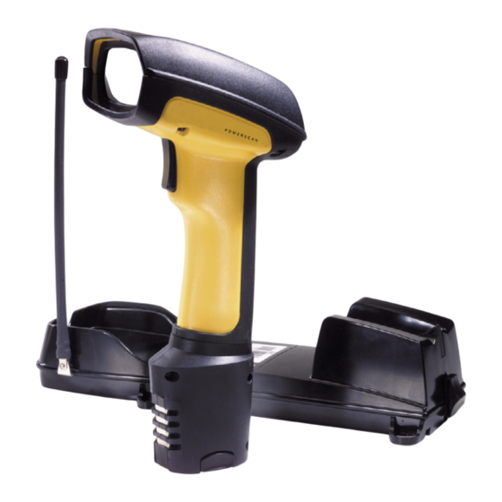
    Déballage et inspection de votre scanner Après avoir ôté de son emballage votre lecteur, bien vérifier le contenu du carton pour s'assurer qu'aucun article commandé ne manque, à savoir : • Le scanner PowerScan RF ; • Le(s) pack(s) batteries ; •...
  • Page 70: Installation De La Batterie

    Installation de la Batterie Pour assurer un maximum d'utilisations, les batter- ies doivent toujours être chargées au maximum avant la première utilisation. (Voir “Chargement et maintenance de la batterie” en page 67.) NOTE Orientez la batterie selon la Schéma 1, puis poussez la dans le scanner jusqu'à...
  • Page 71: Vérification Du Scanner

    Vérification du Une fois que la batterie chargée a été installée dans le scanner, scannez les exemplaires de codes à barres à la fin de ce manuel qui correspon- scanner dent aux symbologies pour lesquelles votre scanner est programmé. Si vous n'êtes pas sûre de savoir comment le faire, voyez la section "...
  • Page 72 Schéma 2. Conection et Deconnection du Câble (I/F) Consultez votre manuel de terminal HOTE afin de déterminer les paramètres de communication requis pour le Terminal HOTE (e.g., débit, parité, etc…) et, si nécessaire, modifier les paramètres de programmation afin d'être compatible avec ces exigences.
  • Page 73: Liaison Du Scanner A La Base

    LED de la base devrait être allumée quand l'unité est branchée à la prise. Schéma 3. Connexion de la Base a L'alimentation Branchez l'alimentation du terminal HOTE. Vérifiez la communication avec le terminal HOTE en pointant un exemplaire de code à barres des dernières pages du présent manuel, et appuyer sur la gâchette.
  • Page 74 La configuration de la base peut être automatiquement chargée sur le scanner. Le téléchargement automatique est configurable et peut être désactivé. Voir " Le Manuel du Système " pour plus d'informations à ce sujet. Si un téléchargement survient, un petit délai avec l'annonce du lien de vérification aura lieu.
  • Page 75: Utilisation Du Powerscan Rf

    Utilisation du PowerScan RF Cette section couvre les sujets suivants : • Chargement et maintenance de la batterie ; • Comment Scanner ; • Indicateurs : LED et Beeper. Chargement et maintenance de la batterie Lorsque le scanner est en marche, un état de batte- rie faible est indiqué...
  • Page 76: Astuces Pour Augmenter La Duree De Vie De La Batterie

    Des clignotements rapides indiquent que le chargement est en cours. Un chargement rapide se réalise lorsque la température de la batterie est entre 10°c et 46°c, et/ou la tension de la batterie est entre 2.0 et 3.2 V. Le temps de charge est inférieure à 4.2 heures. La fin de la charge rapide se fait approximativement à...
  • Page 77: Chargeur Quatre Emplacements

    Chargeur Si vous disposez d'un chargeur 4 emplacements, les batteries sont insérées pour le chargement (voir en Schéma 5). Une charge rapide (90 Quatre %) peut être terminée au bout de 2 heures seulement en utilisant cet Emplacements accessoire optionnel, la moitié du temps requis par une base. La LED de chaque emplacement batterie, opère comme la LED de chargement de la base, avec une lumière clignotante indiquant que la charge rapide est en place et stable durant la charge lente finale ou lorsque le cycle de...
  • Page 78: Comment Scanner

    Comment Scanner Le Schéma 6 illustre les différentes astuces pour vous aider à avoir de meilleurs résultats de scan : Appliquer un angle entre le scanner et le code. Ne pas tenir le scanner perpendiculairement au code à barres. Le faisceau du scanner doit entièrement traverser le code à barres.
  • Page 79: Profondeur De Champs

    Profondeur de Il y a quatre différentes profondeurs de champs pour ce scanner. En fonction du type de modèle de votre scanner, vous aurez besoin de Champs placer le pistolet à une distance déterminée du code à barres pour obte- nir des résultats optimum en terme de "...
  • Page 80 Voir la section intitulée " Définition d'un Mil " pour plus d'information sur la lecture de ce diagramme. Les mesures sont basées sur des modèles HD avec un angle de lecture de 28 ° (contrairement au demi angle de 14 °). Se référer au manuel de programma- tion pour plus de détails concernant les caractéris- tiques du demi angle.
  • Page 81: Profondeurs De Champs

    Voir la section intitulée " Définition d'un Mil " pour plus d'informations concernant la lecture de ce dia- gramme. Les mesures sont basées sur des modèles LR avec un angle de lecture de 14° (contrairement à l'angle de lecture de 28°). Se référer au manuel de programmation pour plus d'information concernant le demi angle.
  • Page 82 Voir la section intitulée " Définition d'un Mil " pour plus d'informations concernant la lecture de ce dia- gramme. Les mesures sont basées sur des modèles XLR avec un angle de scan de 10°. Ces spécifications peuvent être changées sans NOTE avertissement.
  • Page 83: Indicateurs : Led Et Beeper

    Indicateurs : LED et Beeper La LED de la base, la LED du scanner et le Beeper sont utilisés pour annoncer l'état du système et représenter les autres signaux usuels. Les tableaux ci dessous répertorient les fonctions des divers indica- teurs.
  • Page 84 Table 2. Les fonctions de la LED jaune du scanner INDICATEUR DUREE COMMENTAIRES Stable Indication laser Le LED jaune est allumée allumé lorsque le laser est allumé. Table 3. Les fonctions BEEPER du scanner INDICATIONS HAUT DUREE COMMENTAIRES PARLEUR Six Beeps, 20 ms on, 20 ms Indique que le code a été...
  • Page 85 INDICATIONS HAUT DUREE COMMENTAIRES PARLEUR Fort, puis bas, puis fort, puis bas.. Beep d'erreur de Indique l'échec de trans- transmission mission à l'HOTE Faible, puis moyen, et fort Indique que le scanner a Beep de connex- été lié à la base avec suc- cès Fort, puis moyen, et faible.
  • Page 86 INDICATEUR DUREE COMMENTAIRES Lorsqu'un scanner est Flash continus emboîté dans la base, il indique que la batterie est en charge rapide Lorsqu'un scanner est Illuminée et emboîté dans la base, il constamment indique que sa batterie est Charge quasiment chargée. (Batterie) Un scanner n'est pas présent ou incorrectement...
  • Page 87: Les Symbologies Actives

    Les symbologies actives des codes ( disponibles) dans la configuration standard sont : Symbologies Actives • Code 39 (C39) • Code 128 (C128) • 2 parmi 5 entrelacé (I2of5) Votre scanner devrait être pré programmé avec ces paramètres stan- dards, à moins que … …...
  • Page 88 Schéma 11. Etiquetage et Nomenclature du Scanner MODEL: 073200496 CLASS No. SERIAL No. XXXXX MFG. DATE: FREQ: LASER RADIATION-DO NOT STARE INTO BEAM 1mw - 650-685nm CLASS 2 LASER PRODUCT Complies with 21CFR 1040 and part 15 of Based on 100 sec., EN60825-1/A11:1996 FCC Rules.
  • Page 89: Securite

    ATTENTION à la sécurité laser. L'optique de système ne peut être réparé qu'en usine. Le scanner PowerScan RF ne peut être utilisé qu'avec la Base Datalogic, Model : " PowerScan RF Base Station ". NOTE Guide de L’utilisateur...
  • Page 90: Interference De La Radio Frequence

    Interference de la Radio Frequence Cet appareil est conforme au paragraphe 15 du règlement FCC. Les opération sont soumises aux deux conditions suivantes : Cet appareil ne doit pas causer d'interférences nuisibles, et Il doit accepter n'importe quelle interférence reçue, y compris les interférences pouvant provoquer un dysfonctionnement.
  • Page 91: Maintenance

    Maintenance La fenêtre de scan nécessite un nettoyage régulier pour enlever les salissures, la poussière et autre débris. Afin d'assurer une performance optimale, nettoyez le vitre du scanner en utilisant un tissus doux imprégné d'alcool isopropyl (ou un équivalent). Voir la Schéma 12. Le corps du scanner peut aussi être nettoyé...
  • Page 92 • Les scanner est à une distance raisonnable de sa base, sans obstruction majeure entre l'unité radio tel qu'un mur épais ou une machine lourde. (Au moment de l'écriture de ce manuel, la portée maximum en champs libre est de 45 mètres). •...
  • Page 93: Exemplaires De Codes A Barres

    Exemplaires de Codes a Barres Utilisez ces codes à barres de test afin de définir la capacité de lecture concernant les différentes symbologies représentées. Code 128 C o d e 1 2 8 T e s Code 39 2 parmi 5 entrelacé 0 1 2 3 4 5 6 7 8 9 2 parmi 5 standard 1 2 3 4 5 6 7 8 9 0...
  • Page 94 MSI/Plessey 14476925 UPC-A 0 0 1 1 2 2 3 3 4 4 UPC-A avec 2 caractères Add- 6 0 9 9 2 0 1 1 1 8 6 9 0 0 0 UPC-A avec 5 caractères Add- 0 8 0 2 9 5 1 0 4 1 UPC-E 9 9 8 8 7 5 EAN-8...
  • Page 95 ITALIANO INDICE Disimballo e ispezione del lettore ................89 Riferimenti ........................89 Istruzioni per l'utilizzo rapido ..................89 Installazione della batteria ..................90 Verifica funzionale del lettore ................91 Power Supply ......................91 Collegamento del modulo base al terminale host ..........91 Collegamento del lettore al modulo base ..............93 Verifica del collegamento lettore/modulo base .............94 Utilizzo di PowerScan RF ....................95 Caricamento e manutenzione della batteria ............95...
  • Page 96 Telefono (541) 683-5700 Telefax (541) 345-7140 Datalogic, il logo Datalogic, Quadralogic II e PowerScan sono marchi registrati di Datalogic Scanning, Inc. Tutti gli altri marchi di fabbrica e nomi commerciali cui si farà qui riferimento appartengono ai rispettivi proprietari. Tutti i diritti riservati. La documentazione o le procedure qui descritte...
  • Page 97: Disimballo E Ispezione Del Lettore

    Disimballo e ispezione del lettore Dopo aver disimballato il vostro nuovo lettore, controllate il contenuto dell'imballo per assicurarvi che siano presenti tutti i componenti ordi- nati: • Lettore manuale PowerScan RF • Pacco/i batteria • Guida dell'operatore (questo manuale) • Eventuali accessori opzionali (il lettore può...
  • Page 98: Installazione Della Batteria

    Installazione della batteria Per garantire la massima autonomia, le batterie devono sempre risultare completamente cariche prima dell'utilizzo iniziale (Vedere “Caricamento e manutenzione della batteria” a pag. 95). NOTA Orientare la batteria come indicato in Figura 1, quindi spingerla dentro il lettore fino allo scatto in posizione. Per togliere la batteria, premere sulle alette ai lati della base della batteria ed estrarla dal lettore.
  • Page 99: Verifica Funzionale Del Lettore

    Verifica Dopo aver inserito una batteria carica nel lettore, effettuare la lettura dei codici a barre riportati sul retro del manuale, corrispondenti alle funzionale del simbologie per le quali è programmato il lettore. Se non sapete come lettore fare, consultate la sezione "Come effettuare la lettura". Il sistema può rispondere con una o più...
  • Page 100 Figura 2. Collegamento/scollegamento del cavo di interfaccia (I/F) Consultare il manuale del terminale host per determinare i parametri di comunicazione necessari (ad esempio parità, baud rate, ecc.) e, se necessario, modificare i parametri pre- definiti per adattarli a quelli richiesti. La programmazione del lettore e può...
  • Page 101: Collegamento Del Lettore Al Modulo Base

    Collegare il cavo di alimentazione dell'adattatore di corrente al modulo base e quindi inserire l'adattatore in una presa di cor- rente (Figura 3). Il LED di alimentazione del modulo base si illumina quando l'unità è alimentata correttamente. Figura 3. Collegamento di alimentazione del modulo base Accendere il terminale host.
  • Page 102: Verifica Del Collegamento Lettore/Modulo Base

    La configurazione di sistema del modulo base può essere scaricata automaticamente sul lettore. Questa funzione è configurabile e può essere disabilitata. Vedere il Manuale del sistema per ulteriori infor- mazioni su tale funzione. Lo scaricamento dei dati determina un leg- gero ritardo del segnale di conferma del collegamento.
  • Page 103: Utilizzo Di Powerscan Rf

    Utilizzo di PowerScan RF Questa sezione descrive i seguenti argomenti: • Caricamento e manutenzione della batteria • Come effettuare la lettura • Segnalazioni acustiche e luminose (LED) Caricamento e manutenzione della batteria Quando il lettore è in uso, la condizione di batteria scarica viene indicata attraverso una segnalazione ripetuta di doppio lampeggio del LED verde del let- tore ogni volta che si preme la levetta di comando...
  • Page 104: Smaltimento Delle Batterie

    Un lampeggio rapido indica che il caricamento avviene correttamente. Il caricamento viene effettuato rapidamente quando la temperatura della batteria è compresa tra 10 °C e 46 °C e/o la carica della batteria oscilla tra 2.0 e 3.2V. Il tempo di caricamento è inferiore a 4,2 ore. Il cari- camento rapido termina con la batteria approssimativamente al 90-95% della sua capacità.
  • Page 105: Caricabatterie A 4 Vani

    Caricabatterie Se avete un caricabatterie a 4 vani, le batterie vengono inserite per il caricamento come indicato in Figura 5. Con questo accessorio è possi- a 4 vani bile effettuare una carica rapida del 90% in appena due ore, la metà del tempo richiesto per il caricamento sul modulo base.
  • Page 106: Come Effettuare La Lettura

    Come effettuare la lettura La Figura 6 illustra alcuni suggerimenti per ottenere i migliori risultati di lettura: Il lettore deve essere puntato verso il codice a barre in modo leggermente inclinato. Non tenere il lettore perpendicolare al codice a barre. Il raggio laser deve attraversare l'intero codice a barre.
  • Page 107: Profondità Di Campo

    Profondità di Attualmente il lettore è disponibile in quattro modelli. In base al mod- ello, il lettore deve essere tenuto ad una distanza appropriata dal cod- campo ice a barre per ottenere i migliori risultati di lettura. I diagrammi riportati di seguito forniscono informazioni sulla profondità di campo di ogni modello per la lettura di codici a barre di tipo A e Code 39: standard (SR), alta densità...
  • Page 108 Vedere la sezione Definizione di "mil" per ulteriori informazioni sull'interpretazione di questo grafico. Le misure si basano su modelli HD configurati con angolo di scansione standard di 28° (in contrappo- sizione alla configurazione ad angolo ristretto di 14°). Fare riferimento al Manuale di programmazi- one per ulteriori informazioni sulla configurazione NOTA ad angolo ristretto.
  • Page 109 Vedere la sezione Definizione di "mil" per ulteriori informazioni sull'interpretazione di questo grafico. Le misure si basano su modelli HD configurati con angolo di scansione standard di 28° (in contrappo- sizione alla configurazione ad angolo ristretto di 14°). Fare riferimento al Manuale di programmazi- one per ulteriori informazioni sulla configurazione NOTA ad angolo ristretto.
  • Page 110 Vedere la sezione Definizione di "mil" per ulteriori informazioni sull'interpretazione di questo grafico. Le misure si basano su modelli XLR configurati con angolo di scansione di 10°. NOTA Le specifiche possono variare senza preavviso. Figura 10. Profondità di campo (XLR) Profondità...
  • Page 111: Segnalazioni Acustiche E Luminose (Led)

    Segnalazioni acustiche e luminose (LED) Gli indicatori LED del modulo base ed i LED e il segnalatore acustico del lettore vengono utilizzati per segnalare lo stato operativo del sistema e per fornire altre indicazioni utili. Le tabelle che seguono riportano le funzioni predefinite di ogni indicatore. Alcune segnalazioni acustiche o luminose possono essere disabilitate o modificate attraverso la pro- grammazione del lettore.
  • Page 112 Tabella 2. Funzioni del LED giallo del lettore Indicazione Durata Significato Il LED giallo si illu- Acceso Laser attivo mina ogni volta che il laser è attivo. Tabella 3. Funzioni del segnalatore acustico del lettore Segnalazione Durata Significato Indica che il codice a 6 suoni di 20 ms ad inter- barre è...
  • Page 113 Segnalazione Durata Significato Alto, basso, alto, basso Indica che la trasmis- Errore di tras- sione al terminale non missione è andata a buon fine. Indica che il lettore si è Basso, medio, alto. connesso corretta- Connessione mente al modulo base. Indica che il lettore si è...
  • Page 114: Simbologie Abilitate

    Indicazione Durata Significato Quando il lettore è inserito nel modulo Lampeggio continuo base, indica che la bat- teria si è in fase di car- ica rapida. Quando il lettore è inserito nel modulo Acceso base, indica che la bat- Carica teria è...
  • Page 115: Scansione Avanzata Per Codici A Barre Di Difficile Lettura

    Scansione I lettori a decodifica possono essere programmati per la lettura di cod- ici a barre di qualità molto scadente attivando la decodifica avanzata avanzata per Quadralogic II™. Per attivare questa funzione, consultare la Guida di codici a barre programmazione. di difficile La programmazione del lettore può...
  • Page 116: Avvertenze Sul Laser

    Figura 11 illustra SOLO posizione dell'etichetta. Per le normative vigenti, brevetti e altre informazioni pertinenti, vedere le etichette sul prodotto o consultare il rivenditore o un centro di NOTA assistenza. Avvertenze sul laser Il lettore di codici a barre PowerScan RF è certificato negli Stati Uniti per la conformità...
  • Page 117: Disturbi In Radiofrequenza

    Disturbi in radiofrequenza Questo dispositivo è conforme alla sez. 15 delle norme FCC. L'utilizzo è subordinato alle due condizioni seguenti: Il dispositivo non deve causare interferenze dannose, e Il dispositivo deve sopportare le interferenze captate, incluse quelle che possono determinare un funzionamento anomalo. Questo dispositivo digitale di Classe A è...
  • Page 118: Manutenzione

    Manutenzione Il vetro del lettore deve essere pulito saltuariamente per rimuovere tracce di sporcizia, polvere ed altre impurità. Per ottenere un funziona- mento ottimale, pulire la finestra di scansione con un panno morbido o una salvietta per occhiali inumidita con alcool isopropilico (o equiva- lente).
  • Page 119: Risoluzione Dei Problemi

    Risoluzione dei problemi Provate ad eliminare eventuali malfunzionamenti del sistema di lettura in radiofrequenza effettuando i seguenti controlli: • Per il sistema RF, verificare che: • La batteria sia carica. Vedere “Caricamento e manutenzione della batteria” a pag. 95. • La batteria sia correttamente installata.
  • Page 120: Codici A Barre Campione

    (Vedere “Scansione avanzata per codici a barre di difficile let- tura” a pag. 107.) Codici a barre campione Utilizzare questi codici a barre di riferimento per verificare la funzion- alità del lettore nella lettura delle diverse simbologie rappresentate. Code 128 C o d e 1 2 8 T e s...
  • Page 121 MSI/Plessey 14476925 UPC-A 0 0 1 1 2 2 3 3 4 4 UPC-A con 2 cifre aggiun- tive 6 0 9 9 2 0 1 1 1 8 6 9 0 0 0 UPC-A con 5 cifre aggiun- tive 0 8 0 2 9 5 1 0 4 1 UPC-E 9 9 8 8 7 5...
  • Page 122 NOTE ® PowerScan RF Lettore portatile di codici a barre...
  • Page 123 DECLARATION OF CONFORMITY Datalogic hereby declares that the Equipment specified below has been tested and found compliant to the following Directives and Standards: EMC 89/336/EEC Directives: Low Voltage 73/23/EEC R&TTE 1999/5/EC EN 300 683:1997 - Radio EN 300 220-3:2000 - Radio Immunity...
  • Page 124 Fax: [33].01.64 46.72.44 Fax: (305) 591-3007 Germany Spain and Portugal Datalogic Scanning GmbH Datalogic Scanning Sarl Sucursal en España Darmstadt, Germany Madrid, Spain Telephone: 49 (0) 61 51/93 58-0 Telephone: 34 91 746 28 60 Fax: 49 (0) 61 51/93 58 58...

Ce manuel est également adapté pour:

Powerscan rf hdPowerscan rf lrPowerscan rf xlr

Table des Matières