Best CC6 Serie Guide D'installation
Table des Matières
Les langues disponibles
Les langues disponibles
Liens rapides
INSTALLATION INSTRUCTIONS
HB0312
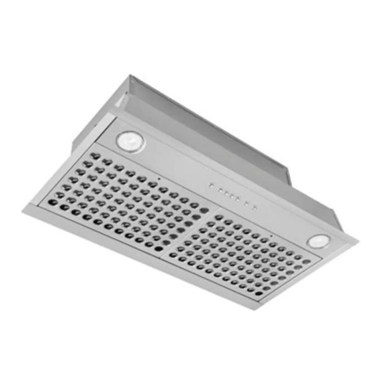
CC6 SERIES
!
!
INTENDED FOR DOMESTIC COOKING ONLY
READ AND SAVE THESE INSTRUCTIONS
INSTALLER: LEAVE THIS MANUAL WITH HOMEOWNER.
HOMEOWNER: USE AND CARE INFORMATION ON PAGES 12 AND 13.
BEST; Hartford, Wisconsin www.BestRangeHoods.com 800-558-1711
BEST; Drummondville, QC, Canada www.BestRangeHoods.ca 866-737-7770
23862 rev. 02
Table des Matières

Manuels Connexes pour Best CC6 Serie


Sommaire des Matières pour Best CC6 Serie
-
Page 17: Lire Et Conserver Ces Directives
CONÇUE UNIQUEMENT POUR LA CUISSON DOMESTIQUE LIRE ET CONSERVER CES DIRECTIVES INSTALLATEUR : LAISSER CE GUIDE AU PROPRIÉTAIRE. PROPRIÉTAIRE : DIRECTIVES D’UTILISATION ET D’ENTRETIEN EN PAGES 12 ET 13. BEST; Hartford, Wisconsin www.BestRangeHoods.com 800 558-1711 BEST; Drummondville, QC, Canada www.BestRangeHoods.ca 866 737-7770 23862 rév. 02... -
Page 18: Afin De Réduire Les Risques De Feu De Cuisinière
9. Afin de réduire les risques d’incendie et d’électrocution, les laissez pas la graisse s’accumuler sur le ventilateur, les filtres modèles Best de la série CC6 doivent être installés uniquement ou les conduits d’évacuation. avec leur propre ventilateur intérieur. Aucun autre ventilateur ne doit être utilisé. -
Page 19: Système De Hotte Encastrable
SÉRIE CC6 SYSTÈME DE HOTTE ENCASTRABLE- ODÈLE APUCHON DE TOIT APUCHON DE MUR ODÈLE APUCHON DE TOIT STANDARD STANDARD APUCHON DE MUR POUR 3¼ 3¼ À HAUT RENDEMENT PO X PO X CONDUIT DE PO ROND NON INCLUS NON INCLUS NON INCLUS NON INCLUS ODÈLE... -
Page 20: Préparer L'installation
1. PRÉPARER L'INSTALLATION AVERTISSEMENT Il est recommandé de porter des lunettes et des gants de sécurité lors de l’installation, de l’entretien ou de la réparation de cet appareil. NOTE: Avant de commencer l'installation, vérifier le contenu de la boîte. Si des pièces sont manquantes ou endommagées, contacter le manufacturier. -
Page 21: Préparer L'armoire
3. PRÉPARER L'ARMOIRE AVERTISSEMENT Toujours suivre les codes et standards en vigueur lors de la contruction de l’armoire pour hotte. La charpente doit être fixée solidement aux montants ou autre structure derrière la cloison. S’assurer qu’elle puisse supporter son propre poids en plus de celui de la hotte encastrable. Ne pas suivre cette directive peut entraîner des blessures corporelles ou des dommages à... -
Page 22: Installer Le Revêtement D'armoire (Optionnel)
4. INSTALLER LE REVÊTEMENT D'ARMOIRE (OPTIONNEL) Les revêtements d’armoire sont spécialement conçus pour protéger l’extérieur de la base de l’armoire. Consulter le tableau ci-dessous afin de trouver le modèle de revêtement correspondant à la largeur nominale de l’armoire. Visiter le site www.BestRangeHoods.com, www.BestRangeHoods.ca, ou contacter le service technique (voir le numéro de téléphone en page couverture) afin de connaître leurs caractéristiques, incluant la profondeur de chacun des modèles. -
Page 23: Débrancher Le(S) Ventilateur(S)
7. DÉBRANCHER LE(S) VENTILATEUR(S) Débrancher le(s) ventilateur(s) du panneau avant (un ou deux, selon le modèle). HE0105 8. RETIRER LE COUVERCLE DU COMPARTIMENT ÉLECTRIQUE ET LE PANNEAU AVANT À l’aide d’un tournevis Robertson ou Phillips n° 2, dévisser les deux vis (A) retenant le couvercle du compartiment électrique. -
Page 24: Installer L'adaptateur/Volet
11. INSTALLER L'ADAPTATEUR/VOLET ( VENTILATEUR SIMPLE SEULEMENT) NSTALLATION À ÉVACUATION VERTICALE À l’aide de 2 vis n° 8 x 3/8 po (incluses dans le sac de pièces), assembler l’adaptateur/volet sur le dessus de la hotte encastrable. Enlever le ruban adhésif sur le volet. Sceller l’adaptateur à la hotte encastrable à... -
Page 25: Retirer Le Ventilateur
13. RETIRER LE VENTILATEUR ( VENTILATEUR SIMPLE, ÉVACUATION HORIZONTALE SEULEMENT) Afin de faciliter l’alignement de la hotte encastrable avec le conduit horizontal, désassembler le ventilateur de la hotte encastrable avant d’installer celle-ci dans l’armoire. MPLACEMENT DES VIS MPLACEMENT DES VIS CÔTÉ... -
Page 26: Installer L'adaptateur/Volet À L'arrière De La Hotte Encastrable
15. INSTALLER L’ADAPTATEUR/VOLET À L’ARRIÈRE DE LA HOTTE ENCASTRABLE (VENTILATEUR SIMPLE, ÉVACUATION HORIZONTALE SEULEMENT) Par l’extérieur du mur, à l’aide de deux vis n° 8 x 3/8 po (incluses dans le sac de pièces), fixer l’adaptateur/volet à l’arrière de la hotte encastrable. -
Page 27: Branchement Électrique
17. BRANCHEMENT ÉLECTRIQUE (TOUS LES MODÈLES) AVERTISSEMENT Risque d’électrocution. Le raccordement électrique doit être effectué par du personnel qualifié conformément aux codes et standards. Avant d’effectuer le branchement, coupez l’alimentation électrique au panneau de distribution et verrouillez-le pour éviter une mise en marche accidentelle. Insérer le câble d’alimentation dans la hotte à... -
Page 28: Remettre Les Filtres En Place
19. REMETTRE LES FILTRES EN PLACE ATTENTION Retirer la pellicule protectrice de plastique des filtres avant de les installer. 1. À l’aide d’un tournevis Phillips n° 2, assembler chaque bouton à son filtre. NOTE : La vis DOIT ÊTRE sur le côté des languettes du filtre. Voir l’illustration ci-contre. HO0139 2. -
Page 29: Fonctionnement
22. FONCTIONNEMENT AVERTISSEMENT Lors de l’utilisation d’une cuisinière au gaz, toujours faire fonctionner le(s) ventilateur(s) de la hotte avant de commencer la cuisson. De plus, le ou les ventilateurs doivent être réglés au moins en troisième vitesse si trois brûleurs ou plus sont en fonction simultanément. La surface de la hotte pourrait devenir très chaude si cet avertissement n’était pas suivi. -
Page 30: Schéma Électrique
23. SCHÉMA ÉLECTRIQUE LIGNE NEUTRE MISE À LA TERRE ODULE TRANSFORMATEUR ’ ALIMENTATION OGIQUE CODE DE COULEUR R 9,5 V BLANC BLEU BRUN ARTE GRIS ÉLECTRONIQUE 120 V JAUNE IGNE NOIR ORANGE ROUGE 10 V MOTEUR DU VENTILATEUR DEUXIÈME MOTEUR DU VENTILATEUR (OPTIONNEL) HE0162F... -
Page 31: Pièces De Remplacement
24. PIÈCES DE REMPLACEMENT CC65I28SB CC67I28SB HL0447 TÉ ODÈLE DE HOTTE ENCASTRABLE DE PIÈCE ESCRIPTION RÉF CC65I28SB CC67I28SB SV13296 3¼ X 10 DAPTATEUR VOLET SV08541 DAPTATEUR PO ROND 62248 ODULE D ALIMENTATION ET FAISCEAU DE CONNECTION SV21244 OMMANDE ÉLECTRONIQUE AVEC BOUTONS CHROMÉS ET BLEUES 62612 DEL (1) -
Page 32: Garantie
25. GARANTIE GARANTIE LIMITÉE DE 5 ANS SUR LES PRODUITS BEST Période de garantie et exclusions : Broan-NuTone LLC (l’« entreprise ») garantit au consommateur qui achète son produit (« vous ») que le produit (le « produit ») restera exempt de défauts importants dans ses composants ou sa fabrication pendant une période de cinq (5) ans à... - Page 33 DESTINADA ÚNICAMENTE PARA COCINAS DOMÉSTICAS LEA Y GUARDE ESTAS INSTRUCCIONES INSTALADOR: DEJE ESTE MANUAL AL PROPIETARIO. PROPIETARIO: INFORMACIÓN SOBRE USO Y CUIDADO EN LAS PÁGINAS 12 Y 13. BEST; Hartford, Wisconsin www.BestRangeHoods.com 800-558-1711 BEST; Drummondville, QC, Canada www.BestRangeHoods.ca 866-737-7770 23862 rev. 02...