Table des Matières

Publicité

Les langues disponibles

Les langues disponibles

Liens rapides

8038559
IO-Link DA-Interface
MPS
®
Accessories
Betriebsanleitung
Operating instructions
Manual de instrucciones
Notice d'utilisation
Festo Didactic
8038560 de/en/es/fr
12/2014

Publicité

Table des Matières
loading

Sommaire des Matières pour Festo 8038559

  • Page 1 8038559 IO-Link DA-Interface ® Accessories Betriebsanleitung Operating instructions Manual de instrucciones Notice d'utilisation Festo Didactic 8038560 de/en/es/fr 12/2014...
  • Page 2 12/2014 Author: Andreas Hemminger Layout: Susanne Durz, Frank Ebel © Festo Didactic SE, Rechbergstraße 3, 73770 Denkendorf, Germany, 2019 +49 711 3467-0 www.festo-didactic.com +49 711 34754-88500 did@de.festo.com The copying, distribution and utilization of this document as well as the communication of its contents to others without expressed authorization is prohibited.
  • Page 3: Table Des Matières

    Gerätestatus ______________________________________________________________________ 9 Systemübersicht Hardware __________________________________________________________ 9 Steuerungsebene __________________________________________________________________ 9 Feldbusebene ____________________________________________________________________ 10 Verdrahtungsebene _______________________________________________________________ 10 CTEU-Module _____________________________________________________________________ 11 Integration in die Programmierumgebung CoDeSys ______________________________________ 12 IO-Link DA-Interface Signalanschlüsse ________________________________________________ 18 12.1 M12-Stecker mit I-Port Schnittstelle __________________________________________________ 19 © Festo Didactic 8038560...
  • Page 4: Gewährleistung Und Haftung

    Schäden vorsätzlich oder grob fahrlässig verursacht. 2 Bestimmungsgemäße Verwendung Das Lernsystem von Festo Didactic ist ausschließlich für die Aus- und Weiterbildung im Bereich Automatisierung und Technik entwickelt und hergestellt. Das Ausbildungsunternehmen und/oder die Ausbildenden hat/haben dafür Sorge zu tragen, dass die Auszubildenden die Sicherheitsvorkehrungen, die in den begleitenden Handbüchern beschrieben sind, beachten.
  • Page 5: Sicherheitshinweise

    Das IO-Link DA-Interface bildet die Schnittstelle von industriellen Feldbussen zu digitalen und analogen Ein- /Ausgangssignalen. Für die jeweiligen Feldbustypen können die endsprechenden Feldbusköpfe „CTEU“ von Festo mit dem Gerät verbunden werden. Eine IO-Link-fähige Steuerung kann das Gerät auch ohne weitere Komponenten ansprechen. Beispielsweise kann die Festo-Steuerung CECC-LK eingesetzt werden, um mit dem IO-Link DA-Interface zu kommunizieren.
  • Page 6: Transport/Auspacken/Lieferumfang

    Das IO-Link DA-Interface wird in einem Karton Montageteilen geliefert. Der Karton muss gegen Umfallen und Herunterfallen gesichert sein. Transportschäden sind unverzüglich dem Spediteur und Festo Didactic zu melden. 5.2 Auspacken Nach dem Auspacken des IO-Link DA-Interface auf mögliche Beschädigungen überprüfen. Beschädigungen sind unverzüglich dem Spediteur und Festo Didactic zu melden.
  • Page 7: Montage

    Verwenden Sie nur das beigelegte Montagematerial. Längere Schrauben könnten die Elektronik zerstören! 6.3 Feldmontage über Montageblech Montieren Sie das Montageblech mittels der beigelegten Schrauben und Unterlegescheiben an der Geräterückwand. Achtung Verwenden Sie nur das beigelegte Montagematerial. Längere Schrauben könnten die Elektronik zerstören! © Festo Didactic 8038560...
  • Page 8: Geräteübersicht Io-Link Da-Interface

    IO-Link DA interface – Betriebsanleitung 7 Geräteübersicht IO-Link DA-Interface Grundgerät mit integrierter I-Port Schnittstelle zur direkten Verbindung zu einer SPS mit IO-Link-Schnittstelle. Grundgerät mit zusätzlichem Feldbusinterface z. B. „CTEU-CO“ für die Integration in ein CAN-Open Netzwerk. © Festo Didactic 8038560...
  • Page 9: Gerätestatus

    Rot blitzend IO-Link Versorgung nicht angeschlossen. L+ Signal an Klemme X12, X13, X14 oder X15 nicht angeschlossen und Betriebsspannung für Schaltausgänge nicht aktiv. IO-Link DA-Interface nicht angeschlossen 9 Systemübersicht Hardware 9.1 Steuerungsebene Z. B. Festo CECC-LK Steuerung © Festo Didactic 8038560...
  • Page 10: Feldbusebene

    IO-Link DA interface – Betriebsanleitung 9.2 Feldbusebene IO-Link DA-Interface mit optionalen Feldbusköpfen 9.3 Verdrahtungsebene Z. B. Mini-I/O-Terminal © Festo Didactic 8038560...
  • Page 11: Cteu-Module

    CTEU-DN CTEU-EC Feldbustechnologie: Device Net Feldbustechnologie: EtherCat Bestell-Nr.: 570039 Bestell-Nr.: 572556 Die technischen Daten, Dokumentation, Software und Treiber können auf der Homepage von Festo bezogen werden. Unter www.festo.com kann das gewünschte Modul, z. B. CTEU-PB unter „Website durchsuchen“ eingegeben werden.
  • Page 12: Integration In Die Programmierumgebung Codesys

    IODD-Datei enthält Informationen zur Identifikation, Geräteparametern, Prozess- und Diagnosedaten, Kommunikationseigenschaften und den Aufbau des Anwender-Interfaces in Engineering Tools wie CoDeSys. Die aktuelle IODD-Konfigurationsdatei liegt unter www.festo-didactic.com/service/mps Diese folgende Beschreibung orientiert sich an der CoDeSys-Version «3.5 SP3 Patch2 pbF». Bei anderen Versionen kann eine abweichende Benutzerführung möglich sein.
  • Page 13 Projektname vergeben; unter kann ein Speicherort angegeben werden. CECC Projekt Unter Vorlagen Doppelklick auf Unter Gerät ist die CECC-LK-Steuerung auszuwählen. Die Programmiersprache kann frei gewählt werden. IO-Link Master hinzufügen Die Auswahl muss gesetzt sein © Festo Didactic 8038560...
  • Page 14 Position im Gerätebaum markiert. Im Beispiel ist das DA-Interface an X12 angeschlossen und die oberste Position unter IO-Link Master ist markiert. Über die rechte Maustaste kann ein Menü aktiviert werden; hier ist der Punkt « Gerät setzen » zu aktivieren. © Festo Didactic 8038560...
  • Page 15 IO-Link DA interface – Betriebsanleitung Die dargestellte Maske wird angezeigt und mit dem Button « Gerät setzen » bestätigt. © Festo Didactic 8038560...
  • Page 16 IO-Link DA interface – Betriebsanleitung In Online Mode wird das eingebundene IO-Link-DA-Interface angezeigt. Unter der Registrierkarte IO-Link Parameter werden können verschiedene Eigenschaften des IO-Link-DA-Interface ausgelesen werden. Mit dem Button « Diese Seite lesen » kann die Anzeige aktualisiert werden. © Festo Didactic 8038560...
  • Page 17 IO-Link DA interface – Betriebsanleitung Unter der Registrierkarte IO-Link I/O-Abbild werden alle Variablen angezeigt und können auch geschrieben werden. Damit die dargestellten Prozessdaten mit der Hardware übereinstimmen, muss das Auswahlfeld « Variablen immer aktualisieren » im Offlinemode gesetzt werden. © Festo Didactic 8038560...
  • Page 18: Io-Link Da-Interface Signalanschlüsse

    (IO-Link) Mechanische Daten Abmessungen 91,5 x 128,3 x 30mm Gewicht 240g Schutzart Mit Blechhaube, IP 20 Im 19‘‘-Rahmen mit CTEU montiert IP 40 CE-Zeichen Nach EU/EMV Richtlinie Zulässige Umgebungstemperatur Betrieb 5…40°C Technische Daten des IO-Link-DA-Interface allgemein © Festo Didactic 8038560...
  • Page 19: M12-Stecker Mit I-Port Schnittstelle

    Belegung D-Sub HD Port A und Port B 12.1 M12-Stecker mit I-Port Schnittstelle Benennung Beschreibung 24VB +24V Eingänge / Logik 24VA +24V Ausgänge / Last GND B 0V Eingänge / Logik IO-Link Signal GND A 0V Ausgänge / Last Belegung M12-Stecker, 5-polig, A-codiert © Festo Didactic 8038560...
  • Page 20 IO-Link DA interface – Betriebsanleitung © Festo Didactic 8038560...
  • Page 21 Control level _____________________________________________________________________ 27 Fieldbus level ____________________________________________________________________ 28 Wiring level ______________________________________________________________________ 28 Modules CTEU ____________________________________________________________________ 29 Integration into the CoDeSys programming environment _________________________________ 30 IO-Link D/A interface signal connections _______________________________________________ 36 12.1 M12 plug with I-Port interface _______________________________________________________ 37 © Festo Didactic 8038560...
  • Page 22: Guarantee And Liability

    Disasters resulting from the influence of foreign bodies and acts of God Festo Didactic hereby excludes any and all liability for damages suffered by trainees, the training company and/or any third parties, which occur during use of the IO-Link D/A interface in situations which serve any purpose other than training and/or vocational education, unless such damages have been caused by Festo Didactic due to malicious intent or gross negligence.
  • Page 23: Safety Instructions

    The IO-Link D/A interface is used as an interface between industrial fieldbuses and digital and analogue I/O signals. Festo’s corresponding fieldbus modules CTEU for the respective fieldbus types can be connected to the device. An IO-Link-compatible controller can address the device without the help of any other components. For example, the Festo controller CECC-LK can be used to communicate with the IO-Link D/A interface.
  • Page 24: Transport, Unpacking, Scope Of Delivery

    Three M3x30 screws for mounting a bus node CTEU • Assembly materials for mounting bracket and H-rail socket • Manual for IO-Link D/A interface Check delivered items against the packing slip and your purchase order. Notify Festo Didactic of any deviations without delay. © Festo Didactic 8038560...
  • Page 25: Mounting

    6.3 Mounting in the field via mounting plate Attach the mounting plate to the back of the device using the included screws and washers. Attention Use only the mounting materials included. Longer screws may destroy the electronics! © Festo Didactic 8038560...
  • Page 26: Device Overview, Io-Link D/A Interface

    IO-Link DA interface – Operating instructions 7 Device overview, IO-Link D/A interface Basic unit with integrated I-Port interface for direct connection to a PLC with IO-Link interface. Basic unit with additional fieldbus interface, e.g. CTEU-CO for integration into a CAN-Open network. © Festo Didactic 8038560...
  • Page 27: Device Status

    IO-Link power supply not connected. L+ signal not connected to terminal X12, X13, X14 or X15 and operating voltage for switching outputs is off. IO-Link D/A interface not connected 9 Overview system hardware 9.1 Control level For example Festo controller CECC-LK © Festo Didactic 8038560...
  • Page 28: Fieldbus Level

    IO-Link DA interface – Operating instructions 9.2 Fieldbus level IO-Link D/A interface with optional fieldbus modules 9.3 Wiring level For example mini I/O terminal © Festo Didactic 8038560...
  • Page 29: Modules Cteu

    Fieldbus technology: Device Net Fieldbus technology: EtherCat Order number: 570039 Order number: 572556 Technical data, documentation, software and drivers can be downloaded from Festo’s website. The required module, e.g. CTEU-PB, can be entered under “Search website” at www.festo.com. © Festo Didactic 8038560...
  • Page 30: Integration Into The Codesys Programming Environment

    CoDeSys. The current IODD configuration file can be accessed at www.festo-didactic.com/service/mps. The following description is based on CoDeSys version “3.5 SP3 patch2 pbF”. User prompting may vary for other versions.
  • Page 31 CECC project Templates Double click the icon under Device Select the controller CECC-LK from the drop-down list. The programming language can be selected from the list. Add IO-Link master The checkbox next to must be activated. © Festo Didactic 8038560...
  • Page 32 IO-Link D/A interface is connected to. In our example, the D/A interface is connected to port X12 and the top item under the IO-Link master is selected. A menu can be activated by right clicking, in which case “Set device” must be activated. © Festo Didactic 8038560...
  • Page 33 IO-Link DA interface – Operating instructions The window shown above appears and is acknowledged by clicking “Set device”. © Festo Didactic 8038560...
  • Page 34 The integrated IO-Link D/A-interface is displayed in the online mode. Various characteristics of the IO-Link D/A interface can be read out in the “IO-Link parameters” tab. The display can be refreshed by clicking the “Read this page” button. © Festo Didactic 8038560...
  • Page 35 All variables are displayed in the “IO-Link I/O map” tab and can be edited as well. In order to ensure that the displayed process data coincide with the hardware, “Always update variables” must be selected in the offline mode. © Festo Didactic 8038560...
  • Page 36: Io-Link D/A Interface Signal Connections

    With cover plate IP 20 Mounted in 19" rack with CTEU IP 40 CE marking In accordance with EU EMC directive Permissible ambient temperature during operation 5 … 40° C General technical data, IO-Link D/A interface © Festo Didactic 8038560...
  • Page 37: M12 Plug With I-Port Interface

    12.1 M12 plug with I-Port interface Designation Description 24VB +24 V inputs, logic 24 VA +24 V outputs, load GND B 0 V inputs, logic IO-Link Signal GND A 0 V outputs, load Pin assignments, 5-pin M12 plug, A coded © Festo Didactic 8038560...
  • Page 38 IO-Link DA interface – Operating instructions © Festo Didactic 8038560...
  • Page 39 Nivel de bus de campo _____________________________________________________________ 47 Nivel de cableado _________________________________________________________________ 47 Módulos CTEU ____________________________________________________________________ 48 Integración en la programación con CoDeSys ___________________________________________ 49 Conexiones de señales, IO-Link DA-Interface ___________________________________________ 55 12.1 Interfaz I-Port con conector M12 tipo clavija ____________________________________________ 56 © Festo Didactic 8038560...
  • Page 40: Garantía Y Responsabilidades

    IO- Link DA-Interface se realiza con propósitos que no son de instrucción, a menos que Festo Didactic haya ocasionado dichos daños premeditadamente o con extrema negligencia.
  • Page 41: Indicaciones De Seguridad

    IO-Link DA-Interface establece la unión entre buses de campo industriales y señales digitales y analógicas de entrada/salida. Según tipo de bus de campo se pueden seleccionar los módulos CTEU de Festo que correspondan, para establecer la conexión con IO-Link DA-Interface.
  • Page 42: Transporte / Desembalaje / Dotación Del Suministro

    La unidad IO-Link DA-Interface se entrega en un cartón, incluidas las piezas necesarias para su montaje. Durante el transporte, el cartón debe asegurarse de tal manera que no se ladee o se caiga. Cualquier daño ocurrido durante el transporte deberá notificarse de inmediato al transportista y a Festo Didactic.
  • Page 43: Montaje

    Fije la chapa de montaje al dorso de la unidad, utilizando los tornillos que se incluyen con ese fin en el suministro. Atención Para realizar el montaje, utilice únicamente el material incluido con ese fin en el suministro. ¡Si utiliza tornillos más largos podría destruir los componentes electrónicos! © Festo Didactic 8038560...
  • Page 44: Cuadro General Del Producto Io-Link Da-Interface

    Unidad básica con interfaz I-Port integrada, para la conexión directa a un PLC con interfaz IO-Link. Unidad básica con interfaz de bus de campo adicional (por ejemplo, módulo CTEU-CO) para la integración en una red CANopen. © Festo Didactic 8038560...
  • Page 45: Estado Del Dispositivo

    X12, X13, X14 o X15, y tensión de funcionamiento para salidas conmutadas no conectada. Unidad IO-Link DA-Interface no conectada. 9 Cuadro general del sistema, hardware 9.1 Nivel de control Por ejemplo, unidad de control CECC-LK de Festo © Festo Didactic 8038560...
  • Page 46: Nivel De Bus De Campo

    Interfaz DA IO-Link – Manual de instrucciones 9.2 Nivel de bus de campo IO-Link DA-Interface con módulos de bus de campo opcionales 9.3 Nivel de cableado Por ejemplo, terminal MINI-I/O © Festo Didactic 8038560...
  • Page 47: Módulos Cteu

    N° de art.: 572556 Los datos técnicos, la documentación, el software y los controladores están disponibles en la página web de Festo. Introducir en www.festo.com el módulo deseado (por ejemplo, CTEU-PB) en "Buscar en página web". © Festo Didactic 8038560...
  • Page 48: Integración En La Programación Con Codesys

    CoDeSys. El archivo actualizado IODD para la configuración está disponible en www.festo-didactic.com/service/mps. La descripción se rige por la versión de CoDeSys <3.5 SP3 Patch2 pbF>. En otras versiones puede variar la interfaz de usuario.
  • Page 49 Proyecto CECC En <Plantillas> haga clic en Equipo deberá seleccionarse la unidad de control CECC-LK. El lenguaje de programación puede elegirse libremente. Agregar master IO-Link Confirmar © Festo Didactic 8038560...
  • Page 50 Interface, se marca la correspondiente posición en la ramificación. En el ejemplo, la unidad DA-Interface está conectada a X12, por lo que está marcada la posición superior en el master IO-Link. Haciendo clic con el botón derecho se puede activar un menú. En él, deberá marcarse <Activar unidad>. © Festo Didactic 8038560...
  • Page 51 Interfaz DA IO-Link – Manual de instrucciones Aparece la máscara que se muestra en la imagen. Activar <Conectar aparato>. © Festo Didactic 8038560...
  • Page 52 Interfaz DA IO-Link – Manual de instrucciones En el modo online, se muestra la unidad IO-Link DA-Interface. En la pestaña <Parámetros IO-Link> pueden leerse diversas propiedades de la unidad IO-Link DA-Interface. Con el botón <Leer esta página> se actualizan los datos. © Festo Didactic 8038560...
  • Page 53 En la pestaña <IO-Link Imagen I/O> se muestran todas las variables. Además, es posible introducir textos. Para que los datos del proceso que se muestran coincidan con el hardware, debe confirmarse <Actualizar siempre las variables> en el modo offline. © Festo Didactic 8038560...
  • Page 54: Conexiones De Señales, Io-Link Da-Interface

    Tapa de chapa, IP 20 Montaje en bastidor de 19° junto con módulo CTEU IP 40 Símbolo CE Según la directiva UE sobre CEM Temperatura ambiente permitida 5…40°C Datos técnicos generales de la unidad IO-Link DA-Interface © Festo Didactic 8038560...
  • Page 55: Interfaz I-Port Con Conector M12 Tipo Clavija

    12.1 Interfaz I-Port con conector M12 tipo clavija Denominación Descripción 24VB Entradas de +24V / lógica 24VA +24V salida / carga GND B Entradas de 0V / lógica IO-Link; Señal GND A 0V salida / carga Ocupación conector M12, 5 contactos, codificación A © Festo Didactic 8038560...
  • Page 56 Interfaz DA IO-Link – Manual de instrucciones © Festo Didactic 8038560...
  • Page 57 Niveau bus de terrain ______________________________________________________________ 64 Niveau câblage ___________________________________________________________________ 64 Modules CTEU ____________________________________________________________________ 65 Intégration dans l'environnement de programmation CoDeSys _____________________________ 66 Ports de signal sur interface IO-Link DA ________________________________________________ 72 12.1 Connecteur mâle M12 avec interface I-Port _____________________________________________ 73 © Festo Didactic 8038560...
  • Page 58: Garantie Et Responsabilité

    à une négligence grossière de Festo Didactic. 2 Usage normal Le système de formation de Festo Didactic est exclusivement destiné à la formation initiale et continue dans le domaine de l’automatisation et de la technique. Il incombe à l’établissement de formation et/ou aux formateurs de faire respecter par les étudiants les consignes de sécurité...
  • Page 59: Instructions De Sécurité

    L'interface IO-Link DA constitue l'interface entre les bus de terrain industriels et les signaux d'entrée/sortie TOR et analogiques. Des nœuds de bus de terrain « CTEU » Festo, correspondant aux divers types de bus de terrain, peuvent être connectés à l'appareil.
  • Page 60: Transport/Déballage/Fourniture

    L'interface IO-Link DA est livrée, avec accessoires de montage, dans un carton. Veillez à ce que le carton ne se renverse pas, ni ne tombe. Tout dommage dû au transport doit être immédiatement signalé au transporteur et à Festo Didactic. 5.2 Déballage Vérifiez, après déballage, que l'interface IO-Link DA n'a pas été...
  • Page 61: Montage

    6.3 Montage sur plaque de fixation Montez la plaque de fixation à l'aide des vis et rondelles fournies au dos de l'appareil. Attention Utilisez uniquement les accessoires de montage fournis. Des vis plus longues risqueraient de détériorer l'électronique. © Festo Didactic 8038560...
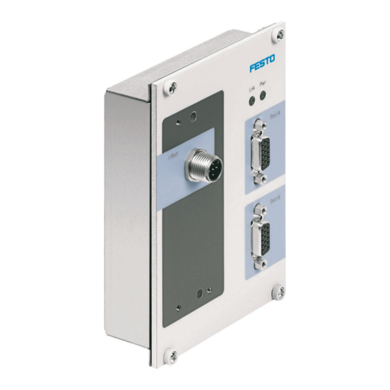
  • Page 62: Présentation De L'interface Io-Link Da

    Appareil de base à interface I-Port intégrée pour la connexion directe à un API équipé d'une interface IO-Link. Appareil de base avec interface de bus de terrain additionnelle, « CTEU-CO » p. ex., pour intégration dans un réseau CAN-Open. © Festo Didactic 8038560...
  • Page 63: État De L'appareil

    X12, X13, X14 ou X15 et la tension de service des sorties TOR n'est pas activée. Hors tension Hors tension Interface IO-Link DA non connectée 9 Matériel du système 9.1 Niveau automate Automate CECC-LK Festo p. ex. © Festo Didactic 8038560...
  • Page 64: Niveau Bus De Terrain

    Interface DA IO-Link – Notice d'utilisation 9.2 Niveau bus de terrain Interface IO-Link DA avec nœuds de bus de terrain en option 9.3 Niveau câblage Miniterminal I/O p. ex. © Festo Didactic 8038560...
  • Page 65: Modules Cteu

    Réf. : 570039 Réf. : 572556 Les caractéristiques techniques, la documentation, le logiciel et les pilotes sont téléchargeables à partir du site Festo. Sous www.festo.com, vous pouvez spécifier le module souhaité, CTEU-PB p. ex., dans « Rechercher ». © Festo Didactic 8038560...
  • Page 66: Intégration Dans L'environnement De Programmation Codesys

    CoDeSys. Le fichier de configuration IODD actuel se trouve sous www.festo-didactic.com/service/mps. La description ci-après est basée sur la version CoDeSys «3.5 SP3 Patch2 pbF». Le guide-utilisateur des autres versions peut être différent de celui décrit ci-après.
  • Page 67 Effectuez sous Modèles un double-clic sur CECC Project Sélectionnez sous Device l'automate CECC-LK. Sélectionnez le langage de programmation que vous souhaitez utiliser. Add IO-Link Master L'option doit être cochée © Festo Didactic 8038560...
  • Page 68 Dans l'exemple, l'interface DA est connectée à X12 et la position tout en haut sous le maître IO-Link est repérée. Le bouton droit de la souris permet d'ouvrir un menu ; sélectionnez dans ce menu l'option « Connecter l'appareil ». © Festo Didactic 8038560...
  • Page 69 Interface DA IO-Link – Notice d'utilisation La boîte de dialogue représentée s'affiche ; validez-la avec le bouton « Connecter l'appareil ». © Festo Didactic 8038560...
  • Page 70 Interface DA IO-Link – Notice d'utilisation En mode en ligne, l'interface IO-Link DA connectée est affichée. L'onglet IO-Link Parameter affiche diverses propriétés de l'interface IO-Link DA. Le bouton « Read this page » permet d'actualiser l'affichage. © Festo Didactic 8038560...
  • Page 71 L'onglet IO-Link Mappage E/S affiche toutes les variables et permet de les éditer. Pour que les données de process représentées correspondent bien au matériel, la case « Toujours actualiser les variables » doit être cochée en mode hors ligne. © Festo Didactic 8038560...
  • Page 72: Ports De Signal Sur Interface Io-Link Da

    Degré de protection Avec capot de tôle, IP 20 Monté sur châssis 19" avec CTEU IP 40 Marquage CE Selon directive CEM européenne Température ambiante admissible en service 5…40 °C Caractéristiques techniques générales de l'interface IO-Link DA © Festo Didactic 8038560...
  • Page 73: Connecteur Mâle M12 Avec Interface I-Port

    Entrées +24 V / logique 24VA Sorties +24 V / charge GND B Entrées 0 V / logique IO-Link Signal GND A Sorties 0 V / charge Brochage connecteur mâle M12, à 5 pôles, codé A © Festo Didactic 8038560...
  • Page 74 Interface DA IO-Link – Notice d'utilisation © Festo Didactic 8038560...
  • Page 76 Festo Didactic SE Rechbergstraße 3 73770 Denkendorf Germany +49 711 3467-0 www.festo-didactic.com +49 711 34754-88500 did@festo.com...

Table des Matières