Chapitres
Table des Matières
Dépannage

Manuels Connexes pour Ultraflex UP 18


Sommaire des Matières pour Ultraflex UP 18
- Page 1 Installation and Maintenance Manual PUMP FOR HYDRAULIC STEERING SYSTEMS UP 18 PARTNER page 2 pag.31 page 61 (dr./dis./des. n° 30084b - 04/02/2015) (REV 02 - 04/02/2015)
- Page 2 Dear Customer, Thank you for choosing one of our products has long been a landmark in steering systems in the field of both leisure and professional boating. Always production is synonymous with great reliability and safety. All products are designed and manufactured to guarantee the best performance possible, according to the purposes they are designed and intended for.
-
Page 3: Table Des Matières
Installation and Maintenance Manual GENERAL INDEX DOCUMENT REVISIONS..........................4 USE OF THE MANUAL AND SYMBOLS USED.....................5 INFORMATION LETTER..........................6 WARRANTY..............................7 SECTION 1 - PRODUCT DESCRIPTION OPERATION OF A HYDRAULIC STEERING SYSTEM..............8 INFORMATION FOR CORRECT USE OF THE PRODUCT..............9 SYSTEM CONFIGURATIONS......................9 DESCRIPTION PUMP......................10 TECHNICAL FEATURES......................11 SECTION 2 - TRANSPORT GENERAL WARNINGS FOR PRODUCT HANDLING..............12... -
Page 4: Document Revisions
Installation and Maintenance Manual DOCUMENT REVISIONS REV. DATE REVISION DESCRIPTION 12/09/2013 First edition. 07/05/2014 Upgrade to 39kn (45mph). 04/02/2015 Update compatible oils. page PUMP FOR HYDRAULIC SYSTEMS... -
Page 5: Use Of The Manual And Symbols Used
Installation and Maintenance Manual USE OF THE MANUAL AND SYMBOLS USED The INSTALLATION AND MAINTENANCE MANUAL is the document accompanying the product from the time of its sale until replacement and disposal. It must be therefore considered an integral part of it. It is recommended to read the manual before carrying out ANY ACTIVITIES involving the product, including its handling and unloading from the vehicle. -
Page 6: Information Letter
Installation and Maintenance Manual INFORMATION LETTER This installation and maintenance manual is an integral part of the product and must be readily available for use by staff appointed to both use and maintenance. The user is required to be familiar with the contents of this manual. disclaims any liability for inaccuracies due to typographical errors in the manual. -
Page 7: Warranty
Installation and Maintenance Manual WARRANTY warrants that its products are manufactured in a workmanlike manner and that they are free from defects in workmanship and materials. This warranty is valid for a period of 2 years from the date of manufacture of the products, with the exception of cases in which they are installed and used on working boats or in any case on boats used for commercial purposes, in which case the warranty is limited to 1 year from the date of manufacture. -
Page 8: Operation Of A Hydraulic Steering System
Installation and Maintenance Manual 1 - PRODUCT DESCRIPTION 1.1 Operation of a hydraulic steering system The hydraulic systems are designed in accordance with UNI EN ISO 10592 rule and A.B.Y.C. standards P21. The steering systems are able to operate in an ambient temperature ranging between -18°C (0°F) and +77°C (+170°F), all of their components were specifically manufactured for the marine environment, using materials and applying processes that offer great durability and safety even in extreme conditions. -
Page 9: Information For Correct Use Of The Product
Installation and Maintenance Manual 1.2 INFORMATION FOR CORRECT USE OF THE PRODUCT DANGER In any case do not make changes to the pump in order to make it better suit your specific application. In this case the pump will not operate safely and endanger the boat and its occupants. -
Page 10: Description Pump
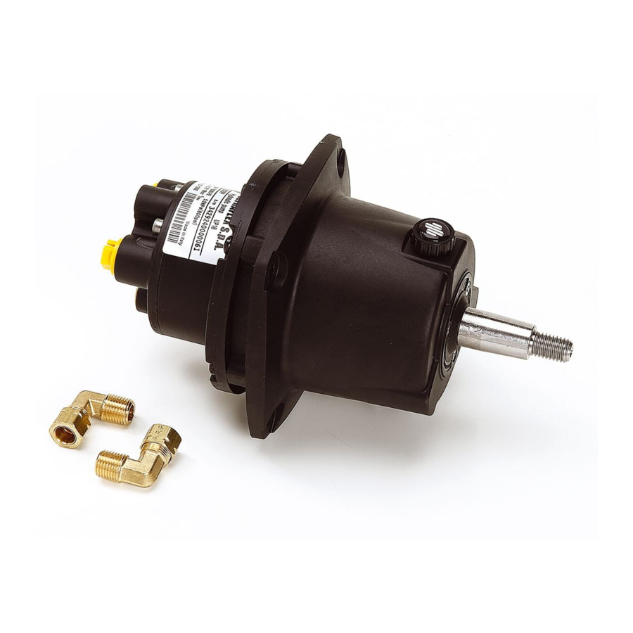
Installation and Maintenance Manual 1.4 Description pump The UP18 pump was designed and built to be used as a component of a hydraulic steering system as described in the previous paragraph and mounted on the front dashboard. The following picture shows the main components of the pump. UP18 pump Fuel tank cap Key for steering wheel hub... -
Page 11: Technical Features
508 mm - (20 in) Steering wheel max. socket 115 mm - (4,5 in) Weight 3,8 kg OL150 ULTRAFLEX 94 mm / 3,7 in 138 mm / 5,4 in 56 mm / 2,2 in 130 mm / 5,1 in Ø 115 mm CAUTION The pressure max. -
Page 12: General Warnings For Product Handling
Installation and Maintenance Manual 2 - TRANSPORT 2.1 General warnings for product handling The weight of the product, including the packaging, is 3,8 kg and therefore it can be handled manually. CAUTION The staff handling the load must operate using all required PPE (Personal Protective Devices) as required by the applicable standard on accident prevention at the workplace. -
Page 13: Tools Required For Installation
Installation and Maintenance Manual 3 - INSTALLATION 3.1 Tools required for installation Open end wrench Open end wrench Open end wrench 7/16” 19mm 10mm Joint sealing Loctite MOLYKOTE ® 1000 Torque wrench 542/545 Drill page PUMP FOR HYDRAULIC SYSTEMS -... -
Page 14: Pump Installation
Installation and Maintenance Manual 3.2 Pump installation Choose a position suitable to install the steering station.Check there is sufficient space to move the steering wheel and enough space for the pump with the hoses and joints assembled. minimum 100 mm - (4”) dashboard min thickness 12.7 mm (0.5”) dashboard max thickness... - Page 15 Installation and Maintenance Manual Remove the yellow protective plugs with a screwdriver. CAUTION The plug (1) must only be removed during the auto-pilot installation phase. Apply a Loctite 542 or Loctite 545 sealant on the threads of the elbow fittings (2). page PUMP FOR HYDRAULIC SYSTEMS -...
- Page 16 Installation and Maintenance Manual Insert and tighten by hand the elbow fittings until they are fully seated, then tighten with a 7/16" hex wrench, screwing again from 1.5 to 2.5 turns, up to their best positioning for hoses connection. However do not exceed a max. torque of 17.6 Nm (13 lb ft). CAUTION Do not use Teflon tape or any other type of tape.
- Page 17 Installation and Maintenance Manual Using the template accompanying this user manual make on the dashboard the 4 holes (3) for the screws and the centre hole (4). Position the pump (5) from the front of the dashboard (6) with the tank plug turned upwards.
- Page 18 Installation and Maintenance Manual Use the 4 fastening screws (7), the 4 washers (8) and the 4 self-locking nuts (9), to fasten the pump to the dashboard. Tighten the nuts using a 10 mm wrench with a 10 Nm (7.4 lb ft) torque. CAUTION If the self-locking nuts are removed (9), they must be replaced.
- Page 19 Installation and Maintenance Manual Fit the steering wheel (11), supplied separately, on the shaft (12) by inserting the specific key (13) in its compartment. Insert the washer (14) and use a 19mm hexagonal wrench to tighten the self-locking nut (15) with a 40 Nm (29.5 lb ft) torque: before screwing in the nut, you are advised to apply some galling- proof grease, such as MOLYKOTE®...
-
Page 20: Connecting The Hoses To The System
Installation and Maintenance Manual 3.3 Connecting the hoses to the system Connect the ULTRAFLEX hydraulic hoses to the pump and the cylinder included in the main GOTECH™ packaging, following the instructions in the installation manual of the UC81cylinder and the manual installation of the hoses. -
Page 21: Filling And Bleeding
Installation and Maintenance Manual 3.4 Filling and bleeding After the first installation and after any maintenance you must fill the system with hydraulic oil. This operation is intended to completely remove the air from the system ensuring its proper operation. The hydraulic system must be filled from the highest point of the system. After filling, wait 24 hours and vent again to eliminate any air bubbles in the hydraulic system. -
Page 22: Positioning The Oil Bottle
Installation and Maintenance Manual NOT E will not guarantee compatibility of the cited oils with OL150 in the event of a change in the formulation by the producers of these oils; in particular, it will not guarantee compliance with ISO 10592 relating to hydraulic steering systems. -
Page 23: Bleeding Procedure
Installation and Maintenance Manual 3.4.2 Bleeding procedure Perform the bleeding procedure as described in the installation and maintenance manual relating to the UC81 cylinder, finally get a proper oil level by turning the steering wheel 1/2 turn and letting the oil bleed from the valve. -
Page 24: Safety Precautions During Installation And Use
Installation and Maintenance Manual 4 - SAFETY WARNINGS This section aims to illustrate the safety rules to be followed for proper use of the equipment. It is recommended to read this section very carefully. It is recommended to read the manuals supplied with the other components of the steering system. -
Page 25: Clothing
Installation and Maintenance Manual 4.2 CLOTHING CAUTION During the installation, inspection or maintenance IT IS STRICTLY PROHIBITED wear necklaces, bracelets or clothing that could being caught in moving parts. CAUTION The staff handling the load must operate using all required PPE (individual protection devices) as required by the applicable standard on accident prevention at the workplace. -
Page 26: Routine Maintenance
3.5 - “Filling and bleeding.” Cleanse the system using water and mild and non-abrasive soap. CAUTION Use only OL150 ULTRAFLEX oil, or compatible hydraulic oils, as referred to in "Filling and bleeding" sections. 5.2 Removing the steering wheel Use a specific extractor to remove the steering wheel from the pump shaft. -
Page 27: Troubleshooting
Installation and Maintenance Manual 5.3 Troubleshooting CAUTION Whenever the following checks require the removal and / or disassembly of the components of the steering system, fffffrequest for the assistance of qualified staff. provides general guidance and can not be held responsible for any information or consequences resulting from improper disassembly. - Page 28 Installation and Maintenance Manual PROBLEM POSSIBLE CAUSE INTERVENTION The steering gear is stiff and • Narrowing in the hoses or • Search for the problem and difficult to manoeuvre, even fittings. solve it. when the boat is stationary. • Presence of air in the oil. •...
- Page 29 Installation and Maintenance Manual PROBLEM POSSIBLE CAUSE INTERVENTION By turning the steering • Presence of air in the • Repeat the filling and wheel, the cylinder rod is not system. bleeding procedures of the moving. system. • Oil leaks. • Search for the leak and contact qualified staff.
-
Page 30: Dismantling
Installation and Maintenance Manual 6 - DISMANTLING 6.1 Dismantling If for any reason the equipment is meant to be disposed of, it is necessary to observe some basic rules aimed at safeguarding the environment. CAUTION Sheathings, hoses, conduits and plastic components, or in any case not made with metal, shall be disassembled and disposed of separately. - Page 31 Manuale di installazione e manutenzione POMPA PER SISTEMI DI GUIDA IDRAULICI UP 18 PARTNER...
- Page 32 Gentile Cliente, La ringraziamo per aver scelto un prodotto è da anni un punto di riferimento nei sistemi di guida nel settore della nautica da diporto e professionale. Da sempre la produzione è sinonimo di grande affidabilità e sicurezza. Tutti i prodotti sono progettati e prodotti per garantire sempre le prestazioni migliori, relativamente allo scopo per cui sono concepiti.
- Page 33 Manuale di installazione e manutenzione INDICE GENERALE REVISIONI DEL DOCUMENTO......................... 34 USO DEL MANUALE E SIMBOLOGIA IMPIEGATA..................35 LETTERA INFORMATIVA......................... 36 GARANZIA............................. 37 SEZIONE 1 - DESCRIZIONE DEL PRODOTTO FUNZIONAMENTO DI UN SISTEMA DI GUIDA IDRAULICO............38 AVVERTENZE PER IL CORRETTO UTILIZZO DEL PRODOTTO............ 39 CONFIGURAZIONI DEL SISTEMA...................
-
Page 34: Revisioni Del Documento
Manuale di installazione e manutenzione REVISIONI DEL DOCUMENTO REV. DATE DESCRIZIONE REVISIONE 12/09/2013 Prima edizione. 07/05/2014 Aggiornamento a 39kn (45mph). 04/02/2015 Aggiornamento oli compatibili. pag. POMPA PER SISTEMI IDRAULICI... -
Page 35: Uso Del Manuale E Simbologia Impiegata
Manuale di installazione e manutenzione USO DEL MANUALE E SIMBOLOGIA IMPIEGATA Il MANUALE DI INSTALLAZIONE E MANUTENZIONE è il documento che accompagna il prodotto dal momento della sua vendita fino alla sua sostituzione e smaltimento. Risulta cioè essere parte integrante dello stesso. E’... -
Page 36: Lettera Informativa
Manuale di installazione e manutenzione LETTERA INFORMATIVA Il presente manuale di installazione e manutenzione costituisce parte integrante del prodotto e deve essere facilmente reperibile dal personale addetto all’uso e alla manutenzione dello stesso. L’utilizzatore è tenuto a conoscere il contenuto del presente manuale. declina ogni responsabilità... -
Page 37: Garanzia
Manuale di installazione e manutenzione GARANZIA garantisce che i suoi prodotti sono costruiti a regola d’arte e che sono privi di difetti di fabbricazione e di materiali. Questa garanzia è valida per un periodo di 2 anni decorrenti dalla data di fabbricazione dei prodotti ad eccezione dei casi in cui questi siano installati ed usati su barche da lavoro o comunque su barche ad utilizzo commerciale, nel qual caso la garanzia è... -
Page 38: Funzionamento Di Un Sistema Di Guida Idraulico
Manuale di installazione e manutenzione 1 - DESCRIZIONE DEL PRODOTTO 1.1 Funzionamento di un sistema di guida idraulico I sistemi idraulici di guida sono progettati in conformità alla normativa UNI EN ISO 10592 ed alla A.B.Y.C. P21. I sistemi di guida sono in grado di operare in un campo di temperatura ambiente compreso tra -18°C (0°F) e +77°C (+170°F), tutti i loro componenti sono stati realizzati specificatamente per l’ambiente marino, utilizzando materiali e processi di fabbricazione che offrono grande durata e... -
Page 39: Avvertenze Per Il Corretto Utilizzo Del Prodotto
Manuale di installazione e manutenzione 1.2 Avvertenze per il corretto utilizzo del prodotto PERICOLO In qualsiasi caso non modificare la pompa per adattarla alla Vostra applicazione. In questo caso la pompa non opererà in sicurezza e metterà in pericolo l’imbarcazione e i suoi occupanti. AVVERTENZA I sistemi di guida non devono essere applicati su imbarcazioni equipaggiate con... -
Page 40: Descrizione Pompa
Manuale di installazione e manutenzione 1.4 Descrizione pompa La pompa UP18 è stata progettata e costruita per essere utilizzata come componente di un sistema di guida idraulico come descritto nel paragrafo precedente e montata sulla parte frontale del cruscotto. La figura seguente mostra i componenti principali della pompa. Pompa UP18 Tappo serbatoio Chiavetta per mozzo volante... -
Page 41: Caratteristiche Tecniche
508 mm - (20 in) Calice max. volante 115 mm - (4,5 in) Peso 3,8 kg Olio OL150 ULTRAFLEX 94 mm / 3,7 in 138 mm / 5,4 in 56 mm / 2,2 in 130 mm / 5,1 in Ø 115 mm... -
Page 42: Avvertenze Generali Per La Movimentazione Del Prodotto
Manuale di installazione e manutenzione 2 - TRASPORTO 2.1 Avvertenze generali per la movimentazione del prodotto Il peso del prodotto comprensivo di imballo è 3,8 kg e quindi la sua movimentazione può essere effettuata manualmente. ATTENZIONE Il personale addetto alla manipolazione del carico deve operare utilizzando tutti i D.P.I. (dispositivi di protezione individuale) come previsto dalla norma vigente per la prevenzione degli infortuni. -
Page 43: Utensili Necessari Per L'installazione
Manuale di installazione e manutenzione 3 - INSTALLAZIONE 3.1 Utensili necessari per l’installazione Chiave esagonale aperta Chiave esagonale aperta Chiave esagonale aperta 7/16” 19mm 10mm Chiave MOLYKOTE ® 1000 Loctite sigilla raccordi dinamometrica 542/545 Trapano - pag. POMPA PER SISTEMI IDRAULICI... -
Page 44: Installazione Della Pompa
Manuale di installazione e manutenzione 3.2 Installazione della pompa Scegliere una posizione adatta per l’installazione della stazione di guida. Accertarsi che lo spazio sia sufficiente per manovrare il volante e che vi sia spazio per la pompa con tubi e raccordi montati. - Page 45 Manuale di installazione e manutenzione Rimuovere i tappi gialli di protezione con un cacciavite. ATTENZIONE Il tappo (1) deve essere rimosso solo in fase di installazione dell’autopilota. Applicare un sigilla raccordi tipo Loctite 542 o Loctite 545 sul filetto dei raccordi a gomito (2).
- Page 46 Manuale di installazione e manutenzione Imboccare ed avvitare i raccordi a gomito a mano fino al loro completo inserimento, dopodichè serrarli con una chiave esagonale da 7/16” ruotandoli ancora da 1,5 a 2,5 giri fino a posizionarli nel modo più appropriato al collegamento dei tubi. Non superare comunque una coppia di serraggio di 17,6 Nm (13 lb ft).
- Page 47 Manuale di installazione e manutenzione Utilizzando l’apposita dima allegata al presente manuale, eseguire sul cruscotto i 4 fori (3) per le viti e il foro centrale (4). Posizionare la pompa (5) dalla parte frontale del cruscotto (6) con il tappo serbatoio rivolto verso l’alto.
- Page 48 Manuale di installazione e manutenzione Utilizzare le 4 viti di fissaggio (7), le 4 rondelle (8) e i 4 dadi autobloccanti (9), per bloccare la pompa al cruscotto. Serrare i dadi una chiave da 10mm con una coppia di 10 Nm (7,4 lb ft). ATTENZIONE Nel caso di smontaggio dei dadi autobloccanti (9), questi ultimi dovranno essere sostituiti.
- Page 49 Manuale di installazione e manutenzione Calzare il volante (11), fornito a parte, sull’albero (12) inserendo l’apposita chiavetta (13) nella sua sede. Inserire la rondella (14) e con una chiave esagonale da 19mm serrare il dado autobloccante (15) con una coppia di 40 Nm (29,5 lb ft): prima di avvitare il dado, è consigliato di applicare sulla filettatura un grasso antigrippaggio tipo MOLYKOTE®...
-
Page 50: Collegamento Dei Tubi All'impianto
Manuale di installazione e manutenzione 3.3 Collegamento dei tubi all’impianto Collegare i tubi idraulici ULTRAFLEX alla pompa e al cilindro inclusi nell‘imballo principale GOTECH™, seguendo le istruzioni riportate sul manuale di installazione del cilindro UC81 e sul manuale di installazione dei tubi. -
Page 51: Riempimento E Spurgo
L’olio idraulico risponde alla normativa ISO 10592 relativa ai sistemi di guida idraulici. Ultraflex non è responsabile di eventuali danni o cali prestazionali dovuti all’utilizzo di oli idraulici diversi da “OL150”. ATTENZIONE Non utilizzare in nessun caso oli da trasmissione tipo AFT Dexron II, oli per freni, oli motore o altri fluidi infiammabili e tossici! Oli compatibili con “OL150”... -
Page 52: Posizionamento Della Bottiglia Dell'olio
Manuale di installazione e manutenzione NOTA non potrà garantire la compatibilità degli oli citati con “OL150” in caso di variazione alle formulazioni da parte dei produttori degli oli stessi, in particolare non potrà garantire la rispondenza alla ISO 10592 relativa ai sistemi di guida idraulici. Eventuali cali prestazionali e/o di durata non saranno in nessun caso imputabili ad Nei giorni immediatamente successivi al riempimento, è... -
Page 53: Procedura Di Spurgo
Manuale di installazione e manutenzione 3.4.2 Procedura di spurgo Eseguire la procedura di spurgo come descritto nel manuale di installazione e manutenzione del cilindro UC81, infine ottenere un idoneo livello dell’olio ruotando il volante di 1/2 giro e facendo uscire l’olio dalla valvola di spurgo. Chiudere la valvola e fare un check del sistema. Una volta effettuata la procedura di riempimento e spurgo, riposizionare il tappo (1)e applicare l’adesivo fornito. -
Page 54: Norme Di Sicurezza Durante L'installazione E L'uso
Manuale di installazione e manutenzione 4 - AVVERTENZE DI SICUREZZA Questa sezione ha lo scopo di illustrare le norme di sicurezza da seguire per un uso corretto dell’apparecchiatura. Si raccomanda di leggere con molta attenzione questa sezione. Si raccomanda di leggere i manuali forniti con gli altri componenti del sistema di guida. 4.1 Norme di sicurezza durante l’installazione e l’uso RISPETTATE TASSATIVAMENTE le precauzioni ed i criteri di sicurezza indicati qui di seguito. -
Page 55: Abbigliamento
Manuale di installazione e manutenzione 4.2 Abbigliamento ATTENZIONE Durante le fasi di installazione, ispezione o manutenzione E’ SEVERAMENTE PROIBITO indossare collane, braccialetti o indumenti che potrebbero impigliarsi in parti in movimento. ATTENZIONE Il personale addetto alla manipolazione del carico deve operare utilizzando tutti i D.P.I. (dispositivi di protezione individuale) come previsto dalla norma vigente per la prevenzione degli infortuni. -
Page 56: Manutenzione Ordinaria
3.5 - “Riempimento e spurgo”. Detergere il sistema utilizzando acqua e sapone non aggressivo e non abrasivo. ATTENZIONE Utilizzare esclusivamente olio OL150 ULTRAFLEX , o oli idraulici compatibili indicati nel paragrafo “Riempimento e spurgo”. 5.2 Smontaggio Volante Per estrarre il volante dall’albero della pompa, utilizzare un apposito estrattore. -
Page 57: Ricerca Guasti
Manuale di installazione e manutenzione 5.3 Ricerca guasti ATTENZIONE Ogni qualvolta i seguenti controlli richiedano la rimozione e/o lo smontaggio dei componenti del sistema di guida, richiedere l’intervento di personale qualificato. La offre le indicazioni generali e non può essere ritenuta responsabile per eventuali informazioni e conseguenze derivanti da un errato smontaggio. - Page 58 Manuale di installazione e manutenzione PROBLEMA POSSIBILE CAUSA INTERVENTO La timoneria è rigida e • Restringimento nelle • Cercare il restringimento e difficilmente manovrabile, tubazioni o nei raccordi. rimuoverlo. anche quando • Presenza di aria • Ripetere la procedura di l’imbarcazione è...
- Page 59 Manuale di installazione e manutenzione PROBLEMA POSSIBILE CAUSA INTERVENTO Ruotando il volante, lo • Presenza di aria nel • Ripetere la procedura di stelo del cilindro non si sistema. riempimento e spurgo del muove. sistema. • Perdita d’olio. • Cercare la perdita e rivolgersi a personale qualificato.
-
Page 60: Smantellamento
Manuale di installazione e manutenzione 6 - SMANTELLAMENTO 6.1 Smantellamento Qualora si intenda, per qualsiasi motivo, mettere fuori servizio il sistema di guida, è necessario osservare alcune regole fondamentali atte a salvaguardare l’ambiente. ATTENZIONE Guaine, condotti flessibili, componenti di materiale plastico o comunque non metallico, dovranno essere smontati e smaltiti separatamente. - Page 61 Manuel d'installation et de maintenance POMPE POUR SYSTEMES DE CONDUITE HYDRAULIQUES UP 18 PARTNER...
- Page 62 Cher Client, Nous vous remercions d'avoir choisi un produit est depuis des années une référence en matière de systèmes de conduite dans le secteur nautique de plaisance et professionnel. Depuis toujours la production est synonyme de grande fiabilité et sécurité. Tous les produits sont conçus et produits pour toujours garantir les meilleures prestations, pour atteindre l'objectif pour lequel ils ont été...
- Page 63 Manuel d'installation et de maintenance INDEX GENERAL RÈVISION DE DOCUMENTS........................64 UTILISATION DU MANUEL ET EXPLICATION DES SYMBOLES..............65 LETTRE D'INFORMATION........................66 GARANTIE............................67 CHAPITRE 1 - DESCRIPTION DU PRODUIT FONCTIONNEMENT D'UN SYSTEME DE CONDUITE HYDRAULIQUE.......... 68 CONSIGNES POUR LA BONNE UTILISATION DU PRODUIT............69 CONFIGURATIONS DU SYSTEME...................
-
Page 64: Rèvision De Documents
Manuel d'installation et de maintenance RÉVISION DE DOCUMENTS REV. DATE DESCRIPTION DE RÉVISION 12/09/2013 Première édition. 07/05/2014 Mise à niveau vers 39kn (45 mph). 04/02/2015 Mise à niveau des huiles compatibles. page POMPE POUR SYSTEMES HYDRAULIQUES... -
Page 65: Utilisation Du Manuel Et Explication Des Symboles
Manuel d'installation et de maintenance UTILISATION DU MANUEL ET EXPLICATION DES SYMBOLES LE MANUEL D'INSTALLATION ET DE MAINTENANCE est le document qui accompagne le produit à partir du moment de sa vente jusqu'à son remplacement et élimination. Il fait donc partie intégrante du produit. -
Page 66: Lettre D'information
Manuel d'installation et de maintenance LETTRE D'INFORMATION Le présent manuel d'installation et de maintenance fait partie intégrante du produit et doit être facilement accessible par le personnel en charge de l'utilisation et de la maintenance du produit. L'utilisateur est tenu de connaître le contenu du présent manuel. décline toute responsabilité... -
Page 67: Garantie
Manuel d'installation et de maintenance GARANTIE garantit que ses produits sont construits dans les règles de l'art et qu'ils sont sans défauts de fabrication et de matériaux. Cette garantie est valable pendant 2 ans à compter de la date de fabrication des produits à l'exception des cas où... -
Page 68: Chapitre 1 - Description Du Produit
Manuel d'installation et de maintenance 1 - DESCRIPTION DU PRODUIT 1.1 Fonctionnement d'un système de conduite hydraulique Les systèmes hydrauliques de conduite sont conçus conformément à la norme UNI EN ISO 10592 et à la A.B.Y.C. P21. Les systèmes de conduite sont en mesure de fonctionner dans une plage de température ambiante comprise entre -18°C (0°F) et +77°C (+170°F);... -
Page 69: Consignes Pour La Bonne Utilisation Du Produit
Manuel d'installation et de maintenance 1.2 Consignes pour la bonne utilisation du produit DANGER Ne modifier en aucun cas la pompe pour l'adapter à votre application. Dans ce cas la pompe ne fonctionnera pas en sécurité et mettra en danger l'embarcation et ses occupants. AVERTISSEMENT Les systèmes de conduite ne doivent pas être appliqués sur des embarcations... -
Page 70: Description Du Pompe
Manuel d'installation et de maintenance 1.4 Description pompe La pompe UP18 a été conçue et construite pour être utilisée comme composant d'un système de conduite hydraulique, comme décrit dans le paragraphe précédent, et montée sur la partie frontale du tableau de bord. La figure suivante montre les composants principaux de la pompe. -
Page 71: Caracteristiques Techniques
508 mm - (20 in) Tulipe max. volant 115 mm - (4,5 in) Poids 3,8 kg Huile OL150 ULTRAFLEX 94 mm / 3,7 in 138 mm / 5,4 in 56 mm / 2,2 in 130 mm / 5,1 in Ø 115 mm ATTENTION La pression de relâchement des vannes de pression maximum ne correspond pas à... -
Page 72: Chapitre 2 - Transport
Manuel d'installation et de maintenance 2 - TRANSPORT 2.1 Mises en garde générales pour le déplacement du produit Le poids du produit avec l'emballage est de 3,8 kg et son déplacement peut donc être effectué manuellement. ATTENTION Le personnel en charge de la manipulation du chargement doit agir en utilisant tous les EPI. (Equipements de protection individuelle) comme prévu par la norme en vigueur pour la prévention des accidents. -
Page 73: Chapitre 3 - Installation
Manuel d'installation et de maintenance 3 - INSTALLATION 3.1 Outils nécessaires pour l'installation Clé hexagonale Clé hexagonale Clé hexagonale 7/16” 19mm 10mm Loctite étanchéité filetée MOLYKOTE ® 1000 Clé dynamométrique 542/545 Forage - page POMPE POUR SYSTEMES HYDRAULIQUES... -
Page 74: Installation De La Pompe
Manuel d'installation et de maintenance 3.2 Installation de la pompe Choisir une position adaptée pour l’installation de la station de conduite. Vérifier que l’espace soit suffisant pour manœuvrer le volant et qu’il y ait de l’espace pour la pompe avec des tuyaux et raccords montés. - Page 75 Manuel d'installation et de maintenance Enlever les bouchons jaunes de protection avec un tournevis. ATTENTION Le bouchon (1) doit être enlevé seulement durant la phase d’installation du pilote automatique. Appliquer un mastic pour raccord de type Loctite 542 ou Loctite 545 sur le filet des raccords coudés (2).
- Page 76 Manuel d'installation et de maintenance Enfiler et visser les raccords coudés à la main jusqu'à leur insertion complète, puis les serrer à l'aide d'une clé hexagonale de 7/16” en les tournant encore de 1,5 a 2,5 tours jusqu'à leur positionnement le plus approprié au raccordement des tuyaux. Ne pas dépasser dans tous les cas un couple de serrage de 17,6 Nm (13 lb ft).
- Page 77 Manuel d'installation et de maintenance A l'aide du gabarit qui accompagne le présent manuel, effectuer les 4 trous (3) pour les vis et le trou central sur le tableau de bord (4). Positionner la pompe (5) du côté de la partie frontale du tableau de bord (6) avec le bouchon réservoir dirigé...
- Page 78 Manuel d'installation et de maintenance Utiliser les 4 vis de fixation (7), les 4 rondelles (8) et les 4 écrous autobloquants (9), pour bloquer la pompe au tableau de bord. Serrer les écrous avec une clé de 10mm avec un couple de 10 Nm (7,4 lb ft).
- Page 79 Manuel d'installation et de maintenance Mettre le volant (11), fourni séparément, sur l’arbre (12) en insérant le robinet approprié (13) dans son logement. Insérer la rondelle (14) et avec une clé hexagonale de 19 mm serrer l’écrou autobloquant (15) avec un couple de 40 Nm (29,5 lb ft): avant de visser l’écrou, il est conseillé d’appliquer sur le pas de vis une graisse anti-grippage de type MOLYKOTE®...
-
Page 80: Raccordement Des Tuyaux À L'installation
Manuel d'installation et de maintenance 3.3 Raccordement des tuyaux à l'installation Relier les tuyaux hydrauliques ULTRAFLEX à la pompe et au cylindre inclus dan l’emballage principal GOTECH™ en suivant les instructions décrites dans le manuel d’installation du cylindre UC81 et l’installation manuelle des tuyaux. -
Page 81: Remplissage Et Vidange
Manuel d'installation et de maintenance 3.4 Remplissage et vidange Après la première installation et à la suite d'éventuelles interventions de maintenance, il faut effectuer l'opération de remplissage du système avec de l'huile hydraulique. Cette opération a pour objectif d'éliminer complètement l'air de l'installation et de garantir le bon fonctionnement du système. -
Page 82: Mise En Place De La Boiteille D'huile
Manuel d'installation et de maintenance NOT E ne pourra pas garantir la compatibilité des huiles citées avec OL150 en cas de variation des formules de la part des producteurs des huiles elles-mêmes ; en particulier, elle ne pourra pas garantir la conformité à l’ISO 10592 relative aux systèmes de guide hydrauliques. D’éventuelles baisses de prestation et/ou de durée ne seront en aucun cas imputables à... -
Page 83: Procedure De Purge
Manuel d'installation et de maintenance 3.4.2 Procédure de purge Effectuer la procédure de purge de la façon décrite dans le manuel d'installation et de maintenance relatif au cylindre UC81, puis obtenir un niveau d'huile adapté en tournant le volant d'1/2 tour et en faisant sortir l'huile du robinet de purge. -
Page 84: Chapitre 4 - Consignes De Securite
Manuel d'installation et de maintenance 4 - CONSIGNES DE SECURITE Ce chapitre a pour objectif d'illustrer les normes de sécurité à suivre pour une utilisation correcte de l'appareil; Il est recommandé de lire ce chapitre avec beaucoup d'attention. Il est recommandé de lire les manuels fournis avec les autres composants du système de conduite. -
Page 85: Tenue Vestimentaire
Manuel d'installation et de maintenance 4.2 Tenue vestimentaire ATTENTION Durant les phases d'installation, d'inspection ou de maintenance IL EST STRICTEMENT INTERDIT de porter des colliers, des bracelets ou des vêtements qui pourraient se coincer dans des parties en mouvement. ATTENTION Le personnel en charge de la manipulation du chargement doit opérer en utilisant tous les EPI. -
Page 86: Chapitre 5 - Maintenance
3.5 - “Remplissage et purge”. Nettoyer le système avec de l’eau et du savon non agressif et non abrasif. ATTENTION Utiliser de l’huile ne OL150 ULTRAFLEX, ou des huiles hydrauliques compatibles indiquées au paragraphe "Remplissage et purge". 5.2 Démontage Volant Pour extraire le volant de l'arbre de la pompe, utiliser un extracteur approprié. -
Page 87: Recherche Des Pannes
Manuel d'installation et de maintenance 5.3 Recherche des pannes ATTENTION A chaque fois que les contrôles suivants requièrent le retrait et/ou le démontage des composants du système de conduite, demander l'intervention d'un personnel qualifié. donne des indications générales et ne peut être tenue pour responsable quant aux informations et conséquences dérivant d'un mauvais montage. - Page 88 Manuel d'installation et de maintenance PROBLÈME CAUSE POSSIBLE INTERVENTION La timonerie est rigide et • Rétrécissement dans • Repérer le rétrécissement et difficilement manœuvrable, les tuyaux ou dans les le supprimer. même quand l'embarcation raccords. est à l'arrêt. • Présence d'air dans l'huile. • Répéter la procédure de remplissage et de purge du système.
- Page 89 Manuel d'installation et de maintenance CAUSE POSSIBLE INTERVENTION PROBLÈME En tournant le volant, la tige • Présence d'air dans le • Répéter la procédure de du cylindre ne bouge pas. système. remplissage et de purge du système. • Fuite d'huile. •...
-
Page 90: Chapitre 6 - Elimination
Manuel d'installation et de maintenance 6 - ELIMINATION 6.1 Elimination En cas d'intention, quel qu'en soit le motif, de mettre le système de conduite hors service, il faut respecter certaines règles fondamentales en mesure de protéger l'environnement. ATTENTION Les gaines, conduits flexibles, composants en plastique ou dans tous les cas non métalliques, devront être démontés et éliminés séparément. - Page 91 Drilling template for UP18 Dima di foratura per UP18 Gabarit de percage pour UP18 (Dr. 30084 - 12/09/2013) 1:1 Scale - 50 mm...
- Page 93 notes...
- Page 94 S.p.A. 16015 Casella (Genova) Italia - Via Crose, 2...