Publicité
Les langues disponibles
Les langues disponibles
Liens rapides
Publicité

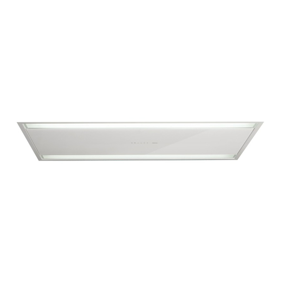
Manuels Connexes pour FALMEC Eclisse 120


Sommaire des Matières pour FALMEC Eclisse 120
- Page 1 LIBRETTO ISTRUZIONI INSTRUCTIONS BOOKLET BEDIENUNGSSANLEITUNG LIVRET D’INSTRUCTIONS Ed. 2014...
- Page 2 Gentile Signora/Signore, congratulazioni! Lei ha acquistato una cappa di prestigio e di sicura qualità. Perché Lei possa ottenere le migliori prestazioni, Le suggeriamo di seguire con attenzione le istruzioni per l’uso e manutenzione che troverà in questo libretto; inoltre, per ordinare i filtri di ricambio al carbone attivo utilizzi l’apposito tagliando che troverà...
- Page 7 A I R A I R 360°...
- Page 8 rinforzo controso tto false ceiling reinforcement Montaggio / Assembly Smontaggio / Disassembly...
- Page 9 FR (optional) 360°...
- Page 10 g. 8 TC SLIM TC SLIM...
- Page 11 g. 9 UM SLIM UM SLIM SM SLIM SM SLIM...
- Page 12 g. 10 so tto ceiling controso tto false ceiling rinforzo controso tto false ceiling reinforcement biadesivo double adhesive so tto ceiling rinforzo controso tto false ceiling reinforcement controso tto false ceiling...
- Page 13 g. 11 g. 12 g. 13 g. 14 g. 15...
- Page 15 LIBRETTO ISTRUZIONI AVVERTENZE È molto importante che questo libretto istruzioni sia conservato insieme all’apparec- chiatura per qualsiasi futura consultazione. Se l’apparecchio dovesse essere venduto o trasferito ad un’altra persona, assicurarsi che il libretto venga fornito assieme, in modo che il nuovo utente possa essere messo al corrente del funzionamento della cappa e delle avvertenze relative.
- Page 16 - Assicurarsi che vi sia una adeguata ventilazione nella stanza se la cappa è utilizzata con altri apparecchi che utilizzano combustibili come gas o altro. - Non accendere fiamme libere sotto la cappa. - Non collegare l’apparecchio a condotti di scarico dei fumi prodotti dalla combustione (cal- daie, caminetti, ecc).
- Page 17 chio dalla rete elettrica. Assicurarsi che non vengano scollegati o tagliati fili elettrici all’interno della cappa; nel caso si verifichino tali situazioni contattare il centro assistenza più vicino. Per l’allacciamento elettrico rivolgersi a personale qualificato. Il collegamento deve essere eseguito in conformità con le disposizioni di legge in vigore. Con- trollare che la valvola limitatrice e l’impianto elettrico possano sopportare il carico dell’apparec- chio (vedere targhetta caratteristiche tecniche al punto B).
- Page 18 FUNZIONAMENTO CONTROLLO ELETTRONICO TASTO 1 Timer: Con il motore in funzione la pressione del tasto attiva lo spegnimento temporizzato del motore dopo 15 minuti. Il tasto 1 lampeggia ad indicare che la funzione è attiva. Al termine dei 15 minuti il motore e la luce si spengono.
- Page 19 TASTO 6 Luce: La pressione breve del tasto T6 accende e spegne la luce. Associazione del radiocomando alla cappa : Con motore e luce spenta, la pressione prolungata del tasto T6 attiva la modalità di associazione del radiocomando. Il Tasto T6 lampeggia per un massimo di 10 secondi. Durante questo periodo è necessario pre- mere almeno un tasto del radiocomando per effettuare l’associazione.
- Page 20 ILLUMINAZIONE MONTAGGIO E SOSTITUZIONE La cappa è dotata di illuminazione con faretti led ad alta efficienza, basso consumo e durata molto elevata in condizioni di normale utilizzo. MANUTENZIONE E PULIZIA Una costante manutenzione garantisce un buon funzionamento ed un buon rendimento nel tempo.
- Page 21 MONTAGGIO CAPPA - Predisporre foro sul contro-soffitto secondo le indicazioni dei disegni presenti all’inizio del libretto. Fissare la dima di ulteriore rinforzo, in dotazione, sulla parte interna non in vista del controsoffitto come illustrato in figura 10. ATTENZIONE IL CONTRO-SOFFITTO DEVE ESSERE OPPORTUNAMENTE RINFORZA- TO PER SORREGGERE IN SICUREZZA LA CAPPA.
- Page 22 Motore remoto posizionato in un vano tecnico protetto dagli agenti atmosferici all’interno dell’abitazione Definire il tipo di uscita: - Uscita rettangolare da 90x220 mm (fig. 6). Rimuovere la flangia FC fissata sulla cappa e montare la flangia per tubo rettangolare FR (optio- nal).
- Page 23 INSTRUCTIONS BOOKLET WARNINGS This instruction booklet must be kept together with the appliance for future refer- ence. If the appliance is sold or consigned to other parties, check that the booklet is supplied with it, to ensure that the new user has the correct information on the operation of the range hood and is aware of the warnings.
- Page 24 Before performing any cleaning or maintenance operations, disconnect the appli- ance by unplugging it or using the main switch. The manufacturer disclaims all li- ability for any damage that may be directly or indirectly caused to people, things and animals due to the failure to follow all the instructions provided in this booklet and above all the warnings relating to the installation, operation and maintenance of the appliance.
- Page 25 that the relief valve and the electrical system are able to support the load of the appliance (see the technical specifications in point B). Some types of appliance are supplied with a cable without plug; in this case, “standardised” plugs must be used, keeping in mind that: - the yellow-green wire must be used for the earth, - the blue wire must be used for the neutral, - the brown wire must be used for the phase;...
- Page 26 KEY 2 1°/OFF: If the motor is stopped, pressing the key lowers the mobile part and activates the motor at the 1st speed: this takes place 20 seconds after the mobile part starts opening (key T2 lights up). If the motor is at the 1st speed, pressing the key makes the motor stop and the LED for key T2 switches off.
- Page 27 ‘ ‘ key: Pressing the key will decrease motor speed. If the 1st speed is active, pressing the key switches the motor off. ‘ ‘ key: If the motor is turned off, pressing the key activates the motor at the 1st speed. If the motor is running, pressing the key increases the motor speed to the maximum speed.
- Page 28 are completely dry before repositioning them. To remove and replace these filters, see the instructions in point H1. This operation should be performed at regular intervals. 2. CARBON FILTERS Hood not set up for carbon filter. 3. CLEANING THE OUTSIDE OF THE APPLIANCE It is advised to clean the external hood surfaces at least every 15 days in order to avoid that oily or greasy substances affect the steel surfaces.
- Page 29 Then remove the central glass panel (G), see fig. 1. To remove the glass, disconnect the elec- tronic pushbutton panel connector. This way you have direct access to the motor unit fastening holes. - Find the type of installation for the extraction version: With the motor unit (UM) fastened to the range hood: 1) Remove the FC flange fitted on the range hood and the FM flange fitted on the UM (fig.
- Page 30 6) Fasten the slim motor (UM SLIM) to the range hood body using the 4 supplied screws. Connect connector (CM) to the hood electronic connector (CE) (fig.13). 7) Remount the filters (MFL), the side glass panels and the central glass panel, reconnecting the connectors relating to the LED strips and to the electronic pushbutton panel, following the procedure described in fig.
- Page 31 BEDIENUNGSANLEITUNG HINWEISE Diese Bedienungsanleitung muss unbedingt zusammen mit dem Gerät aufbewahrt werden, um in Zukunft nachgeschlagen werden zu können. Sollte das Gerät verkauft bzw. einer anderen Person übergeben werden, muss die Bedienungsanleitung unbedingt mitgeliefert werden, damit der neue Benutzer mit dem Betrieb der Dunstabzugshaube und den diesbezüglichen Hinweisen vertraut werden kann.
- Page 32 Inneren der Dunstabzugshaube angegebenen Daten übereinstimmt. Auf keinen Fall unter der Dunstabzugshaube auf “offenem Feuer” kochen. Die Friteusen wäh- rend der Benutzung kontrollieren: das überhitzte Öl könnte sich entzünden. Für eine ausreichende Lüftung im Raum sorgen, wenn die Dunstabzugshaube zusammen mit anderen Geräten, die mit Brennstoffen und ähnlichen Stoffen arbeiten, verwendet wird.
- Page 33 ELEKTRISCHER ANSCHLUSS (Dieser Abschnitt ist Fachpersonal mit der für den Stromanschluss erforderlichen Qualifikation vorbehalten) ACHTUNG! Vor jedem Eingriff im Innern der Haube muss das Gerät vom Stromnetz getrennt werden. Sicherstellen, dass die Stromkabel im Innern der Dunstabzugshau- be nicht abgeklemmt oder durchgeschnitten werden; sollte dies dennoch vorkom- men, den nächst gelegenen Kundendienst kontaktieren.
- Page 34 viert ist. Nach 15 Minuten schalten sich der Motor und die Leuchte aus. Auch wenn die Motorgeschwindigkeit verändert wird, wird die Zählung nicht unterbrochen. Wenn der Motor mit der Taste 2 gestoppt wird, wird die Funktion automatisch abgeschaltet. Wenn die Funktion Timer aktiviert ist, kann sie mit der Taste 1 ausgeschaltet werden. Öffnung des beweglichen Elements (Kundendienst-Modus): Wenn alle Led-Anzeigen der Tastatur ausgeschaltet sind (Leuchte und Motor Off ) ermöglicht der längere Druck der Taste das Senken des beweglichen Teils der Abzugshaube, um die War-...
- Page 35 TASTE 6 Licht: Durch kurzes Drücken der Taste T6, kann das Licht ein- und ausgeschaltet werden. Zuordnung der Funksteuerung zur Abzugshaube: Wenn der Motor und das Licht ausgeschaltet sind, wird durch das lange Drücken der Taste T6 die Modalität für die Zuordnung der Funksteuerung aktiviert. Die Taste T6 blinkt maximal 10 Sekunden lang.
- Page 36 METALLFILTER UND KOHLEFILTER 1. METALLFILTER Um die Metallfilter zu erreichen muss der bewegliche Teil im Kundendienst-Modus (zuvor beschrieben) und Befolgung des nachstehenden Verfahrens gesenkt werden: wenn alle Led-Anzeigen der Tastatur ausgeschaltet sind (Licht und Motor off ), gestattet der verlän- gerte Druck der Taste das Senken des beweglichen Elements der Abzugshaube, um die Wartung durchführen zu können.
- Page 37 Die Verwendung von Scheuermitteln und rauhen Tüchern wird die Oberflächenbehand- lung des Stahls für immer beschädigen. Bei Nichtbeachtung dieser Hinweise wird es zu einer nicht mehr zu beseitigenden Beschä- digung der Stahlfläche kommen. Die vorliegenden Hinweise müssen zusammen mit der Bedienungsanleitung der Dunstabzugshaube aufbewahrt werden.
- Page 38 befestigen (siehe Abb. 4). 3) Die Abzugshaube in der Nähe der Zwischendecke anheben: den Ausgang der Motoreinheit UM mit einem Schlauch an die äußere Abluftleitung anschließen. Den elektrischen Anschluss erst ausführen, nachdem die Stromversorgung der Abzugshaube unterbrochen wurde. Die Sicherheitsketten in die ent- sprechenden Öffnungen im oberen Teil der Abzugshaube einführen (Abb.
- Page 39 Die Abzugshaube elektrisch versorgen und die jeweiligen Funktionsweisen prüfen. LIVRET D’INSTRUCTIONS AVERTISSEMENTS Conserver cette notice avec l’appareil pour pouvoir la consulter en cas de besoin. Si l’appareil est vendu ou cédé à tiers, veiller à ce que la notice soit fournie en même temps pour que le nouvel utilisateur puisse avoir toutes les indications concernant le fonctionnement de la hotte et les avertissements correspondants.
- Page 40 - Ne pas allumer de flammes libres en dessous de la hotte. - Ne pas relier l’appareil aux conduits d’ é vacuation des fumées dues à la combustion (chau- dières, cheminées, etc.). - S’assurer que les normes en vigueur sur l’ é vacuation de l’air à l’ e xtérieur du local sont re- spectées avant d’utiliser la hotte.
- Page 41 S’assurer qu’aucun fil n’est débranché ou coupé ; si c’est le cas, contacter le Service après-vente le plus proche. S’adresser à du personnel qualifié pour le branchement électrique. Les branchements doivent être effectués conformément aux dispositions de loi en vigueur. Vérifier si le disjoncteur et l’installation électrique peuvent supporter la charge de l’appareil (voir plaque des caractéristiques techniques au point B).
- Page 42 FONCTIONNEMENT DU DISPOSITIF DE CONTRÔLE ÉLECTRONIQUE TOUCHE 1 Timer : La pression de la touche avec le moteur en marche active l’arrêt temporisé du moteur après 15 minutes. La touche 1 clignote pour indiquer que la fonction est activée. Arès écoulement des 15 minutes, le moteur et la lumière s’éteignent.
- Page 43 La 4e vitesse est temporisée ; si l’utilisateur sélectionne une autre vitesse, le moteur reste en 4e pendant 7 minutes, puis se met en 3e. La touche T5 s’éteint et la touche T4 s’éclaire. TOUCHE 6 Lumière : La pression brève de la touche T6 allume et éteint la lumière. Association de la radiocommande à...
- Page 44 FILTRES METALLIQUES ET FILTRES A CHARBON 1. FILTRES MÉTALLIQUES Pour accéder aux filtres métalliques, il faut abaisser la partie mobile en modalité assis- tance (décrite précédemment) en respectant la procédure suivante : quand toutes les LED du clavier sont éteintes (lumière et moteur off ), la pression prolongée de la touche permet d’abaisser l’élément mobile de la hotte pour pouvoir effectuer l’entretien.
- Page 45 merce car cela abîmerait irrémédiablement le traitement superficiel de l’inox. La surface définitivement abîmée de l’inox sera la conséquence directe du non-respect de ces indications. La notice complète doit être conservée avec l’appareil. Le fabricant décline toute responsabilité si ces indications ne sont pas respectées. 4.
- Page 46 électrique seulement après avoir désactivé la ligne électrique qui alimente la hotte. Enfiler les chaînes de sécurité sur les trous prédisposés dans la partie supérieure de la hotte (fig. 5). 4) Insérer la hotte dans le faux plafond après l’avoir renforcé. Les crochets G, en s’ouvrant, soutiennent provisoirement la hotte sur le faux plafond.
- Page 48 Note...
- Page 49 Note...
- Page 50 Decreto Legislativo del 30/06/2003 n. 196 - art. 7 Codice in materia di protezione dei dati personali. 1. L’interessato ha diritto di ottenere la conferma dell’ e sistenza o meno di dati personali che lo riguardano, anche se non ancora registrati, e la loro comunicazione in forma intelleggibile.
- Page 51 8, 9 e 10 del citato decreto legislativo; - titolare del trattamento dei dati è Falmec s.p.a. - Via dell’ A rtigianato, 42 - Vittorio Veneto (TV). Il titolare del trattamento...
- Page 52 In caso necessiti intervenire per anomalie di funzionamento, si prega di telefonare alla ditta Falmec indicando i codici sotto riportati, la quale Vi farà pervenire un tecnico per la riparazione (vedere condizioni di garanzia all’interno). CERTIFICATO DI GARANZIA...