Publicité

Les langues disponibles

Les langues disponibles

Liens rapides

Your airless paint sprayer has been engineered and manufactured to our high standard for dependability, ease of operation,
and operator safety. When properly cared for, it will give you years of rugged, trouble-free performance.
WARNING:
To reduce the risk of injury, the user must read and understand the operator's manual before using this
product. If you do not understand the warnings and instructions in the operator's manual, do not use this product.
SAVE THIS MANUAL FOR FUTURE REFERENCE
Cette produit a été conçue et fabriquée conformément aux strictes
normes de fiabilité, simplicité d'emploi et sécurité d'utilisation.
Correctement entretenu, cet outil vous donnera des années de
fonctionnement robuste et sans problème.
AVERTISSEMENT :
blessures, l'utilisateur doit lire et veiller à bien comprendre le
manuel d'utilisation avant d'employer ce produit.
Merci de votre achat.
CONSERVER CE MANUEL POUR
FUTURE RÉFÉRENCE
Pour réduire les risques de
OPERATOR'S MANUAL
MANUEL D'UTILISATION
MANUAL DEL OPERADOR
AIRLESS/FINISH PAINT
SPRAYER
PULVÉRISATEUR À PEINTURE
SANS AIR/FINITION
ROCIADOR DE PINTURA SIN
AIRE/ACABADO
M4910-21
Su producto ha sido diseñado y fabricado de conformidad con
nuestras estrictas normas para brindar fiabilidad, facilidad de
uso y seguridad para el operador. Con el debido cuidado, le
brindará muchos años de sólido funcionamiento y sin problemas.
ADVERTENCIA:
el usuario debe leer y comprender el manual del operador antes
de usar este producto.
Le agradecemos su compra.
GUARDE ESTE MANUAL PARA
FUTURAS CONSULTAS
Para reducir el riesgo de lesiones,

Publicité

Table des Matières
loading

Sommaire des Matières pour Milwaukee M4910-21

  • Page 1 ROCIADOR DE PINTURA SIN AIRE/ACABADO M4910-21 Your airless paint sprayer has been engineered and manufactured to our high standard for dependability, ease of operation, and operator safety. When properly cared for, it will give you years of rugged, trouble-free performance.
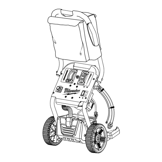
  • Page 2 See this fold-out section for all the figures referenced in the operator’s manual. Voir que cette section d’encart pour toutes les figures a adressé dans le manuel d’utilisation. Vea esta sección de la página desplegable para todas las figuras mencionó en el manual del operador. A - Pump (pompe, bomba) Fig.
  • Page 3 Fig. 3 Fig. 5 Fig. 7 A - Axle (essieu, eje) B - Wheel (roue, rueda) A - Nozzle tip guard (protecteur d’embout, C - Hitch pin (goupille de sûreté, pasador del protección para la punta de la boquilla) enganche) B - Reversible spray tip (embout de pulvérisation réversible, punta de rociado invertible) C - Tip saddle (sellette de embout, punta del...
  • Page 4 Fig. 9 Fig. 11 Fig. 13 EVEN STROKES 10 - 12 in. 10 - 12 po PASSES UNIFORMES 10 - 12 pulg. CORTES PAREJOS A - Orifice size increases (la taille d’orifice augmente, el tamaño del orificio aumenta) B - Fan width decreases (la largeur de ventilateur diminue anchura del ventilador disminuye) Fig.
  • Page 5 Fig. 16 Fig. 18 A - Intake tube (tube d’admission, tubo de entrada) B - Filter (filtre, filtro) Fig. 17 A- Trigger (gâchette, gatillo) B - Lock-off lever (levier de blocage de la gâchette, palanca de seguro de apagado) C - Sprayer handle (poignée de pulvérisateur, mango del rociador) D - Intake tube (tube d’admission, tubo de entrada) E - Filter (filtre, filtro) F - Nut (écrou, tuerca)
  • Page 6: Table Des Matières

    AIRLESS PAINT SPRAYER TWO YEAR LIMITED WARRANTY Your MILWAUKEE airless paint sprayer is warranted to the original purchaser only to be free from defects in material and workmanship. Subject to certain exceptions, MILWAUKEE will repair or replace any part on your MILWAUKEE airless paint sprayer which is defective in material or workmanship for a period of two (2) years after the date of purchase.
  • Page 7: Important Safety Instructions

    IMPORTANT SAFETY INSTRUCTIONS WARNING: To reduce the risk of fire or explosion: WARNING:  Do not spray flammable or combustible materials near SAVE THESE INSTRUCTIONS. To reduce the risks of an open flame or sources of ignition such as cigarettes, fire or explosion, electric shock, and the injury to per- motors, and electrical equipment.
  • Page 8: Specific Safety Rules

    IMPORTANT SAFETY INSTRUCTIONS  Know how to stop the unit and bleed pressure quickly. follow the manufacturer’s instructions for turning off Be thoroughly familiar with the controls. the unit and relieving the pressure before removing the spray tip to clean. WARNING: To reduce the risk of injury: ...
  • Page 9 SPECIFIC SAFETY RULES  WARNING: High pressure spray can be dangerous  Always unplug the paint sprayer, shut the unit off if subject to misuse. The spray must not be directed and release pressure before servicing, cleaning the tip or guard, changing the tip, or leaving unat- at persons, animals, electrical devices, or the machine itself.
  • Page 10: Symbols

    SYMBOLS The following signal words and meanings are intended to explain the levels of risk associated with this product. SYMBOL SIGNAL MEANING Indicates an imminently hazardous situation, which, if not avoided, will result DANGER: in death or serious injury. Indicates a potentially hazardous situation, which, if not avoided, could result WARNING: in death or serious injury.
  • Page 11: Extension Cords

    ELECTRICAL EXTENSION CORDS WARNING: Use only 3-wire extension cords that have 3-prong grounding plugs and 3-pole receptacles that accept the product’s plug. Keep the extension cord clear of the working area. When using a power tool at a considerable distance from Position the cord so that it will not get caught on lumber, the power source, use an extension cord heavy enough to tools, or other obstructions while you are working with a...
  • Page 12: Features

    FEATURES PRODUCT SPECIFICATIONS Flow Rate ............0.31 GPM Input ......... 120 V, AC only, 60 Hz, 15 Amps Fluid Pressure..........800-3,000 PSI Weight ..............41 lbs. Air Pressure ............. 5-8 PSI KNOW YOUR AIRLESS PAINT SPRAYER FINISH SPRAY TECHNOLOGY The two-stage turbine delivers high volume, low pressure See Figure 1.
  • Page 13: Assembly

    ASSEMBLY UNPACKING This product requires assembly. WARNING:  Carefully lift the product from the carton and place on a Do not connect to power supply until assembly is level work surface. complete. Failure to comply could result in accidental starting and possible serious personal injury. WARNING: TOOLS NEEDED Do not use this product if any parts on the Loose Parts...
  • Page 14: Operation

    ASSEMBLY INSTALLING NOZZLE TIP GUARD ON  Insert the desired reversible spray tip into the nozzle tip guard. DUAL-ACTION™ PISTOL-GRIP SPRAYER  Insert metal saddle into the nozzle tip guard. The metal See Figures 6 - 7. saddle should be securely seated on the reversible spray See operator’s instructions for flushing, priming, and cleaning tip.
  • Page 15 OPERATION  Lock the sprayer trigger.  Turn PRIME/SPRAY lever to PRIME. This releases pump pressure.  Turn HI/OFF/FINISH switch OFF.  Push the lock-off lever up to unlock the sprayer trig-  Replace nozzle tip guard and reversible spray tip onto ger and point to inside wall of paint container releasing pistol-grip sprayer.
  • Page 16: Painting Tips

    OPERATION • Make one pass for each stroke. Overlap strokes in WARNING: halves for full coverage.  When finished, return any unused paint or stain to its This is a high pressure device. To reduce the risk of injury, original container and thoroughly clean the sprayer. user must read and understand operator’s manual.
  • Page 17 OPERATION  Unplug the paint sprayer. The paint sprayer will draw cleaning fluid up the intake tube through the pump and out the return tube into the waste  Leave intake tube and return tube in paint. container. Allow the cleaning fluid to run through the system ...
  • Page 18: Maintenance

    MAINTENANCE  Thoroughly clean paint sprayer and DUAL-ACTION ™ WARNING: pistol-grip sprayer following the instructions in Cleaning the Sprayer earlier in this manual. When servicing, use only identical replacement parts.  Be sure that machine and tubes are clear of any water or Use of any other parts may create a hazard or cause fluid, as these may freeze.
  • Page 19: Troubleshooting

    TROUBLESHOOTING PROBLEM CAUSE POSSIBLE SOLUTION Pump does not prime Prime/Spray valve is in Spray position Turn Prime/Spray lever to Prime Inlet screen is clogged or intake tube is not Clean debris off inlet screen and make immersed sure intake tube is at bottom of paint bucket Inlet valve check ball is stuck Press Rapid Valve Release button...
  • Page 20: Garantie

    PULVÉRISATEUR À PEINTURE SANS AIR GARANTIE LIMITÉE DE DEUX ANS Chaque pulvérisateur à peinture sans air MILWAUKEE est garanti à l’acheteur d’origine être exempt de vice du matériau et de fabrication. Sous réserve de certaines exceptions, MILWAUKEE réparera ou remplacera toute pièce d’un pulvérisateur à peinture sans air MILWAUKEE qui se sera avéré...
  • Page 21: Instructions Importantes Concernant La Sécurité

    INSTRUCTIONS IMPORTANTES CONCERNANT LA SÉCURITÉ  Dans le cas des unités uniquement compatibles avec des AVERTISSEMENT : substances à base d’eau ou avec des essences minérale ayant un point d’éclair de 60 °C (140 °F), ne pulvériser aucun liquide CONSERVER CES INSTRUCTIONS. Pour réduire les ayant un point d’éclair inférieur à...
  • Page 22: Règles De Sécurité Particulières

    INSTRUCTIONS IMPORTANTES CONCERNANT LA SÉCURITÉ AVERTISSEMENT :  Ne pas laisser l’unité sans surveillance lorsque celle-ci Pour réduire les risques de blessure : est en marche ou sous pression. Lorsque l’unité n’est pas  Toujours porter une protection oculaire certifiée conforme utilisée, l’éteindre et relâcher la pression conformément aux à...
  • Page 23 RÈGLES DE SÉCURITÉ PARTICULIÈRES  Ne jamais mettre la machine en marche si de la glace s’est substances peuvent être dangereux s’ils sont inhalés ou s’ils entrent en contact avec le corps. formée sur quelque partie que ce soit.  AVERTISSEMENT : Les pulvérisateur à haute pression ...
  • Page 24: Symboles

    SYMBOLES Les termes de mise en garde suivants et leur signification ont pour but d’expliquer le degré de risques associé à l’utilisation de ce produit. SYMBOLE SIGNAL SIGNIFICATION Indique une situation extrêmement dangereuse qui, si elle n’est pas évitée, DANGER : aura pour conséquences des blessures graves ou mortelles.
  • Page 25: Caractéristiques Électriques

    CARACTÉRISTIQUES ÉLECTRIQUES CORDONS PROLONGATEURS AVERTISSEMENT : Utiliser exclusivement des cordons prolongateurs à trois fils doté d’une fiche à prise de terre brabchés sur une prise triphasée Maintenir le cordon prolongateur à l’écart de la zone de compatible avec la fiche de l’outil. Lors de l’utilisation d’un travail.
  • Page 26: Caractéristiques

    CARACTÉRISTIQUES FICHE TECHNIQUE Pression d’air ........20685 kPa (3 000 PSI) Débit ...........0,91 lpm (0,31 GPM) Alimentation ....120 V, c.a. seulement, 60 Hz, 15 A Pression du liquide ............... 55,16 kPa - 20 685 kPa (800-3 000 PSI) Poids ............18,6 kg (41 lb) VEILLEZ À...
  • Page 27: Déballage

    ASSEMBLAGE DÉBALLAGE AVERTISSEMENT : Ce produit doit être assemblé. Ne pas brancher sur le secteur avant d’avoir terminé  Sortir soigneusement la produit du carton et la poser sur un l’assemblage. Le non respect de cet avertissement peut plan de travail horizontal. causer un démarrage accidentel, entraînant des blessures graves.
  • Page 28: Accessoires

    ASSEMBLAGE INSTALLER LE PROTECTEUR D’EMBOUT DE LA  Insérer l’embout de pulvérisation réversible voulu dans le BUSE SUR LE PISTOLET DE PULVÉRISATION protecteur d’embout de la buse.  Insérer la selle de renforcement en métal dans le protecteur DUAL-ACTION ™ d’embout de la buse.
  • Page 29 UTILISATION  Appuyer sur le levier de verrouillage pour verrouiller la détente CHOIX D’UN EMBOUT DE PULVÉRISATION du pulvérisateur. Voir la figure 11.  Laisser le levier « prime/spray » (amorçage/pulvérisation) à la Les embouts de pulvérisation comportent des trous de différentes position «...
  • Page 30: Pulvérisation

    UTILISATION Pour augmenter la durée de vie des embouts de pulvérisation, mouvement. Pour empêcher l’accumulation d’enduit, ne pas recourir à la plus faible pression nécessaire pour appliquer un continuer d’appuyer sur la gâchette entre deux mouvements. • Compléter un passage par mouvement. Chaque mouvement revêtement égal d’enduit.
  • Page 31 UTILISATION  Verrouiller le pistolet de pulvérisation et suivre la Procédure de  Placer l’interrupteur « HIGH / OFF / FINISH » (élevée, arrêt, libération de la pression. finition) à la position « HI » (élevée).  Placer l’interrupteur « HIGH / OFF / FINISH » (élevée, arrêt, La station de peinture achemine le nettoyant liquide dans le tube finition) à...
  • Page 32: Procédures D'entretien

    ENTRETIEN  S’assurer que l’unité et les tubes sont exempts d’eau ou de tout autre liquide, étant donné que les fluides sont AVERTISSEMENT : susceptibles de geler. Utiliser exclusivement des pièces d’origine pour les  Entreposer les tuyaux, le pistolet de pulvérisation, la buse réparations.
  • Page 33: Dépannage

    DÉPANNAGE PROBLÈME CAUSE SOLUTION POSSIBLE Le moteur ne tourne pas La station de peinture n’est pas S’assurer que l’unité est branchée. branchée. L’interrupteur « On/Off » (marche/arrêt) est Régler l’interrupteur « On/Off » (marche/arrêt) réglé à la position « Off » (A<arrêt). à...
  • Page 34 DÉPANNAGE PROBLÈME CAUSE SOLUTION POSSIBLE Le levier « prime/spray » (amorçage/ Le levier « prime/spray » (amorçage/ Communiquer avec un centre de réparations pulvérisation) est réglé à la position pulvérisation) est sale ou endommagé agréé « Spray » (pulvérisation), mais du liquide circule dans le tube d’amorçage Le pistolet de pulvérisation leaks...
  • Page 35 Se garantiza sólo al comprador original de un rociador de pintura sin aire MILWAUKEE que el producto no presenta defectos en material ni mano de obra. En un plazo de dos (2) años a partir de la fecha de compra y sujeto a ciertas excepciones, MILWAUKEE reparará...
  • Page 36: Reglas De Seguridad Generales

    REGLAS DE SEGURIDAD GENERALES ADVERTENCIA: Para reducir el riesgo de estallido o explosión: ADVERTENCIA:  No rocíe materiales inflamables ni combustibles cerca de llamas abiertas o fuentes de ignición, como cigarrillos, motores y GUARDE ESTAS INSTRUCCIONES. Para reducir el equipos eléctricos. riesgo de incendio o explosión, descanga eléctrica, y la ...
  • Page 37: Reglas De Seguridad Específicas

    REGLAS DE SEGURIDAD GENERALES ADVERTENCIA:  No deje la unidad conectada a la corriente ni bajo presión Para reducir el riesgo de lesiones: mientras está desatendida. Cuando no use la unidad, apáguela  Cuando esté pintando, use siempre protección ocular y alivie la presión de conformidad con las instrucciones del adecuada con la marca de cumplimiento de la norma ANSI fabricante.
  • Page 38 REGLAS DE SEGURIDAD ESPECÍFICAS pinturas, los solventes y otros materiales pueden ser dañinos  Nunca dirija un chorro de agua en dirección de personas o animales, ni hacia dispositivos eléctricos. si se inhalan o si entran en contacto con el cuerpo. ...
  • Page 39: Símbolos

    SÍMBOLOS Las siguientes palabras de señalización y sus significados tienen el objeto de explicar los niveles de riesgo relacionados con este producto. SÍMBOLO SEÑAL SIGNIFICADO Indica una situación peligrosa inminente, la cual, si no se evita, causará la muerte PELIGRO: o lesiones serias.
  • Page 40: Cables De Extensión

    ASPECTOS ELÉCTRICOS CABLES DE EXTENSIÓN ADVERTENCIA: Sólo utilice cables de extensión de 3 conductores con clavijas de tres puntas y contactos de tres polos que acepten la clavija Mantenga el cable de extensión fuera del área de trabajo. del cable de la herramienta. Si la herramienta eléctrica debe Al trabajar con una herramienta eléctrica, coloque el cable situarse a una distancia importante de la toma de corriente, de tal manera que no pueda enredarse en la madera,...
  • Page 41: Características

    CARACTERÍSTICAS ESPECIFICACIONES DEL PRODUCTO Caudal ..........0,91 lpm (0,31 GPM) Presión de aire .........20685 kPa (3 000 PSI) Corriente de entrada ..120 V, sólo corr. alt., 60 Hz, 15 A Presión de fluidos ..............55,16 kPa - 20 685 kPa (800-3 000 PSI) Peso .............
  • Page 42: Armado

    ARMADO DESEMPAQUETADO ADVERTENCIA: Este producto requiere armarse.  Extraiga cuidadosamente de la caja la producto y los No conecte la unidad a la toma de corriente antes de terminar accesorios. Asegúrese de que estén presentes todos los de armarla. De lo contrario, la unidad puede ponerse en marcha artículos enumerados en la lista de empaquetado.
  • Page 43: Funcionamiento

    ARMADO INSTALACIÓN DE LA PROTECCIÓN DE LA  Inserte el carro portaherramientas de metal en la protección de la punta de la boquilla. El carro portaherramientas de metal PUNTA DE LA BOQUILLA EN EL ROCIADOR CON debe estar firmemente asentado en la punta del rociador EMPUÑADURA DE PISTOLA DUAL-ACTION ™...
  • Page 44 FUNCIONAMIENTO SELECCIÓN DE UNA PUNTA ROCIADORA  Deje la palanca de cebado/rociado en la posición de CEBADO hasta estar listo para rociar de nuevo. Vea la figura 11. LAVADO DE LA ESTACIÓN DE PINTURA Las puntas de rociado vienen con diversos tamaños de agujero y anchos de abanico.
  • Page 45: Consejos Para Pintar

    FUNCIONAMIENTO • Accione el rociador con empuñadura de pistola en pasadas después de usar entre 56,78 l (15 gal.) y 151,4 l (40 gal.). Cuando rectas horizontales. No sostenga el rociador en ángulo. Esto use materiales a base de aceite, cambie las puntas de rociado genera una cobertura despareja.
  • Page 46 FUNCIONAMIENTO  Coloque la palanca de cebado/rociado en la posición de Los tintes y los materiales a base de aceite no se mantienen durante CEBADO (PRIME). un período prolongado.  Asegure el rociador con empuñadura de pistola y siga el ...
  • Page 47: Mantenimiento General

    MANTENIMIENTO  Si desea, almacene las mangueras, el rociador con ADVERTENCIA: empuñadura de pistola y las puntas en la bolsa de almacenamiento. Al dar servicio a la unidad, sólo utilice piezas de repuesto  Pliegue el mango por la parte frontal de la herramienta. idénticas.
  • Page 48: Corrección De Problemas

    CORRECCIÓN DE PROBLEMAS PROBLEMA CAUSA POSIBLE SOLUCIÓN El motor no funciona La estación de pintura no está enchufada Asegúrese de que la unidad esté enchufada El interruptor de encendido/apagado está en Coloque el interruptor de ENCENDIDO/ la posición de APAGADO APAGADO en la posición de ENCENDIDO La estación de pintura se ha apagado Coloque la perilla de presión alta/baja en la...
  • Page 49 CORRECCIÓN DE PROBLEMAS PROBLEMA CAUSA POSIBLE SOLUCIÓN La palanca de cebado/rociado está La palanca de cebado/rociado está sucia o Comuníquese con un centro de servicio configurada para rociar pero sale pintura dañada autorizado a través del tubo de cebado El rociador con empuñadura de pistola Pulverizador partes internas están gastados Comuníquese con un centro de servicio fugas...
  • Page 50 NOTES / NOTAS 17 — Español...
  • Page 51 NOTES / NOTAS 18 — Español...
  • Page 52 CALIFORNIA PROPOSITION 65 WARNING: This product, and For parts or service, contact your nearest MILWAUKEE factory service center or au- the paints designed to be applied thorized service station. Be sure to provide all relevant information when you call or with this product, may contain visit.

Table des Matières