
Manuels Connexes pour Festo 8062644

Sommaire des Matières pour Festo 8062644
- Page 1 8062644 Packaging station Stations Kurzbeschreibung Getting started Descripción breve Brève description Festo Didactic 8062973 de/en/es/fr 05/2017 R1.1...
- Page 2 Revision level: 05/2017 Author: Markus Schmid Layout: 05/2017 Susanne Durz, Frank Ebel © Festo Didactic SE, Rechbergstraße 3, 73770 Denkendorf, Germany, 2017 +49 711 3467-0 www.festo-didactic.com +49 711 34754-88500 did@festo.com Weitergabe sowie Vervielfältigung dieses Dokuments, Verwertung und Mitteilung seines Inhalts verboten, soweit nicht ausdrücklich gestattet.
-
Page 3: Table Des Matières
Die Station Verpacken _____________________________________________________________ 16 Ansicht der Station ________________________________________________________________ 17 Das Modul 2-Achs-Handling mit Schrittmotor ___________________________________________ 18 Das Modul Band __________________________________________________________________ 21 Das Modul Verpacken ______________________________________________________________ 22 Funktion ________________________________________________________________________ 24 Ablaufbeschreibung _______________________________________________________________ 25 © Festo Didactic 8062973... - Page 4 Ablauf starten ____________________________________________________________________ 28 11.7 Einstellung Modul 2-Achs-Handling mit Schrittmotor ____________________________________ 29 11.8 Einstellung Modul Verpacken _______________________________________________________ 34 Wartung und Pflege _______________________________________________________________ 39 Weitere Informationen und Aktualisierungen __________________________________________ 39 Abbildungen der Warnschilder ______________________________________________________ 39 © Festo Didactic 8062973...
-
Page 5: Allgemeine Voraussetzungen Zum Betreiben Der Geräte
Es dürfen keine Geräte mit Schäden oder Mängeln verwendet werden. – Schadhafte Geräte sind zu sperren und aus dem Labor- oder Unterrichtsraum zu entnehmen. – Beschädigte Verbindungsleitungen, Druckluftschläuche und Hydraulikschläuche stellen ein Sicherheitsrisiko dar und müssen aus dem Labor- oder Unterrichtsraum entfernt werden. © Festo Didactic 8062973... -
Page 6: Gefahrenkategorien
Körperverletzungen führen kann, wenn sie nicht vermieden Vorsicht wird. Hinweis auf mögliche Sachschäden: … weist auf eine möglicherweise gefährliche Situation hin, die zu Sachschäden und Umweltschäden führen kann, wenn sie nicht vermieden Hinweis wird. © Festo Didactic 8062973... -
Page 7: Bestimmungsgemäße Verwendung
Regeln gebaut. Dennoch können bei unsachgemäßer Verwendung Gefahren für Leib und Leben des Benutzers oder Dritter und Beeinträchtigungen der Komponenten entstehen. Das Lernsystem von Festo Didactic ist ausschließlich für die Aus- und Weiterbildung im Bereich Automatisierung und Technik entwickelt und hergestellt. Das Ausbildungsunternehmen und/oder die Ausbildenden hat/haben dafür Sorge zu tragen, dass die Auszubildenden die Sicherheitsvorkehrungen, die... -
Page 8: Für Ihre Sicherheit
Stand der Technik und den anerkannten sicherheitstechnischen Regeln gebaut. Dennoch können bei ihrer Verwendung Gefahren für Leib und Leben des Benutzers oder Dritter bzw. Beeinträchtigungen an der Maschine oder an anderen Sachwerten entstehen. © Festo Didactic 8062973... -
Page 9: Arbeits- Und Sicherheitshinweise
Benutzen Sie zur Betätigung der Grenztaster ein Werkzeug, z. B. einen Schraubendreher. Stellen Sie alle Komponenten so auf, dass das Betätigen von Schaltern und Trenneinrichtungen nicht erschwert wird. Beachten Sie Angaben zur Platzierung der Komponenten. © Festo Didactic 8062973... - Page 10 Einige Geräte haben einen hohen Ableitstrom. Diese Geräte müssen zusätzlich mit einem Schutzleiter geerdet werden. Wenn in den Technischen Daten nicht anders angegeben, besitzt das Gerät keine integrierte Sicherung. Ziehen Sie beim Abbauen der Verbindungsleitungen nur an den Sicherheitssteckern, nicht an den Leitungen. © Festo Didactic 8062973...
- Page 11 Lärm durch ausströmende Druckluft kann schädlich für das Gehör sein. Reduzieren Sie den Lärm durch den Einsatz von Schalldämpfern oder tragen Sie einen Gehörschutz, falls der Lärm sich nicht vermeiden lässt. – Alle Abluftanschlüsse der Komponenten der Gerätesätze sind mit Schalldämpfern versehen. Entfernen Sie diese Schalldämpfer nicht. © Festo Didactic 8062973...
-
Page 12: Technische Daten
4 A gesamt Elektrischer Anschluss 2 x 24-polige IEEE-488 Buchse (SysLink) Pneumatischer Anschluss Kunststoffschlauch mit 6 mm Außendurchmesser Druckluftverbrauch bei 600 kPa (Dauerzyklus) 10 l/min Maße 350 mm x 700 mm x 230 mm Änderungen vorbehalten © Festo Didactic 8062973... -
Page 13: Kontaktbelegungstabelle
24 V Versorgung der Eingänge GND A braun-rosa 0V Versorgung der Ausgänge GND A lila 0V Versorgung der Ausgänge GND B 23+24 weiß-blau 0V Versorgung der Eingänge Hinweis Bei allen Vorzugsvarianten SPS sind Kabelbrücken von NOT-AUS auf Bit 1.5 gesteckt. © Festo Didactic 8062973... - Page 14 0 V Versorgung der Ausgänge GND A lila 0 V Versorgung der Ausgänge GND B 23+24 weiß-blau 0 V Versorgung der Eingänge Hinweis Bei allen Vorzugsvarianten SPS sind Kabelbrücken von NOT-AUS auf Bit 1.5 gesteckt. © Festo Didactic 8062973...
-
Page 15: Transport/Auspacken/Lieferumfang
Die Transportbox darf ausschließlich mit geeigneten Hubwagen oder Gabelstaplern transportiert werden. Die Transportbox muss gegen Umfallen und Herunterfallen gesichert sein. Transportschäden sind unverzüglich dem Spediteur und Festo Didactic zu melden. 7.2 Auspacken Beim Auspacken der Station das Füllmaterial der Transportbox vorsichtig entfernen. Beim Auspacken der Station darauf achten, dass keine Aufbauten der Station beschädigt werden. -
Page 16: Aufbau
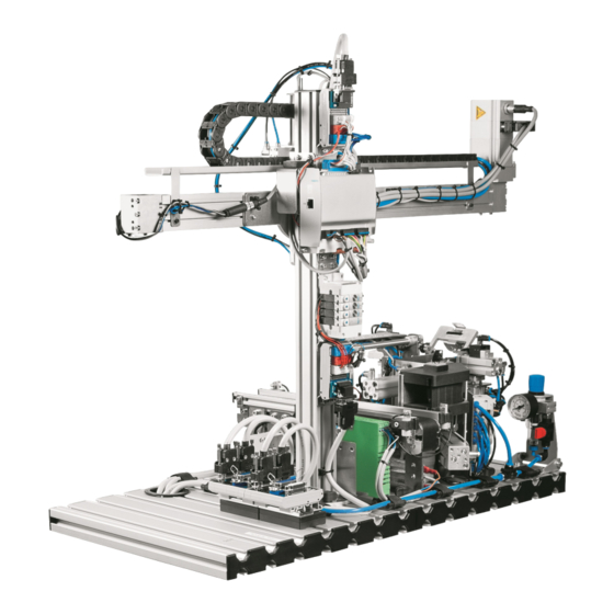
Die Station Verpacken ist aus den Modulen Band, 2-Achs-Handling mit Schrittmotor und Verpacken ® aufgebaut. Die Kombination dieser Module ermöglicht es, ein MPS -Werkstück vollautomatisch zu transportieren und zu verpacken. Die Aufgabe der Station Verpacken ist es Werkstücke vollautomatisch zu verpacken © Festo Didactic 8062973... -
Page 17: Ansicht Der Station
Die Faltkartons stehen in 2 Größen zur Verfügung: • Karton Größe 1 (L x B x H): 48 mm x 42 mm x 50 mm • Karton Größe 2 (L x B x H): 48 mm x 42 mm x 60 mm © Festo Didactic 8062973... -
Page 18: Das Modul 2-Achs-Handling Mit Schrittmotor
Positionen anfahren. Diese Positionen sind die obere und die untere Endlage sowie eine Mittelstellung. In der Mittelstellung können die gepackten Kartons mit dem Greifer gegriffen werden. Die Positionierung der Mittelstellung erfolgt durch einen pneumatisch betätigten Anschlag. Die Werkstücke und die Kartons werden mit einem pneumatischen Parallelgreifer gehandhabt. © Festo Didactic 8062973... - Page 19 Über das untere Mini-I/O-Terminal (13) erfolgt der Datenaustausch der SPS der Station mit der pneumatischen Z-Achse. Die Ventilinsel wird angesteuert, um die Bewegungen der Z-Achse zu steuern und den Greifer zu öffnen oder zu schließen. Gleichzeitig können die Positionen der Z-Achse abgefragt werden. © Festo Didactic 8062973...
- Page 20 3 Positionen eingestellt. Die Positionen können über einen Bit Code angefahren werden. Das Bit 0,0 ist für die Referenzfahrt reserviert. Teachen der Positionen Das Modul 2-Achs-Handling mit Schrittmotor wird mit der FCT-Software angesteuert. Welche Schritte zum Teachen notwendig sind, wird in Kapitel Inbetriebnahme dargestellt. © Festo Didactic 8062973...
-
Page 21: Das Modul Band
Die Endlagen werden mit induktiven Näherungsschaltern nachgewiesen. Erforderliche Modifikationen am Modul Band Folgende Komponenten entfallen: Weiche elektrisch Folgende Komponenten wurden hinzugefügt: Modul pneumatischer Stopper Das Modul Band kann nur in eine Richtung fahren. © Festo Didactic 8062973... -
Page 22: Das Modul Verpacken
Zuführzylinder nicht ausfahren. Der Magazinzylinder hat eine verdrehgesicherte Kolbenstange. Durch einen Näherungsschalter wird die vordere Endlage des Magazinzylinders abgefragt. Dieser Näherungsschalter liefert ein Signal, wenn sich nur noch ein Karton im Magazin befindet. © Festo Didactic 8062973... - Page 23 Die Ausgangsstellung des Antriebs (Magazinschieber in der Führung) wird durch einen Näherungsschalter abgefragt. Der Aufrichtzylinder ist durch 2 Rundzylinder, die eine gemeinsame Abluftdrosselung haben, umgesetzt. Durch einen Näherungsschalter wird die Ausgangsstellung (hinteren Endlage) abgefragt. Der Arretierzylinder ist ein doppeltwirkender Mini-Antrieb. Die Endlagen werden nicht überwacht. © Festo Didactic 8062973...
-
Page 24: Funktion
2-Achs-Handling mit Schrittmotor in den Karton platziert. Jetzt wird der Karton durch den Faltmechanismus geschlossen und durch das Modul 2-Achs-Handling mit Schrittmotor zum Modul Band zurücktransportiert. Auf dem Modul Band wird das verpackte Werkstück zum Bandende transportiert. © Festo Didactic 8062973... -
Page 25: Ablaufbeschreibung
3. Wenn der Karton bereit steht, wird das Werkstück mit den 2 Achs Handling gegriffen und zum Modul Verpacken transportiert. 4. Nachdem der Karton beladen wurde, wird der Karton verschlossen und anschließend zum Modul Band zurückbefördert. 5. Das Modul Band transportiert den Karton zum Bandende oder zu einer Folgestation. © Festo Didactic 8062973... -
Page 26: Inbetriebnahme
SPS Board mit 24 digitalen Ein- und Ausgängen ein Netzgerät 24 V DC, 4,5 A eine Druckluftversorgung mit 600 kPa (6 bar) einen PC mit installierter SPS Programmiersoftware und FCT-Software drei E/A-Kabel (SysLink) © Festo Didactic 8062973... -
Page 27: Montage Von Profilplatte Und Bedienpult
Buchse B durch ein SysLink Kabel mit der SysLink Buchse des Bedienpults. SPS Board – Netzgerät Stecken Sie die 4 mm Sicherheitsstecker in die Buchsen des Netzgerätes. PC – SPS Verbinden Sie Ihren PC durch ein Programmierkabel mit der SPS. © Festo Didactic 8062973... -
Page 28: Spannungsversorgung
Gehen Sie zum Laden der SPS Programme so vor, wie es in den Benutzerhandbüchern der von Ihnen verwendeten Programmiersoftware beschrieben ist. Aktuelle SPS Programme für verschiedene Steuerungen finden Sie im Internet unter folgender Adresse: www.festo-didactic.com > Service > MPS® Mechatronische Systeme > Stationen 11.6 Ablauf starten 1. Überprüfen Sie Spannungsversorgung und Druckluftversorgung. - Page 29 Ändern der Parameter des Motorcontrollers ist durch ein Passwort geschützt, um nicht gewollte Änderungen zu verhindern. Sollte an den Parametern etwas geändert werden, ist dies auf eigene Gefahr durchzuführen. Davor ist unbedingt die Betriebsanleitung der Festo AG & Co. KG zu lesen. Kennwort: Caution_Hazard 1.
- Page 30 Projektnamen ein. Zum Bestätigen klicken Sie auf „Ok“. Das folgende Fenster wird geöffnet. 4. Wählen Sie in diesem Fenster den Motorcontroller CMMO-ST aus und geben Sie dem Motorcontroller einen Namen. Bestätigen Sie die Eingabe mit „OK“. © Festo Didactic 8062973...
- Page 31 Kennwort: Caution_Hazard 6. Bestätigen Sie die Eingabe mit „OK“. Daraufhin öffnet sich ein neues Fenster. Hier können nun die aktuellen Daten des Motorcontrollers auf den jeweiligen PC übertragen werden. Klicken Sie hierzu auf die Schaltfläche „Upload“. © Festo Didactic 8062973...
- Page 32 Das Starten erfolgt durch die FCT Software. Wählen Sie hierzu den Reiter „Referenzfahrt“, um in diesen Modus umzuschalten. Markieren Sie die beiden Felder „FCT“ und „Freigabe“ gesetzt. Achtung Der Antrieb wird jetzt geregelt. Durch Klicken der Schaltfläche „Referenzfahrt“ wird die Referenzfahrt gestartet. Der Antrieb ist nun referenziert und kann eingestellt werden. © Festo Didactic 8062973...
- Page 33 2-Achs-Handling mit Schrittmotor befindet, die Z-Achse entriegelt werden. Sie können die Z-Achse dann von Hand bewegen. Achtung – Kollisionsgefahr Nach Abschluss der Einstellung der Positionen muss die Z-Achse von Hand in die obere Endlage gehoben werden. Das Absperrventil muss geöffnet werden, um die Z-Achse zu verriegeln. © Festo Didactic 8062973...
-
Page 34: Einstellung Modul Verpacken
Magazin eingelegt werden. Betätigen Sie den Magazinschalter und spannen Sie damit den Spannzylinder. Überprüfen sie den Spanndruck. Fahren Sie den Zuführzylinder mit Hilfe der Handhilfsbetätigung aus, um einen Karton zu vereinzeln und aufzufalten. © Festo Didactic 8062973... - Page 35 Halterung gelöst. Dann wird der Aufrichtzylinder von Hand ausgefahren, um zu kontrollieren, ob das Andrücken des Kartondeckels an die Verschlussklappe des Faltmechanismus erfolgt. Sollte zusätzlich die Höhe des Aufrichtzylinders verstellt werden muss, befinden sich die Schrauben auf der Rückseite des Haltewinkels © Festo Didactic 8062973...
- Page 36 Falten Sie jetzt die Einstecklasche des Kartondeckels, indem der Arretierzylinder im ausgefahrenen Zustand leicht auf die Einstecklasche drückt. Drehen Sie die Schrauben wieder fest. Der Aufrichtzylinder ist wieder in der Ausgangsstellung. Beginnen Sie, den Faltmechanismus einzustellen. © Festo Didactic 8062973...
- Page 37 Diese Position kann an der Frontseite des Blechwinkels durch die Langlöcher eingestellt werden. Für den zweiten Falt- und Klappzylinder auf der gegenüberliegenden Seite gilt die gleiche Vorgehensweise. Die beiden Staublaschen des Karton sind geschlossen. © Festo Didactic 8062973...
- Page 38 Jetzt wird die Verschlussklappe des Faltmechanismus von Hand geschlossen. Achten Sie darauf, dass der Karton beim Schließvorgang nicht verklemmt oder gequetscht wird. Prüfen Sie, ob die Einstecklasche des Kartondeckels sauber in den Karton passt. Der Karton ist komplett geschlossen. © Festo Didactic 8062973...
-
Page 39: Wartung Und Pflege
Weiter Informationen und Aktualisierungen zur Technischen Dokumentation der MPS Stationen finden Sie im Internet unter der Adresse: www.festo-didactic.com > Service > MPS® Mechatronische Systeme 14 Abbildungen der Warnschilder Warnschild: Warnung vor einer Gefahr Warnschild: Warnung vor heißer Oberfläche © Festo Didactic 8062973... - Page 40 Station Verpacken © Festo Didactic 8062973...
- Page 41 View of the station ________________________________________________________________ 55 Views of the cardboard box _________________________________________________________ 55 2-axis handling module with stepper motor ____________________________________________ 56 The conveyor module ______________________________________________________________ 59 The packaging module _____________________________________________________________ 60 Function ________________________________________________________________________ 62 Sequence description _____________________________________________________________ 63 © Festo Didactic 8062973...
- Page 42 Teaching position in to the 2-axis handling module with stepper motor _____________________ 67 11.8 Adjusting the packaging module _____________________________________________________ 72 Maintenance and care _____________________________________________________________ 77 Further information and updates ____________________________________________________ 77 Illustrations of warnings ___________________________________________________________ 77 © Festo Didactic 8062973...
-
Page 43: General Prerequisites For Operating The Devices
Damaged devices must be banned from further use and removed from the laboratory or classroom. – Damaged connecting cables, pneumatic tubing and hydraulic hoses represent a safety risk and must be removed from the laboratory or classroom. © Festo Didactic 8062973... -
Page 44: Danger Categories
Indicates a possibly hazardous situation which may result in moderate or slight personal injury if not avoided. Caution Reference to possible property damage: Indicates a possibly hazardous situation which may result in property damage and damage to the environment if not avoided. Note © Festo Didactic 8062973... -
Page 45: Use For Intended Purpose
However, life and limb of the user and third parties may be endangered and the components may be impaired if they are used incorrectly. The learning system from Festo Didactic has been developed and produced exclusively for basic and further training in the field of automation technology. The training company and/or trainers must ensure that all trainees observe the safety precautions described in this workbook. -
Page 46: For Your Safety
However, life and limb of the user and third parties may be endangered and the machine or other property may be damaged during its use. © Festo Didactic 8062973... -
Page 47: Work And Safety Instructions
Risk of injury during troubleshooting! Use a tool such as a screwdriver to actuate limit switches. Set all components up so that it is easy to activate the switches and interrupters. Follow the instructions about positioning the components. © Festo Didactic 8062973... - Page 48 The device is not equipped with an integrated fuse unless specified otherwise in the technical data. Always pull on the plug when disconnecting connecting cables – never pull the cable. © Festo Didactic 8062973...
- Page 49 Noise caused by escaping compressed air may damage your hearing. Reduce noise by using silencers, or wear hearing protection if noise cannot be avoided. – All of the exhaust ports for the components included in the equipment set are equipped with silencers. Do not remove these silencers. © Festo Didactic 8062973...
-
Page 50: Technical Data
Electrical connection Two 24-pin IEEE-488 sockets (SysLink) Pneumatic connection Plastic tubing with 6 mm outside diameter Compressed air consumption at 600 kPa (continuous cycle) 10 l/min. Dimensions 350 x 700 x 230 mm Subject to change © Festo Didactic 8062973... -
Page 51: Pin Allocation Table
0 V supply power for outputs GND A Purple 0 V supply power for outputs GND B 23+24 White-blue 0 V supply power for inputs Note Cable jumpers are connected from emergency off to bit 1.5 on all preferred PLC versions. © Festo Didactic 8062973... - Page 52 0 V supply power for outputs GND A Purple 0 V supply power for outputs GND B 23+24 White-blue 0 V supply power for inputs Note Cable jumpers are connected from emergency off to bit 1.5 on all preferred PLC versions. © Festo Didactic 8062973...
-
Page 53: Transport, Unpacking, Delivery
Examine the station for possible damage after unpacking. The freight forwarder and Festo Didactic must be notified of any damage without delay. 7.3 Delivery Check delivered items against the delivery note and the purchase order. Festo Didactic must be notified of any discrepancies without delay. © Festo Didactic 8062973... -
Page 54: Design
The packaging station consists of a conveyor module, a 2-axis handling module with stepper motor and a ® packaging module. Combining these modules makes it possible to transport and package an MPS workpiece in a fully automated manner. The task of the packaging station is: Fully automated packaging of workpieces © Festo Didactic 8062973... -
Page 55: View Of The Station
Cardboard boxes are available in 2 sizes: • Box size 1 (L x W x H): 48 x 42 x 50 mm • Box size 2 (L x W x H): 48 x 42 x 60 mm © Festo Didactic 8062973... -
Page 56: 2-Axis Handling Module With Stepper Motor
In the mid-position, the packed boxes can be grasped by the gripper. The mid-position is determined by a pneumatically actuated stop. The workpieces and the boxes are handled by a pneumatic parallel gripper. © Festo Didactic 8062973... - Page 57 Data exchange between the station’s PLC and the pneumatic Z-axis is implemented via the lower mini I/O terminal (13). The valve terminal is actuated in order to control Z-axis motion and to open or close the gripper. At the same time, Z-axis positions can be queried. © Festo Didactic 8062973...
- Page 58 Travel to these positions is made possible by means of bit codes. Bit 0.0 is reserved for homing. Teaching the positions in The 2-axis handling module with stepper motor is controlled with FCT software. The steps required for teach-in are described in chapter 11, “Commissioning”. © Festo Didactic 8062973...
-
Page 59: The Conveyor Module
Required modifications of the conveyor module The following components are omitted: Electric deflector The following components have been added: Pneumatic stopper module The conveyor module can only run in one direction. © Festo Didactic 8062973... -
Page 60: The Packaging Module
The magazine cylinder has a non-rotating piston rod. The advanced end position of the magazine cylinder is monitored by a proximity sensor. This proximity sensor generates a signal when only one box remains in the magazine. © Festo Didactic 8062973... - Page 61 The setup cylinder is implemented by means of 2 round cylinder’s which share common exhaust air flow control. The initial position (retracted end position) is monitored by a proximity sensor. The lock cylinder is a double-acting miniature drive. Its end positions are not monitored. © Festo Didactic 8062973...
-
Page 62: Function
2-axis handling module with stepper motor. The box is then closed by the folding mechanism and is returned to the conveyor module by the 2-axis handling module with stepper motor. The conveyor module transports the workpiece to the end of the conveyor belt. © Festo Didactic 8062973... -
Page 63: Sequence Description
4. After the box has been loaded, it’s closed and returned to the conveyor module. 5. The conveyor module transports the box to the end of the conveyor belt or to a downstream station. © Festo Didactic 8062973... -
Page 64: Commissioning
A PLC board with 24 digital inputs and outputs A power pack: 24 V DC, 4.5 A Compressed air supply: 600 kPa (6 bar) A PC with installed PLC programming software and FCT software Three I/O cables (SysLink) © Festo Didactic 8062973... -
Page 65: Mounting The Profile Plate And The Control Console
B to the SysLink socket on the control console. PLC board to power pack Insert the 4 mm safety plugs into the sockets on the power pack. PC to PLC Connect your PC to the PLC via a programming cable. © Festo Didactic 8062973... -
Page 66: Power Supply
Current PLC programs for various controllers can be found on the Internet at the following website: www.festo-didactic.com > Services > MPS® The Modular Production System > Stations 11.6 Starting the sequence 1. Check power supply and compressed air supply. -
Page 67: Teaching Position In To The 2-Axis Handling Module With Stepper Motor
If the parameters need to be changed, the user does so at his or her own risk. It’s important to read the operating instructions issued by Festo AG & Co. KG before changing the parameters. - Page 68 3. A window appears after clicking the “New project” button. Enter a project name to this window. Clock “OK” in order to acknowledge your entry. The following window then appears. 4. Select the CMMO-ST motor controller in this window and assign a name to it. Acknowledge your entry by clicking “OK”. © Festo Didactic 8062973...
- Page 69 6. Acknowledge your entry by clicking “OK”, after which a new window appears. The motor controller’s current data can be transferred to the respective PC with the help of this window. Click the “Upload” button to this end. © Festo Didactic 8062973...
- Page 70 Homing is started with FCT software. Select the “Homing” tab in order to switch to the respective mode. Mark the “FCT” and “Enable” fields as activated. Caution The drive is now controlled. Homing is started by clicking the “Homing” button. The drive is now homed and can be set up. © Festo Didactic 8062973...
- Page 71 Caution – risk of collision After the position settings have been completed, the Z-axis must be lifted manually to its upper end position. The shut-off valve has to be opened in order to lock the Z-axis. © Festo Didactic 8062973...
-
Page 72: Adjusting The Packaging Module
Turn the magazine switch in order to activate the clamping cylinder. Check clamping pressure. Advance the feed cylinder with the help of manual override, in order to separate a box and open it open. © Festo Didactic 8062973... - Page 73 If the height of the setup cylinder also needs to be adjusted, corresponding screws are located on the back of the mounting bracket. © Festo Didactic 8062973...
- Page 74 Fold the box top’s tuck flap by allowing the lock cylinder to press gently against the tuck flap in the advanced position. Retighten the screws. The setup cylinder is once again in its initial position. Start adjusting the folding mechanism. © Festo Didactic 8062973...
- Page 75 This position can be adjusted at the front of the sheet metal bracket with the help of the two oblong holes. The same procedure applies to the second folding/flap cylinder on the other side. Both of the box’s dust flaps are now closed. © Festo Didactic 8062973...
- Page 76 Make sure that the box is not wedged or squeezed during the closing operation. Make sure that the box top’s tuck flap is accurately inserted into the box. The box is now completely closed. © Festo Didactic 8062973...
-
Page 77: Maintenance And Care
Further information and updates for technical documentation for MPS stations are available on the following website: www.festo-didactic.com > Services > MPS® The Modular Production System 14 Illustrations of warnings Warning concerning a hazard Warning concerning hot surfaces © Festo Didactic 8062973... - Page 78 Packaging station © Festo Didactic 8062973...
- Page 79 Esquemas de la caja plegable _______________________________________________________ 93 El módulo Manipulación de dos ejes con motor paso a paso ______________________________ 94 Módulo cinta de transporte _________________________________________________________ 97 El módulo de Embalaje _____________________________________________________________ 98 Funcionamiento _________________________________________________________________ 100 Descripción del proceso __________________________________________________________ 101 © Festo Didactic 8062973...
- Page 80 Memorización de posiciones en el módulo de Manipulación de dos ejes con motor paso a paso ____________________________________________________________ 105 11.8 Ajuste del módulo de Embalaje _____________________________________________________ 110 Cuidados y mantenimiento ________________________________________________________ 115 Informaciones complementarias y actualizaciones ____________________________________ 115 mágenes de los carteles de advertencia _____________________________________________ 115 © Festo Didactic 8062973...
-
Page 81: Condiciones Generales Para El Uso De Los Equipos
– Los aparatos defectuosos deberán inhabilitarse y retirarse de la zona de trabajo. – Los cables, los tubos flexibles y los tubos flexibles hidráulicos dañados representan un peligro y deben retirarse del laboratorio o del aula. © Festo Didactic 8062973... -
Page 82: Categorías De Riesgo
Atención Indicaciones que se refieren a posibles daños materiales: ... indica que existe un posible peligro, que puede causar daños materiales y ecológicos si no se adoptan las medidas necesarias para Nota evitarlo. © Festo Didactic 8062973... -
Page 83: Uso Previsto
Festo Didactic haya ocasionado dichos daños premeditadamente o con extrema negligencia. -
Page 84: Indicaciones De Seguridad
A pesar de ello, su utilización puede generar peligros que podrían afectar la integridad física o poner en peligro la vida de los usuarios o de terceros, así como también provocar daños en la máquina u otros daños materiales. © Festo Didactic 8062973... -
Page 85: Indicaciones De Seguridad Y Utilización
Para accionar los sensores de final de carrera, utilice una herramienta, por ejemplo un destornillador. Efectúe el montaje de todos los componentes de tal manera que pueda acceder fácilmente a los interruptores y a las conexiones. Respete las indicaciones sobre el posicionamiento de los componentes. © Festo Didactic 8062973... - Page 86 Si no se indica lo contrario en los datos técnicos, el aparato no contiene un fusible integrado. Al desconectar los cables, tire únicamente de los conectores de seguridad, nunca de los cables. © Festo Didactic 8062973...
- Page 87 Reduzca el nivel de ruidos Utilizando silenciadores, o bien tapones para los oídos si no fuese posible evitar los ruidos. – Todas las conexiones de escape de aire deberán estar provistas de silenciadores. No retire esos silenciadores. © Festo Didactic 8062973...
-
Page 88: Especificaciones Técnicas Generales
Tubo flexible de material sintético de diámetro exterior de 6 mm Consumo de aire comprimido con 600 kPa (ciclo continuo) 10 l/min Dimensiones 350 mm x 700 mm x 230 mm Reservado el derecho de modificación © Festo Didactic 8062973... -
Page 89: Tabla De Ocupación De Contactos
Alimentación de 0 V en las salidas GND B 23+24 Blanco y azul Alimentación de 0 V en las entradas Nota En todas las variantes de PLC, los cables que puentean la parada de emergencia están conectados al bit 1.5. © Festo Didactic 8062973... - Page 90 Alimentación de 0 V en las salidas GND B 23+24 Blanco y azul Alimentación de 0 V en las entradas Nota En todas las variantes de PLC, los cables que puentean la parada de emergencia están conectados a bit 1.5. © Festo Didactic 8062973...
-
Page 91: Transporte / Desembalaje / Dotación Del Suministro
La caja deberá moverse únicamente utilizando una carretilla elevadora apropiada. La caja deberá estar asegurada de tal manera que no pueda caerse. Cualquier daño ocurrido durante el transporte deberá notificarse de inmediato al transportista y a Festo Didactic. 7.2 Desembalaje Para sacar la estación de su caja de transporte, deberá... -
Page 92: Estructura
La estación Embalaje consta de los módulos Cinta, Manipulación de dos ejes con motor paso a paso y ® Embalaje. La combinación de estos módulos permite transportar y embalar piezas MPS de forma totalmente automática. La tarea de las estaciones de Embalaje es el embalaje totalmente automático de piezas © Festo Didactic 8062973... -
Page 93: Esquema De La Estación
Caja de cartón de tamaño 1 (L x An x Al): 48 mm x 42 mm x 50 mm • Caja de cartón de tamaño 2 (L x An x Al): 48 mm x 42 mm x 60 mm © Festo Didactic 8062973... -
Page 94: El Módulo Manipulación De Dos Ejes Con Motor Paso A Paso
En la posición central se pueden coger las cajas de cartón llenas con la pinza. El posicionamiento a la posición central se lleva a cabo mediante un tope de accionamiento neumático. Las piezas y las cajas de cartón se manipulan con una pinza paralela neumática. © Festo Didactic 8062973... - Page 95 A través del terminal mini I/O inferior (13) se realiza el intercambio de datos del PLC de la estación con el eje neumático Z. Se activa el terminal de válvulas para controlar los movimientos del eje Z y para abrir o cerrar la pinza. De forma simultánea, se pueden consultar las posiciones del eje Z. © Festo Didactic 8062973...
- Page 96 El bit 0,0 está reservado para el recorrido de referencia. Memorización de las posiciones El módulo Manipulación de dos ejes con motor paso a paso se activa mediante el software FCT. Los pasos necesarios para la memorización se explican en el capítulo Puesta en marcha. © Festo Didactic 8062973...
-
Page 97: Módulo Cinta De Transporte
Modificaciones necesarias en el módulo de la cinta transportadora Se prescinde de los siguientes componentes: Bifurcación eléctrica Se han añadido los siguientes componentes: Módulo de freno neumático El módulo de la cinta transportadora solo debe avanzar en un solo sentido. © Festo Didactic 8062973... -
Page 98: El Módulo De Embalaje
El cilindro del cargador cuenta con un vástago antigiro. Mediante un sensor de proximidad se consulta la posición delantera de final de carrera del cilindro del cargador. Este sensor de proximidad emite una señal en el momento en el que solo quede una caja de cartón en el cargador. © Festo Didactic 8062973... - Page 99 El cilindro de ajuste se compone de 2 cilindros redondos con una estrangulación de escape conjunta. Mediante un sensor de proximidad se consulta la posición inicial (posición trasera de final de carrera). El cilindro de retención es un mini accionamiento de doble efecto. Las posiciones finales no se supervisan. © Festo Didactic 8062973...
-
Page 100: Funcionamiento
Entonces, se cierra la caja de cartón mediante el mecanismo de plegado y el módulo de Manipulación de dos ejes con motor paso a paso la vuelve a transportar al módulo de Cinta. El módulo de Cinta transporta la pieza embalada al final de la cinta. © Festo Didactic 8062973... -
Page 101: Descripción Del Proceso
4. Una vez se ha cargado la caja de cartón, se cierra la caja y se devuelve al módulo de Cinta. 5. El módulo de Cinta transporta la caja de cartón al final de la cinta o a la estación siguiente. © Festo Didactic 8062973... -
Page 102: Puesta En Marcha
Una unidad de alimentación de 24 V DC, 4,5 A Una alimentación de aire comprimido con 600 kPa (6 bar) Un PC con software de programación PLC y software FCT instalados Tres cables I/O (SysLink) © Festo Didactic 8062973... -
Page 103: Montaje De La Placa Perfilada Y Del Panel De Mando
Placa PLC – Unidad de alimentación eléctrica Conecte los conectores de seguridad de 4 mm a los conectores de la unidad de alimentación. PC – PLC Conecte el PC al PLC mediante un cable de programación. © Festo Didactic 8062973... -
Page 104: Alimentación De Tensión
En la dirección Internet que se indica a continuación encontrará programas de PLC actuales para diversos tipos de unidades de control: www.festo-didactic.com > Asistencia técnica> MPS® Sistemas mecatrónicos > Estaciones 11.6 Inicio de la secuencia 1. Compruebe la alimentación y el consumo de aire comprimido. -
Page 105: Memorización De Posiciones En El Módulo De Manipulación De Dos Ejes Con Motor Paso A Paso
Si se realiza una modificación en los parámetros, la persona en cuestión lo hace bajo su propia responsabilidad. Antes de ello, es esencial leerse el manual de instrucciones de Festo AG & Co. KG. Contraseña: Caution_Hazard 1. Establezca la conexión al controlador. - Page 106 3. Si hace clic sobre el botón "Nuevo proyecto", se abre una ventana. Introduzca el nombre de proyecto en la ventana. Confirme mediante "Ok". Se abrirá la siguiente ventana. 4. En esta ventana debe seleccionar el controlador de motor CMMO-ST y debe asignarle un nombre al controlador. Confirme la introducción con “OK”. © Festo Didactic 8062973...
- Page 107 Aquí introducir la contraseña. Debe distinguir entre mayúsculas y minúsculas. Contraseña: Caution_Hazard 6. Confirme la introducción con “OK”. Se abrirá una nueva ventana. Aquí podrá transmitir los datos actuales del controlador de motor al ordenador en cuestión. Para ello, haga clic en el botón "Upload". © Festo Didactic 8062973...
- Page 108 Marque los campos "FCT" y "Habilitación". Atención Ahora se regula el accionamiento. Si hace clic sobre el botón "Recorrido de referencia" se inicia el recorrido de referencia. Ahora el accionamiento está referenciado y se puede ajustar. © Festo Didactic 8062973...
- Page 109 Entonces podrá desplazar el eje Z a mano. Atención: peligro de colisión Una vez finalizado el ajuste de las posiciones, es necesario elevar el eje Z manualmente a la posición final superior. Debe abrir la válvula de cierre para bloquear el eje Z. © Festo Didactic 8062973...
-
Page 110: Ajuste Del Módulo De Embalaje
Accione el interruptor del cargador y tense el cilindro de sujeción. Compruebe la presión de sujeción. Extienda el cilindro de alimentación mediante el accionamiento manual auxiliar para separar y desplegar una caja de cartón. © Festo Didactic 8062973... - Page 111 Si además necesita ajustar la altura del cilindro de ajuste, los tornillos se encuentran en la parte trasera de la escuadra de fijación. © Festo Didactic 8062973...
- Page 112 Vuelva a apretar los tornillos. El cilindro de ajuste vuelve a estar en la posición inicial. Comience con el ajuste del mecanismo de plegado. © Festo Didactic 8062973...
- Page 113 ángulo de la plancha de chapa mediante los taladros colisos. Debe proceder de la misma forma con el segundo cilindro de plegado del lado opuesto. Ambas lengüetas de cierre de la caja de cartón están cerradas. © Festo Didactic 8062973...
- Page 114 Asegúrese de que durante el proceso de cierre no se atrape o aplaste la caja de cartón. Compruebe si la lengüeta de inserción se introduce en la caja de cartón de manera limpia. La caja de cartón está completamente cerrada. © Festo Didactic 8062973...
-
Page 115: Cuidados Y Mantenimiento
En la dirección Internet que se indica a continuación se ofrecen informaciones complementarias y actualizaciones de la documentación técnica de las estaciones MPS www.festo-didactic.com > Asistencia técnica> MPS® Sistemas mecatrónicos 14 Imágenes de los carteles de advertencia Cartel: Advertencia ante un peligro Cartel: Advertencia de superficie caliente ©... - Page 116 Estación de Embalaje © Festo Didactic 8062973...
- Page 117 Vues de la boîte pliante ___________________________________________________________ 131 Module Manipulateur à 2 axes avec moteur pas à pas __________________________________ 132 Le module Convoyeur _____________________________________________________________ 135 Le module emballage _____________________________________________________________ 136 Fonctionnement _________________________________________________________________ 138 Description du cycle ______________________________________________________________ 139 © Festo Didactic 8062973...
- Page 118 Apprentissage des positions sur le module Manipulateur à 2 axes avec moteur pas à pas _____ 143 11.8 Réglage du module Emballage _____________________________________________________ 148 Maintenance et entretien _________________________________________________________ 153 Informations complémentaires et mises à jour ________________________________________ 153 Panneaux d'avertissement ________________________________________________________ 153 © Festo Didactic 8062973...
-
Page 119: Conditions Générales D'exploitation Des Appareils
Les appareils endommagés doivent être interdits d'utilisation et retirés du laboratoire ou de la salle de TP. – Les câbles électriques, tuyaux pneumatiques et hydrauliques endommagés présentent un risque pour la sécurité et doivent être retirés du laboratoire ou de la salle de TP. © Festo Didactic 8062973... -
Page 120: Catégories De Dangers
à des lésions corporelles légères ou moyennes si elle n'est pas évitée. Attention Signalement de dommages matériels potentiels : … signale une situation potentiellement dangereuse qui peut causer des dommages matériels et environnementaux si elle n'est pas évitée. Nota © Festo Didactic 8062973... -
Page 121: Utilisation Conforme À L'usage Prévu
Le système de formation de Festo Didactic est exclusivement destiné à la formation initiale et continue dans le domaine de l’automatisation et de la technique. Il incombe à l’établissement de formation et/ou aux formateurs de faire respecter par les étudiants les consignes de sécurité... -
Page 122: Pour Votre Sécurité
Son utilisation peut néanmoins mettre en danger la vie et la santé de l’utilisateur ou de tiers ainsi qu’affecter l’intégrité de la machine ou d’autres biens. © Festo Didactic 8062973... -
Page 123: Instructions Et Consignes De Sécurité
Utilisez un outil, par exemple un tournevis, pour actionner les capteurs de fin de course. Installez les composants de telle sorte qu'ils ne gênent pas l'actionnement d'interrupteurs ni de dispositifs de sectionnement de l'alimentation. Notez les indications concernant l'implantation des composants. © Festo Didactic 8062973... - Page 124 à la terre par un fil de protection. Sauf indications contraires dans les caractéristiques techniques, l'appareil ne possède pas de fusible intégré. Pour débrancher les câbles de liaison, tirez sur les connecteurs, pas sur les câbles. © Festo Didactic 8062973...
- Page 125 Le bruit produit par l'échappement d'air comprimé peut nuire à l'ouïe. Réduisez le bruit en utilisant des silencieux ou portez un casque anti-bruit si le bruit est inévitable. – Équipez tous les orifices d'échappement des jeux d'équipement de silencieux. Ne retirez pas ces silencieux. © Festo Didactic 8062973...
-
Page 126: Caractéristiques Techniques
2 connecteurs femelles IEEE 488 24 pôles (SysLink) Raccordement pneumatique Tuyau en plastique de 6 mm de diamètre extérieur Consommation d'air comprimé sous 600 kPa (cycle permanent) 10 l/min Dimensions 350 mm x 700 mm x 230 mm Sous réserve de modifications © Festo Didactic 8062973... -
Page 127: Brochage
0 V alimentation des sorties GND A violet 0 V alimentation des sorties GND B 23+24 blanc/bleu 0 V alimentation des entrées Nota Sur toutes les variantes préférentielles d'API, des cavaliers sont enfichés entre ARRÊT D’URGENCE et le bit 1.5. © Festo Didactic 8062973... - Page 128 0 V alimentation des sorties GND A violet 0 V alimentation des sorties GND B 23+24 blanc/bleu 0 V alimentation des entrées Nota Sur toutes les variantes préférentielles d'API, des cavaliers sont enfichés entre ARRÊT D’URGENCE et le bit 1.5. © Festo Didactic 8062973...
-
Page 129: Transport/Déballage/Fourniture
La caisse doit être exclusivement manutentionnée au moyen de transpalettes ou de chariots à fourche appropriés. Il convient de faire en sorte que la caisse ne puisse se renverser ni tomber. Tout dommage dû au transport doit être immédiatement signalé au transporteur et à Festo Didactic. 7.2 Déballage Au déballage de la station, retirez avec précaution le matériau de calage de la caisse. -
Page 130: Présentation
La station Emballage est constituée des modules Convoyeur, Manipulateur à 2 axes avec moteur pas à pas et Emballage. La combinaison de ces modules permet de transporter et d'emballer automatiquement un ® pièce MPS La fonction de la station Emballage est d'emballer des pièces automatiquement © Festo Didactic 8062973... -
Page 131: Vue De La Station
• Boîte taille 1 (L x P x H) : 48 mm x 42 mm x 50 mm • Boîte taille 2 (L x P x H) : 48 mm x 42 mm x 60 mm © Festo Didactic 8062973... -
Page 132: Module Manipulateur À 2 Axes Avec Moteur Pas À Pas
La position médiane permet de prélever les boîtes emballées avec la pince. Le positionnement en position médiane s'obtient à l'aide d'une butée à commande pneumatique. Les pièces et les boîtes sont manipulées à l'aide d'une pince pneumatique à serrage parallèle. © Festo Didactic 8062973... - Page 133 Le miniterminal d'E/S du bas (13) assure les échanges de données de l'API de la station avec l'axe pneumatique Z. Le terminal de distributeurs est piloté pour commander les mouvements de l'axe Z et l'ouverture ou la fermeture de la pince. Il informe en outre sur les positions de l'axe Z. © Festo Didactic 8062973...
- Page 134 Un code binaire détermine les positions à atteindre. Le bit 0,0 est réservé à la course de mise en référence. Apprentissage des positions Le module Manipulateur à 2 axes avec moteur pas à pas est commandé par le logiciel FCT. Les opérations à exécuter pour l'apprentissage sont décrites au chapitre Mise en service. © Festo Didactic 8062973...
-
Page 135: Le Module Convoyeur
Modifications requises sur le module Convoyeur Les composants suivants peuvent être supprimés : aiguillage électrique Les composants suivants ont été rajoutés : module butée pneumatique Le module Convoyeur ne doit fonctionner que dans une seule direction. © Festo Didactic 8062973... -
Page 136: Le Module Emballage
Le vérin du chargeur possède une tige de piston antirotation. Un capteur de proximité permet de détecter la fin de course avant du vérin du chargeur. Ce capteur de proximité délivre un signal lorsque le chargeur ne contient plus qu'une seule boîte. © Festo Didactic 8062973... - Page 137 Le vérin redresseur est réalisé à l'aide de 2 vérins cylindriques équipés d'un réducteur de débit d'échappement commun. Un capteur de proximité détecte la position initiale (fin de course arrière). Le vérin de blocage est un mini-actionneur à double effet. Les fins de course ne sont pas surveillées. © Festo Didactic 8062973...
-
Page 138: Fonctionnement
La boîte est ensuite fermée par le mécanisme de pliage et ramenée par le module Manipulateur à 2 axes avec moteur pas à pas au module Convoyeur. Le module Convoyeur transporte la pièce emballée jusqu'à l'extrémité de la bande. © Festo Didactic 8062973... -
Page 139: Description Du Cycle
3. Lorsque la boîte est prête, la pièce est saisie par le manipulateur à 2 axes et transportée jusqu'au module Emballage. 4. La boîte ayant été chargée, elle est fermée puis ramenée au module Convoyeur. 5. Le module Convoyeur transporte la boîte jusqu'à l'extrémité de la bande ou vers la station suivante. © Festo Didactic 8062973... -
Page 140: Mise En Service
DC 24 V, 4,5 A, une alimentation en air comprimé à 600 kPa (6 bars), un PC sur lequel est installé un logiciel de programmation d’API et le logiciel FCT trois câbles d'E/S (SysLink) © Festo Didactic 8062973... -
Page 141: Montage De La Plaque Profilée Et Du Pupitre De Commande
Carte API – Bloc d’alimentation Reliez les fiches de sécurité de 4 mm aux douilles du bloc d'alimentation. PC – API Reliez votre PC à l'API par un câble de programmation. © Festo Didactic 8062973... -
Page 142: Alimentation Électrique
Vous trouverez les programmes API actuels pour différents automates sur Internet, à l'adresse suivante : www.festo-didactic.com > Service > Systèmes mécatroniques MPS® > Stations 11.6 Démarrage du cycle 1. Vérifiez l'alimentation en tension et en air comprimé. -
Page 143: Apprentissage Des Positions Sur Le Module Manipulateur À 2 Axes Avec Moteur Pas À Pas
Si vous souhaitez apporter des modifications aux paramètres, ce sera à vos propres risques. Le cas échéant, lisez impérativement auparavant les instructions de service Festo AG & Co. KG. Mot de passe : Caution_Hazard 1. Établir la connexion au contrôleur. Branchez le câble Ethernet entre le PC et le contrôleur de moteur. - Page 144 3. Un clic sur le bouton « New project » ouvre une fenêtre. Entrez ici un nom de projet. Validez en cliquant sur « OK ». La fenêtre suivante s'ouvre. 4. Dans cette fenêtre, sélectionnez le contrôleur de moteur CMMO-ST et attribuez-lui un nom. Validez la saisie par « OK ». © Festo Didactic 8062973...
- Page 145 6. Validez la saisie par « OK ». Une nouvelle fenêtre s'ouvre. Elle vous permet de transférer les données actuelles du contrôleur de moteur sur un PC. Cliquez pour ce faire sur le bouton « Upload ». © Festo Didactic 8062973...
- Page 146 Sélectionnez les deux champs « FCT » et « Enable ». Attention L'actionneur est à présent régulé. Cliquez sur le bouton « Homing » pour démarrer la mise en référence. L'actionneur est à présent mis en référence et peut être réglé. © Festo Didactic 8062973...
- Page 147 Manipulateur à 2 axes avec moteur pas à pas. Vous pourrez alors déplacer l'axe Z manuellement. Attention – Risque de collision Après avoir terminé le réglage des positions, amenez l'axe Z manuellement en fin de course haute. Ouvrez le robinet d'arrêt pour verrouiller l'axe Z. © Festo Didactic 8062973...
-
Page 148: Réglage Du Module Emballage
Tournez le bouton du chargeur pour les comprimer avec le vérin de serrage. Contrôlez la pression de serrage. Faites sortir le vérin d'amenage à l'aide de la commande manuelle auxiliaire pour dépareiller une boîte et la déplier. © Festo Didactic 8062973... - Page 149 Si vous devez également ajuster la hauteur du vérin redresseur, vous trouverez les vis au dos de l'équerre de fixation. © Festo Didactic 8062973...
- Page 150 Resserrez les vis. Le vérin redresseur est retourné en position initiale. Commencez à régler le mécanisme de pliage. © Festo Didactic 8062973...
- Page 151 Cette position peut être ajustée en face avant de l'équerre grâce aux trous oblongs. Procédez de la même manière pour le deuxième vérin de pliage et de rabat sur le côté opposé. Les deux rabats de la boîte sont fermés. © Festo Didactic 8062973...
- Page 152 Fermez maintenant manuellement le volet de fermeture du mécanisme de pliage. Veillez à ne pas coincer ou pincer la boîte lors de la fermeture. Vérifiez que la languette d'insertion du couvercle pénètre correctement dans la boîte. La boîte est entièrement fermée. © Festo Didactic 8062973...
-
Page 153: Maintenance Et Entretien
La documentation technique des stations MPS fait l’objet d’informations complémentaires et mises à jour que vous trouverez sur Internet à l’adresse : www.festo-didactic.com > Service > Systèmes mécatroniques MPS® 14 Panneaux d'avertissement Panneau d'avertissement : danger Panneau d'avertissement : surface chaude... - Page 154 Station Emballage © Festo Didactic 8062973...
- Page 156 Festo Didactic SE Rechbergstraße 3 73770 Denkendorf Germany +49 711 3467-0 www.festo-didactic.com +49 711 34754-88500 did@festo.com...