Table des Matières
Publicité
Liens rapides
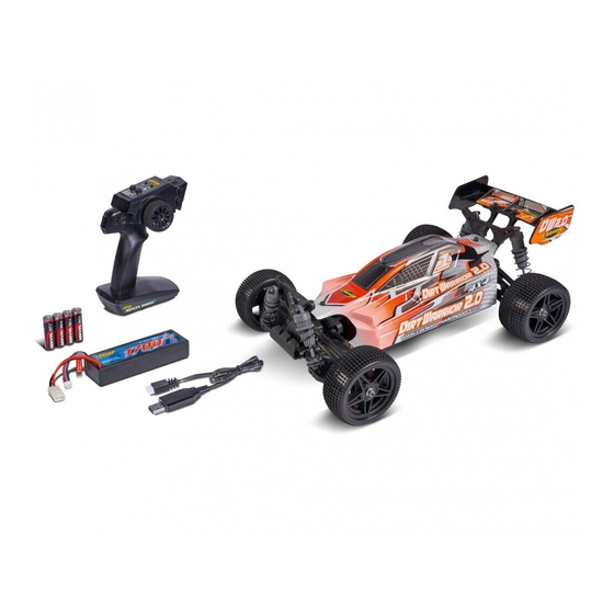
X10 Dirt Warrior Sport 2.0
X10 Monster Warrior XL 2.0
ASSEMBLED READY-TO-RUN MODEL
Achtung - Attention - Attention
Attenzione - Atención - Pas op
DE // Betriebsanleitung
GB // Instruction Manual
FR // Avertissement de sécurité
IT // Avvertenze di sicurezza
ES // Indicaciones de seguridad
NL // Veiligheidsinstructies
Montageanleitung - Instructions
Ersatzteile - Spare Parts
500404199 / 500404223 // Stand: Oktober 2020
02
03 - 11
12 - 20
21 - 23
24 - 26
27 - 29
30 - 32
33
51
Publicité
Chapitres
Table des Matières

Manuels Connexes pour Carson X10 Dirt Warrior Sport 2.0


Sommaire des Matières pour Carson X10 Dirt Warrior Sport 2.0
- Page 1 X10 Dirt Warrior Sport 2.0 X10 Monster Warrior XL 2.0 ASSEMBLED READY-TO-RUN MODEL Achtung - Attention - Attention Attenzione - Atención - Pas op DE // Betriebsanleitung 03 - 11 GB // Instruction Manual 12 - 20 FR // Avertissement de sécurité...
- Page 2 Handbuch enthält die technischen Anlagen, wichtige Den aktuellsten Stand ihres Handbuches finden sie unter: Anleitungen zur korrekten Inbetriebnahme und Nutzung sowie www.carson-modelsport.com Produktinformation entsprechend dem aktuellen Stand vor der GB // Important information Before using your product for the first time or ordering any spare date before going to press.
- Page 3 Ansprüche abgeleitet werden. Garantiebedingungen Von der Garantie ausgeschlossen sind: Für dieses Produkt leistet CARSON eine Garantie von 24 Monaten • Beschädigung oder Ausfall durch Nichtbeachten der Sicher- betreffend Fehler bei der Herstellung in Bezug auf Material und heitsanweisungen oder der Bedienungsanleitung, höhere...
-
Page 4: Table Des Matières
INHALT Vorwort ........................3 Einlegen der Senderbatterie ................9 Lieferumfang Zubehör ..................4 Einschalten der RC-Anlage................9 Sicherheitsanweisungen .................5 Binding ........................9 Sicherheitsanweisungen Lithium Akkus ...........6 Steuern des Modells ..................10 Chassis ........................7 Steuerung der LED-Beleuchtung ............... 10 Abnehmen der Karosserie ................7 Fehlersuche ......................11 Aufladen des Fahrakkus..................8 Montageanleitung .................. -
Page 5: Sicherheitsanweisungen
SICHERHEITSANWEISUNGEN Sicherheitsanweisung und bestimmungsgemäße Verwendung Dieses Produkt ist ausschließlich für Hobbyzwecke ausgelegt und Bitte beachten sie, dass es bei verschiedenen Modellen zu erhöh- darf nur auf dafür vorgesehenen Plätzen benutzt werden. ten Geräuschpegeln kommen kann, daher dürfen diese nicht dauerhaft in ihrer unmittelbarer Umgebung betrieben werden. Mit diesen Modell dürfen keine Personen oder Tiere transportiert werden. -
Page 6: Sicherheitsanweisungen Lithium Akkus
• Akku während des Ladens und/oder Betriebs niemals Betriebshinweisen, sowie des Ersatzes des Akkus und dessen unbeaufsichtigt lassen. Wartung nicht möglich ist, kann Tamiya/Carson keinerlei Haftung für Verluste, Schäden oder Kosten übernehmen. • Unbedingt empfohlene Lade-/Entladeströme einhalten. Jeglicher Anspruch auf Schadenersatz, der sich durch den Betrieb, •... -
Page 7: Chassis
CHASSIS Spoiler Motor Hintere Stoßdämpfer Schalter EIN / AUS am Empfänger / Fahrregler Lenkservo Vorderreifen Hinterreifen Schalter EIN / AUS Beleuchtung Vorderer Stoßdämpfer Chassis ABNEHMEN DER KAROSSERIE • Ziehen Sie die Karosseriesplinte (2) heraus und • Nehmen Sie die Karosserie ab. 7 // DE... -
Page 8: Aufladen Des Fahrakkus
AUFLADEN DES FAHRAKKUS grüne LED rote LED LiPo 7.4 V 1700 mAh EINLEGEN DER FAHRAKKUS 1 Legen Sie die Akkus ein. 2 Setzen Sie die Abdeckung auf und 3 Fixieren Sie mit den Schraubmuttern. Hinweis: • Trocken-Batterien sind nicht wiederaufladbar. •... -
Page 9: Einlegen Der Senderbatterie
EINLEGEN DER SENDERBATTERIE 1. Öffnen Sie den Batteriedeckel an der Unterseite des Senders. 2. Legen Sie vollständig geladene Akkus oder neue Batterien der Größe AA/Mignon ein. Achten Sie auf die richtige Polarität. Schließen Sie das Batteriefach anschließend wieder mit dem Deckel. -
Page 10: Steuern Des Modells
STEUERN DES MODELLS • Stellen Sie das Modell so ab, dass die Räder frei in der Luft hängen. • Drehen Sie das Steuerrad bis zum Anschlag nach rechts und links. Die Räder sollen dem Lenkausschlag folgen. • Zum Regeln der Fahrgeschwindigkeit betätigen Sie den Gas/ tral Bremshebel - nach hinten (Vorwärtsfahrt, Gas geben) bzw. -
Page 11: Fehlersuche
FEHLERSUCHE Problem Ursache Lösung Das Modell fährt nicht Sender oder Empfänger sind nicht einge- Schalten sie den Sender oder Empfänger ein schaltet Polarität der Akkus oder Akkutyp sind falsch Prüfen Sie die Polarität und den Akkutyp Tauschen Sie die Batterien aus bzw. tau- Batterien/Akkus sind schwach oder ganz schen Sie die Akkus oder laden sie die Akkus entleert... - Page 12 • Damage caused by losing control of your model; CARSON will, at its option, unless otherwise provided by law: • Any repairs other than those provided by a CARSON authorised (a) Correct the defect by repairing the product without charging service facility;...
- Page 13 CONTENTS Preface ........................12 Installing the transmitter batteries ............18 Included Items Accessories ................13 Turn on the RC System ..................18 Safety Precautions ................... 14 Binding ......................... 18 Safety Precautions lithium batteries ............15 How to Control Your Model................19 Chassis ........................16 Control of the LED lighting ................
-
Page 14: Safety Precautions
SAFETY PRECAUTIONS Safety Instructions and Intended Use This product is designed exclusively for hobby use and may only Please note that various models can generate very high noise be used on tracks and areas intended for this purpose. levels and should, therefore, not be operated in your immediate proximity. -
Page 15: Safety Precautions Lithium Batteries
Tamiya / Carson can accept no liability for loss, damage or costs incurred. • Do not fail to keep to the recommended charge/discharge current. Any claim for damages that may result from operation, failure or faulty operation or that is in any way related thereto will therefore •... -
Page 16: Chassis
CHASSIS Spoiler Motor Rear shock unit Switch ON / OFF on the receiver / speed controller Steering Servo Front tyre Rear tyre Light ON/OFF Front shock unit Chassis REMOVING THE BODY • Remove hook pin (2) and • Take body off. GB // 16... -
Page 17: Charge Battery Pack
CHARGE BATTERY PACK LED green LED red LiPo 7.4 V 1700 mAh INSERTING THE DRIVE BATTERIES 1 Insert the batteries 2 Put the battery plate on it and 3 Fix it with the screw-nuts Advice • Non-rechargeable batteries are not to be recharged. •... -
Page 18: Installing The Transmitter Batteries
INSTALLING THE TRANSMITTER BATTERIES 1. Open the battery compartment lid on the underside of the transmitter. 2. Insert fully charged rechargeable batteries or new AA bat- teries observing the correct polarity. Close the cover on the battery compartment again. Ensure that the cover clicks properly into place. -
Page 19: How To Control Your Model
HOW TO CONTROL YOUR MODEL • Raise the tyres off the ground • Turn the steering wheel to the right and left as far as it will go. The wheels are to follow the steering direction. • If the wheels operate in the opposite direction, operate the servo tral Reverse switch (ST in position REV). -
Page 20: Troubleshooting
TROUBLESHOOTING Problem Cause Correction Model doesn´t move Transmitter or chassis power switch is not Switch power on receiver or transmitter ”ON“ Polarity or battery type is wrong Check polarity and type of battery Batteries have run down Change batteries or charge them Loss of control Batteries have run down Change batteries or charge them... - Page 21 Conditions de garantie La garantie ne couvre pas: Pour le présent produit, CARSON offre une garantie de 24 mois à • Tout dommage ou défaillance causé par force majeure, abus, compter de la date d‘achat chez un distributeur autorisé et couvre accident, utilisation abusive, erronée ou anormale, non respect...
- Page 22 CONSIGNES DE SÉCURITÉ Consignes de sécurité et utilisation conforme Ce produit a été exclusivement conçu à des fins de loisir et ne doit niveau de bruit peut être élevé. Pour cette raison, veuillez ne pas être utilisé qu’à des endroits prévus à cet effet. les faire fonctionner de façon permanente auprès de vous.
- Page 23 • Respectez impérativement les courants de charge et de TAMIYA / CARSON refuse toute prise en charge des pertes, décharge recommandés. dommages et frais entraînés.
- Page 24 Condizioni di Garanzia Dalla garanzia sono esclusi: CARSON offre una garanzia di 24 mesi, dalla data di acquisto, • Danni o cadute derivanti dalla mancata osservanza delle contro eventuali difetti di materiale o di fabbricazione nel caso istruzioni d‘uso e di sicurezza, da cause di forza maggiore,...
- Page 25 ISTRUZIONI DI SICUREZZA Istruzioni di sicurezza e uso conforme Questo prodotto, progettato esclusivamente a scopo di svago, Dato che alcuni modelli possono raggiungere livelli di può essere impiegato unicamente in spazi appositamente rumore particolarmente elevati, si raccomanda di non tenerli previsti.
- Page 26 TAMIYA / CARSON declina ogni responsabilità • Rispettare scrupolosamente le correnti di caricamento/ legata a perdite, danni o costi.
- Page 27 • Daños derivados de la pérdida de control del producto CARSON, en función de su propio criterio, y si en la ley no se esta- • Reparaciones realizadas por un servicio no autorizado por...
- Page 28 INSTRUCCIONES DE SEGURIDAD Directiva de seguridad y uso conforme Este producto ha sido diseñado exclusivamente para fines de ocio niveles sonoros muy elevados, de ahí que estos no deban ser y solo debe ser usado en los lugares previstos para ello. utilizados de forma permanente cerca de su entorno.
- Page 29 TAMIYA / CARSON no puede asumir ningún tipo de responsabilidad por pérdidas, daños o costes. • Respetar siempre la corriente de carga/descarga recomendada.
- Page 30 Garantievoorwaarden Uitgesloten van de garantie zijn: CARSON verleent een garantie van 24 maanden op dit product in • Beschadiging of uitval door niet-naleving van de veiligheids- geval van fabricagefouten in het materiaal en vakmanschap bij...
- Page 31 VEILIGHEIDSINSTRUCTIES Veiligheidsinstructies en doelmatig gebruik Dit product is uitsluitend ontworpen voor hobbydoeleinden en produceren. Daarom mogen deze modellen alleen maar kortston- mag alleen op daarvoor geschikte plaatsen worden gebruikt. dig in uw directe omgeving worden gebruikt. Met dit product mogen geen personen of dieren worden vervoerd. Let er voor het begin van elke rit op dat de tankdop goed gesloten is en dat de accu correct is aangesloten.
- Page 32 TAMIYA / CARSON geen enkele aansprakelijkheid • Houd u beslist aan aanbevolen laad-/ontlaadstromen. voor verlies, schade of kosten aanvaarden.
-
Page 33: Assembly Instructions
MONTAGEANLEITUNG • ASSEMBLY INSTRUCTIONS 1. CHASSIS • CHASSIS 500405873 500405873 500405344 3 x 10 mm 500405571 3 x 10 mm 2. MOTORHALTER • ENGINE MOUNT 500405356 500405571 3 x 10 mm... - Page 34 3. RUTSCHKUPPLUNG • SLIPPER CLUTCH Hier eine Anleitung zur Rutschkupplung, die sowohl zur Antriebs- Here is the manual for the slipper-clutch device that offers both steuerung als auch zum Schutz des Getriebes dient. In erster traction control and protection for the transmission. The slipper is Linie dient sie dazu, plötzliche starke Stöße auf die Antriebswelle primarily used to help absorb sudden impacts on the drivetrain due abzufangen, wie sie bei weiten Sprüngen oder hartem Gelände...
- Page 35 4. MONTAGE MOTOR • MOTOR ASSEMBLY Auf ausreichend Spiel achten! Please pay attention for right space! 4 x 4 mm (Set) 21 T 500405879 23 T 500405876 500405571 3 x 14 mm 5. MONTAGE SERVO • SERVO ASSEMBLY 90 ° 500405571 500405571 3 x 8 mm...
- Page 36 6. MONTAGE DIFFERENZIAL • DIFF ASSEMBLY 2.5 x 8 mm 500405575 500405575 500405576 3 x 8 mm 3 x 8 mm 500405361...
- Page 37 7. DÄMPFERBRÜCKE HINTEN • REAR SUSPENSION MOUNT 500405346 3 x 12 mm 3 x 10 mm 500405346 8. MONTAGE ANTRIEB • DRIVE ASSEMBLY 3 x 16 mm 3 x 8 mm 3 x 16 mm 500405353 500405571 500405353 500405361...
- Page 38 9. GETRIEBEBOX • GEAR HOUSING 3 x 16 mm 3 x 8 mm 500405353 3 x 16 mm 500405353 500405346 500405575 500405346 10. DÄMPFERBRÜCKEN • SUSPENSION MOUNTS 3 x 10 mm 3 x 12 mm 3 x 10 mm 500405346 3 x 10 mm...
- Page 39 11. MONTAGE LENKUNG • STEERING ASSEMBLY 500405360 3 x 10 mm 500405360 500405360 500405360 3 x 10 mm...
- Page 40 12. MONTAGE LENKUNG • STEERING ASSEMBLY 500405578 3 x 10 mm 3 x 10 mm 3 x 10 mm 3 x 10 mm 3 x 10 mm 500405571 500405346...
- Page 41 13. MONTAGE ANTRIEB VORNE • FRONT DRIVE ASSEMBLY 500405446 500405445 500405570 500405354 500405354 500405354 500405445 500405570 500405354 500405354 500405354...
- Page 42 14. MONTAGE QUERLENKER • SUSPENSION ARMS ASSEMBLY 3 x 5 mm 500405350 500405351 500405350 500405351 500405350 3 x 10 mm 500405873...
- Page 43 15. MONTAGE GESTÄNGE • TURNBUCKLE ASSEMBLY 500405578 500405578...
- Page 44 16. MONTAGE LENKUNG • STEERING ASSEMBLY 500405578 500405578 500405352 500405445 500405570 500405447...
- Page 45 17. QUERLENKER HINTEN • REAR SUSPENSION ARMS 500405360 3 x 5 mm 500405351 500405350 3 x 5 mm 500405352 500405350 500405351 500405873 500405873 500405350 3 x 8 mm 500405873 500405873...
- Page 46 18. MONTAGE ANTRIEBSKNOCHEN • DOGBONES ASSEMBLY 500405578 500405447...
- Page 47 19. MONTAGE FRONTRAMMER • ASSEMBLY BUMPER 500405571 3 x 6 mm 3 x 10 mm...
- Page 48 20. FAHRREGLER-EINHEIT • ESC-UNIT Fahrregler / ESC-Unit 21. MONTAGE AKKUHALTER • BATTERY HOLDER ASSEMBLY 500405834 3 x 8 mm...
- Page 49 22. MONTAGE RÄDER • WHEEL ASSEMBLY 500405445...
- Page 50 23. KAROSSERIE + SPOILER • BODY + WING 500800105/06...
-
Page 51: Spare Parts
ERSATZTEILE • SPARE PARTS 500405344 Querlenkerhalter-Set v/h 500405353 4 x Obere Querlenkerhalter 500405360 Servosaver / Lenkeinheit Suspension armholder set f/l v/h / 4 x Upper turnbuckle Servosaver / steering set holder f/r 500405346 Getriebegehäuse Set Gear box set 500405350 Querlenker- / 500405354 2 x Achsschenkel-Set vorne 500405361 Rutschkupplung-Set + Achsschenkelstifte v/h... - Page 52 ERSATZTEILE • SPARE PARTS 500405570 Gleit Lager-Set 500405834 Akkuhalter-Set 500405875 Stoßdämpfer(4) Kunststoff grau POM bearing set Battery holder set Shock absorber plastic grey (4) 500405571 Chassis / Anbauteile-Set 500405835 Abdeckung Hauptzahnrad 500405876 Motorritzel 23 T Motor gear cover Pinion Gear 23 T Chassis plates replacement set 500405575 Differenzial vorne komplett 500405873 Querlenkerhalter-Set...
- Page 53 ERSATZTEILE • SPARE PARTS 500405836 Dämpferbrücken v/h 500606089 USB-Lader 7,4V 1A 500800105 Karosserie /Spoiler Set Shock towers front / rear USB charger Body / Wing Set ERSATZTEILE • SPARE PARTS 500404223 MOUNTAIN WARRIOR XL 500405877 Stoßdämpfer(4) Kunststoff rot 500405878 Mountain Warrior XL 500405879 Motorritzel 21 T Shock absorber plastic red (4) Räderset (4) / Mountain...
- Page 54 NOTIZEN / NOTES...
- Page 56 Werkstraße 1 // D-90765 Fürth // www.carson-modelsport.com +49 3675 7333 343 Service-Hotline for Germany: Mo - Do 8 -12 Uhr & 12.30 -16 Uhr // Fr 8 -12.30 Uhr CARSON-Model Sport // Abt. Service // Mittlere Motsch 9 // 96515 Sonneberg...