Field Controls GVD-4 Mode D'emploi
Table des Matières
Les langues disponibles
Les langues disponibles
Field Controls (GVD) gas vent damper was developed to reduce off cycle venting losses through boilers and
draft hoods.
When,
the boiler is in a standby
boiler and the condition space. To significantly reduce these losses install a Field Controls Gas Vent
Damper. The damper is installed in the vent and as close to the draft hood as practical. When properly
installed the damper opens before the burner fires and closes after the burner shuts off. The electrical
circuits in this product are designed not to override the existing limit and safety controls of the boiler.
CAUTION
The plug is installed only if the
appliance is equipped with an intermittent or direct
ignition system. Failure to follow these instructions can
cause odor problems and minor property damage due
to moisture. Do not install on standing pilot systems.
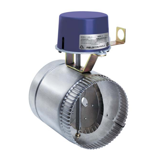
GAS VENT DAMPER
Model: GVD-4 through 12
mode.
Heat escapes up the chimney. The heat comes from the
English........... Page 1
Français......... Page 13
Tape Plug
Here
Tape Plug
Here
Table des Matières

Manuels Connexes pour Field Controls GVD-4


Sommaire des Matières pour Field Controls GVD-4
-
Page 20: Système De Registre D'évacuation Pour Mazout
Homologué UL-17 et CSA B140.14 Le registre d’évacuation pour mazout (OVD) Field Controls réduits les pertes à vide à travers les appareils de chauffage au mazout. Lorsque l’appareil est en mode de veille, la chaleur s’échappe par la cheminée. Cette chaleur provient de l’appareil et de l’espace environnant. -
Page 21: Caractéristiques
ARACTÉRISTIQUES 1. Commutateur de servie – Tient le registre ouvert et permet à l’appareil de fonctionner sans que le registre fonctionne. 2. Garantie limitée de 18 mois sur le mécanisme motorisé à compter de la date de fabrication. 3. Deux contacteurs de sécurité internes. 4. -
Page 22: Avertissements Avant Installation
3. Le registre d’évacuation automatique Field Controls peut uniquement être posé sur des appareils au mazout à fonctionnement automatique qui utilisent des brûleurs électriques à atomisation. 4. Le registre d’évacuation automatique Field Controls ne doit pas être posé sur des appareils au mazout à ventouse, à chambre de combustion fermée ou à brûleurs à vaporisation. -
Page 23: Contrôle De Sécurité
NSTRUCTIONS DE DÉBALLAGE 1. Le registre d’évacuation Field Controls série OVD est emballé dans un carton unique. Il contient un registre OVD assemblé, un contacteur de sécurité WMO-1 précâblé avec joint en fibre et faisceau de câbles à... -
Page 24: Pose Sur Conduit Vertical
OSE DU SYSTEME AVERTISSEMENT : Poser le système de registre d’évacuation de manière à desservir seulement l’appareil unique auquel il est destiné. Une pose incorrecte peut présenter un danger d’explosion, d’intoxication au monoxyde de carbone ou de mort. ’ OSE DU BOUCHON D ÉVACUATION ATTENTION... - Page 25 EN CAS D’APPAREILS MULTIPLES, CHAQUE APPAREIL DOIT AVOIR SON PROPRE REGISTRE D’ÉVACUATION OVD CHEMINÉE OU SYSTÈME D’ÉVACUATION NE PAS POSER LE DÉGAGEMENT DE BORD RABATTU REGISTRE OVD EN AVAL 457 mm (18 po) DU REGISTRE DE PLUS D’UN APPAREIL VERS MATÉRIAU COMBUSTIBLE Cheminée ou système...
-
Page 26: Instructions De Cablage
Section Longueur de tuyau A tuyau à mm (po) couper mm (po) (3-1/2) VIS OU RIVET AVEUGLE EN (3-1/2) TROIS ENDROITS ESPACE POUR SUR CHAQUE COUPER VOIR TABLEAU REGISTRE OVD RACCORD BORD RABATTU 51 mm (2 po) MINIMUM 29 mm (1-1/8 po) (4-9/16) LE FAISCEAU DE FILS DE... - Page 31 CAVALIER...
- Page 32 LE NOIR, L’ORANGE ET LE JAUNE DU REGISTRE D’ÉVACUATION DOIVENT ÊTRE DE MÊME POLARITÉ POUR ÉVITER LES DOMMAGES DU PRODUIT. AVERTISSEMENT : • DÉBRANCHER L’ALIMENTATION GOUPILLE FENDUE ET ÉLECTRIQUE AVANT DE CÂBLER RONDELLE LE REGISTRE D’ÉVACUATION ! COMMUTATEUR • LE REGISTRE DOIT ÊTRE INDICATEUR DE SERVICE DE POSITION...
-
Page 33: Entretien
ENTRETIEN WMO-1 YSTEME DE COUPURE DE SECURITE Pour assurer un fonctionnement sans danger, la combinaison appareil-commutateur doit être contrôlée et entretenue chaque année par un organisme qualifié. 1. Débrancher l’alimentation électrique de l’appareil. 2. Desserrer les deux vis de fixation du couvercle du contacteur de blocage d’évacuation WMO-1. 3. - Page 34 UIDE DE RÉSOLUTION DES PROBLÈMES ATTENTION • Lors de travaux sur les commandes, tous les fils doivent être étiquetés avant d’être débranchés. Les erreurs de câblage peuvent résulter en un mauvais fonctionnement dangereux. • Ne pas ouvrir le registre à la main car cela endommage le moteur et annule la garantie. NE PAS COUPER LA FICHE DU MOTEUR DE REGISTRE CAR CELA ANNULE LA GARANTIE.
-
Page 35: Solution Conseillée
PROBLÈME CAUSE POSSIBLE SOLUTION CONSEILLÉE Le registre d’évacuation peut prendre jusqu’à 12 minutes pour se fermer lors du premier cycle. Après le premier cycle, il se ferme en 3 minutes environ. S’assurer que le commutateur de Commutateur de service en position de service est en position automatique. -
Page 36: Appareils De Combustion Au Mazout
’ ’ ONNEES D EXPLOITATION INITIALES SUR LE BRULEUR ET LE SYSTEME D EVACUATION Consigner les données suivantes pour l’appareil fonctionnant avec un dispositif OVD sur son système d’évacuation, pour référence lors des réglages ou de la maintenance annuels. Date APPAREILS DE COMBUSTION AU MAZOUT Taille du gicleur de brûleur au mazout... - Page 37 Garantie limitée Limited Warranty Field Controls, L.L.C. garantit que les produits Field Controls, L.L.C. suivants vendus aux présentes sont exempts de défauts de matériaux et de Field Controls, L.L.C. warrants that the following Field Controls, L.L.C. products sold hereunder, shall be free from defects in material and workmanship under main-d’œuvre dans des conditions normales d’utilisation pendant dix-huit (18) mois à compter de la date de fabrication par le consommateur sous normal use for eighteen (18) months from date of manufacturing by the consumer excepting the provisions numbered below. ...
-
Page 38: Electrical Data
OPERATION When the boiler receives a call for heat, the damper rotates to the open position before the burner circuit is energized. If the damper does not rotate to the open position, the burner circuit will not be energized. When properly installed, the electrical circuits in this product are designed not to override the existing limit and safety controls of the appliance. - Page 39 UNPACKING INSTRUCTIONS 1. The Field Controls GVD Series Gas Vent Damper is packaged in a single carton containing an assembled GVD, instruction manual and a plug. NOTE: Some OEM supplied units have the wiring harness attached. 2. Inspect for damage prior to the installation.
- Page 40 Safety Inspection 1. Conduct a gas leakage test of the appliance piping and control system downstream of the shutoff valve in the supply line to the appliance. 2. Visually inspect the venting system for proper size, horizontal pitch and vent termination, and determine there is no blockage or restriction, leakage, corrosion and other deficiencies which could cause an unsafe condition.
- Page 41 HOW TO INSTALL AN ADDITIONAL GAS VALVE Determine if the appliance has a redundant gas valve. If it has a redundant gas valve proceed to install the damper assembly. WARNING: If the appliance does not have a redundant gas valve, an additional gas valve or a redundant gas valve must be installed.
- Page 42 INSTALLATION OF THE UNIT WARNING: Install the automatic vent damper to service only the single appliance for which it is intended. See Figure 4. If improperly installed a hazardous condition such as an explosion or carbon monoxide poisoning could result. WARNING: To be used only with an appliance bearing a marking showing the make and model of the device.
- Page 43 PPLIANCE IRING 1. To locate the vent damper wire harness (if supplied) receptacle on the appliance, refer to the appliance manufacturer instruction manual and follow accordingly. (See Figures 5,6,7) 2. The wire harness shall be securely fastened thru the conduit bracket, located on the vent damper motor assembly.
- Page 44 The following steps are to be followed in making the modifications: 1. Perform a safety inspection of the existing appliance installation. See PRE-INSTALLATION INSPECTIONS section for the recommended procedure for such a safety inspection. 2. Shut off all gas and electricity to the appliance. To shut off gas use the shutoff valve in the supply line to the appliance. 3.
- Page 45 WIRING All electrical work and materials used in the vent damper installation shall be in accordance with local electrical codes. In the absence of codes, consult the National Electrical Code. To avoid damage to the room thermostat heat anticipator turn off the electrical power supply to the appliance before proceeding with the wiring.
- Page 46 PROBLEM POSSIBLE CAUSE RECOMMENDED SOLUTION 1. Off on limit (120VAC) 1. Turn limit on. 2. Bad Transformer. 2. Replace transformer. 3. Loose or broken connections. 3. Tighten, repair or replace connection. NO POWER 4. Blown fuse or circuit breaker. 4. Replace fuse or reset circuit breaker. Between 4&1 5.
- Page 47 ROUBLE HOOTING ITH A UMPER IRE IN LACE PROBLEM POSSIBLE CAUSE RECOMMENDED SOLUTION 1. Is gas turned on. 1. Make sure gas is on. 2. Operating limit, pressure control or 2. Make sure operating limit, pressure POWER ON low water cut off not on. control or low water cut off is on.
- Page 48 Page 12...
-
Page 49: Registre D'évent À Gaz
Modèles : GVD-4 à 12 Field Controls a mis au point les registres d’évent à gaz de série GVD afin de réduire les pertes de chaleur par le conduit d’évacuation de la chaudière et du coupe-tirage pendant les cycles d’arrêt. Lorsque la chaudière est en mode d’attente, la chaleur provenant de la chaudière et de l’espace d’air conditionné... -
Page 50: Installation Électrique
NSTRUCTIONS DE DÉBALLAGE 1. Le registre d’évent à gaz Field Controls de série GVD est livré dans une seule caisse en carton contenant le registre assemblé, la notice technique et un bouchon. NOTA : Certains appareils vendus par des constructeurs OEM sont livrés avec un câble d’alimentation. -
Page 51: Inspections Préalables À L'installation
12. Ce registre ne doit être installé que sur un appareil au gaz homologué, raccordé à une cheminée ou un conduit d’évacuation préfabriqués obéissant à une norme reconnue, ou à une cheminée de maçonnerie ou de béton dont le revêtement interne est approuvé... - Page 52 Inspection de sécurité 1. Effectuer un test de repérage de fuite de gaz sur la tuyauterie et le système de régulation de l’appareil en aval du robinet d’arrêt du tuyau d’alimentation de l’appareil de chauffage. 2. Faire une inspection visuelle du système d’évacuation afin de vérifier si les dimensions et la pente horizontale du système ainsi que l’extrémité...
-
Page 53: Installation D'un Robinet D'admission De Gaz Additionnel
INSTALLATION D’UN ROBINET D’ADMISSION DE GAZ ADDITIONNEL Vérifier si l’appareil est équipé d’un robinet de gaz redondant. Dans l’affirmative, procéder à l’installation du registre. AVERTISSEMENT – Si l’appareil n’est pas équipé d’un robinet de gaz redondant, on doit y installer un robinet de gaz additionnel ou un robinet redondant. -
Page 54: Installation Du Registre
INSTALLATION DU REGISTRE AVERTISSEMENT – Installer le registre automatique de manière qu’il ne desserve que l’appareil auquel il est destiné (Schéma 4). Une installation incorrecte pourrait créer des conditions dangereuses susceptibles de provoquer notamment une explosion ou un empoisonnement au monoxyde de carbone. AVERTISSEMENT –... -
Page 55: Câblage Électrique De L ' Appareil De Chauffage
’ ÂBLAGE ÉLECTRIQUE DE L APPAREIL DE CHAUFFAGE 1. Consulter la notice technique du fabricant de l’appareil de chauffage pour connaître l’emplacement de la prise sur laquelle doit être branché (s’il est fourni) le câble d’alimentation du registre. (Schémas 5, 6 et 7) 2. - Page 56 La procédure suivante doit être observée pour effectuer les modifications. 1. Effectuer une inspection de sécurité de l’appareil en suivant la procédure décrite à la rubrique INSPECTIONS PRÉALABLES À L’INSTALLATION. 2. Couper l’arrivée de gaz (au moyen du robinet d’arrêt installé sur le tuyau d’alimentation de l’appareil) et l’alimentation électrique de l’appareil.
- Page 57 15. Consigne applicable uniquement aux générateurs de chaleur – Vérifier le fonctionnement du limiteur et de la commande du ventilateur. On peut vérifier le fonctionnement du limiteur en obturant la prise d’air de circulation ou en coupant provisoirement l’alimentation électrique du ventilateur et en vérifiant si le limiteur déclenche la coupure de l’alimentation du brûleur principal. 16.
-
Page 58: Problèmes Et Solutions
PROBLÈMES ET SOLUTIONS ATTENTION – Lorsque les commandes font l’objet de travaux d’entretien et de réparation, étiqueter tous les fils avant de les débrancher. Une erreur de branchement peut entraîner un fonctionnement incorrect ou dangereux. Ne tournez pas l'amortisseur ouvert manuellement ou les dommages de moteur résulteront et vider la garantie, utilisez le commutateur de service. -
Page 59: Solution Recommandée
ÉPANNAGE AVEC UN CAVALIER IMPORTANT – Le registre doit être OUVERT avant que le brûleur ne s’allume. PROBLÈME CAUSE POSSIBLE SOLUTION RECOMMANDÉE 1. Robinet d’admission de gaz 1. Ouvrir le robinet de gaz. fermé. 2. Limiteur, régulateur de pression 2. Mettre le limiteur, le régulateur ou ou interrupteur de bas niveau l’interrupteur en fonction. - Page 60 P/N 46352700 Rev F 04/07 Page 24...