Publicité
Les langues disponibles
Les langues disponibles
Liens rapides
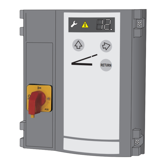
TA MS
400V / 230V
Software Release R1.20
6mm
T 20
0
2
RETU RN
2
3
Montage- und
D
Bedienungsanleitung
Mounting and operating
GB
instructions
FR
Notice de pose et
d'utilisation
Instrucciones de
ES
montaje y de manejo
Montage- en
NL
bedieningshandleiding
PL Instrukcja montażu i
obsługi
1
182 mm
Publicité

Manuels Connexes pour Novoferm TA MS 400V / 230V


Sommaire des Matières pour Novoferm TA MS 400V / 230V
- Page 1 Montage- und TA MS Bedienungsanleitung 400V / 230V Mounting and operating instructions Software Release R1.20 Notice de pose et d'utilisation Instrucciones de montaje y de manejo RETU RN Montage- en bedieningshandleiding PL Instrukcja montażu i obsługi 182 mm T 20...
- Page 2 Anschlussübersicht Connection diagram Vista general de las conexiones Schéma de connexion Aansluitklemmenschema Schemat łączy...
- Page 3 1.1 1.1 1.2 1.1 1.3 1.1 4.1 1.1 4.2 1.1 4.3 1.1 L1´ L2´ L3´ N´ 3 x 400V, N, PE U2 V2 4.1 1.1 4.2 1.1 4.3 1.1 1.1 1.1 1.2 1.1 1.3 1.1 L1´ L2´ L3´ 3 x 230V, PE U2 V2 W2...
- Page 4 1.1 2.2 230V max. 2A 230V max. 2A max. 100mA J1.1 J1.2 J1.3 J1.4 J4.1 J4.2 J4.3 J4.4...
- Page 8 Zusätzlich müssen die normativen Verweise der • Allgemeine Informationen aufgeführten Normen beachtet werden. VDE-Vorschriften • Sicherheit - DIN EN 418 Vor Beginn sämtlicher Arbeiten am Produkt die TA MS Sicherheit von Maschinen Betriebsanleitung, insbesondere das Kapitel NOT-AUS-Einrichtung, funktionelle Aspekte Sicherheit und die jeweiligen Sicherheitshinweise, Gestaltungsleitsätze vollständig lesen.
- Page 9 Installation Potentialfreie Relaisausgänge Optisches und akustisches Warnsignal an X5 und Benötigte Werkzeuge Verladeleuchte an X6 anschließen. Montage Steuerung Externe Bedienkonsole Für die Bedienung der Überladebrücke kann an J1 Öffnen der Steuerungsabdeckung eine externe Bedienkonsole angeschlossen werden. Anschlüsse Die Überladebrücke muss von dem Ort der Bedienung einsehbar sein.
- Page 10 • Wartung / Überprüfung Betriebsanleitung / Wiederanlaufsperre Nach dem Wiedereinschalten des Hauptschalters Funktionsbeschreibung Die Überladerbrücke- und Toranlage oder des Not-Aus-Tasters ist die Wiederanlauf- muss bei der Inbetriebnahme und nach sperre aktiv, die gelbe Warnanzeige blinkt In diesem Kapitel beschreiben wir Ihnen den Bedarf - jedoch mindestens einmal kompletten Betrieb der Überladebrücke.
- Page 11 Programmierübersicht Menü Item Enter Exit Ein- Menü- Ein- Menü- Auswahl Auswahl gabe Punkt gabe Punkt Überstrom Motorpumpe Funktion Schlüsselschalter (J7) 0,0 A keine Funktion 2,6 A Bedienfeld sperren 3,2 A externe Bedienelemente sperren 3,8 A 4,4 A Bedienfeld und externe Bedienelemente sperren 5,0 A Bedienelemente für 10 Sekunden aktivieren 5,6 A...
- Page 12 Fehlerdiagnose Fehler Zustand Diagnose / Abhilfe keine Reaktion Not-Aus-Kreis unterbrochen. Anschluss J4 überprüfen. Netzspannung fehlerhaft Phasen kontrollieren. Drehrichtung ändern. keine Reaktion Fehler bei Selbsttestung aufgetreten. Steuerung tauschen. keine Reaktion Fehler bei Selbsttestung aufgetreten. Steuerung tauschen. keine Reaktion Fehler bei Selbsttestung aufgetreten. Steuerung tauschen.
- Page 13 • General Information In addition to the above, the normative references of the standards listed must be observed. • Safety VDE regulations Before commencing any work on the product, - DIN EN 418 TA MS Safety of Machinery carefully read through the operating instructions Emergency-STOP device, functional aspects from start to finish, in particular the section entitled Design principles...
- Page 14 Installation Floating relay output Connect the visual and audible warning signals to X5 Required tools and dock light to X6. Installing the control unit External operating panel Opening the control unit cover An external operating panel (remote control) can be connected with J1 for operating the dock leveller.
- Page 15 Maintenance / Checks Operating instructions / Return / dock leveller at zero position If loading is complete, the dock leveller can be Description of function returned to zero position by pressing the RETURN For your own safety, we recommend button. that prior to initial operation and The dock leveller lifts and then lowers automatically whenever required - however at least...
- Page 16 Programming Overview Menu Item Enter Exit Menu- Menu- Entry Entry Selection Selection point point Motor pump overcurrent Function key switch (J7) 0,0 A No function 2,6 A Block control panel 3,2 A Block external control elements 3,8 A 4,4 A Block control panel and external control elements 5,0 A Activating the control elements for 10 secs.
- Page 17 Error Diagnosis Error State Diagnosis / Remedy No reaction Emergency stop circuit interrupted. Check terminal J4. Incorrect mains voltage Inspect phases, change rotation No reaction Error occurred during self-testing , exchange control unit. No reaction Error occurred during self-testing , exchange control unit. No reaction Error occurred during self-testing , exchange control unit.
- Page 18 • Informations générales Les références normatives des normes citées doivent également être observées. • Sécurité Prescriptions VDE Lire attentivement la notice dans son intégralité - DIN EN 418 TA MS Sécurité des machines avant de commencer toute opération sur le produit, Dispositif d'arrêt d'urgence, aspects fonctionnels en particulier le chapitre concernant la sécurité...
- Page 19 Installation Sorties de relais exemptes de potentiel Raccorder un signal d'avertissement optique et Outils nécessaires sonore à X5 et un témoin de chargement à X6. Montage de la commande Unité de commande externe Ouverture du capot de la commande Pour commander le niveleur de quai, c'est possible de raccorder une unité...
- Page 20 Maintenance / Contrôle Notice d'utilisation / bien la touche d'arrêt d'urgence, le blocage anti- redémarrage est activé, le voyant d'avertissement Description des fonctions jaune clignote sur le display. Pour votre sécurité, nous vous conseillons de faire contrôler Dans ce cas, il est absolument interdit l'installation de votre niveleur de quai Fonctionnement du niveleur de quai de rouler sur le niveleur de quai.
- Page 21 Récapitulatif de programmation Menu Item Enter Exit Élément Élément N° Entry N° Entry Sélection Sélection de menu de menu Surintensité pompe moteur Fonctionnement du commutateur à clé (J7) 0,0 A Aucune fonction 2,6 A Verrouiller la console 3,2 A Verrouiller des éléments de commande externe 3,8 A 4,4 A Verrouiller la console et les éléments de commande externe...
- Page 22 Affichage des erreurs Erreur Etat Diagnostic / Remède Aucune réaction Circuit d'arrêt d'urgence interrompu. Vérifier raccord J4. Tension du réseau incorrecte Contrôler les phases, changer le sens de rotation Aucune réaction Erreur survenue pendant l'autotest. Remplacer la commande. Aucune réaction Erreur survenue pendant l'autotest.
- Page 23 • Informaciones generales Además deben observase las advertencias normativas de las normas citadas. • Seguridad Normativa de la Asociación electrotécnica Antes de iniciar cualquier trabajo en el producto se alemana (VDE) TA MS - DIN EN 418 deben leer totalmente las instrucciones de manejo, Seguridad de las máquinas en particular el capítulo Seguridad y las correspon- Dispositivo de parada de emergencia, aspectos...
- Page 24 Instalación Salidas de relé libres de potencial Conectar la señal luminosa y acústica a X5 y el piloto Herramientas necesarias de carga/descarga a X6. Montaje de la unidad de control Panel de mando externo Abrir la cubierta de la unidad control Para manejar el nivelador de muelle puede conectarse un panel de mando externo a J1.
- Page 25 Instrucciones de manejo / muelle a la posición de reposo pulsando el pulsador Mantenimiento / Comprobación RETURN. Descripción del funcionamiento Por su seguridad recomendamos que El nivelador de muelle se eleva y desciende acto una empresa especializada compruebe seguido automáticamente y sin necesidad de Operación del nivelador de muelle la instalación del nivelador de muelle accionar un pulsador a la altura del muelle de carga.
- Page 26 Guía rápida de la programación Menu Item Enter Exit Opción Opción N.° N.° Entrada Selección Entrada Selección demenú demenú Sobreintensidad motobomba Función del interruptor llave (J7) 0,0 A Sin función 2,6 A Bloquear campo de manejo 3,2 A Bloquear elementos de manejo externos 3,8 A 4,4 A Bloquear campo de manejo y elementos de manejo...
- Page 27 Indicación de errores Error Estado Diagnóstico / Remedio No hay reacción alguna Circuito de parada de emergencia interrumpido. Verificar la conexión J4. Tensión de red defectuosa Controlar fases, cambiar el sentido de rotación No hay reacción alguna Se ha producido un fallo en la comprobación automática. Cambia la unidad de control No hay reacción alguna Se ha producido un fallo en la comprobación automática.
- Page 28 • Algemene informatie Bovendien dienen ook de normatieve verwijzingen naar de genoemde normen te worden nageleefd. • Veiligheid Voorschriften van de VDE: Bij alle werkzaamheden aan het product geldt dat u - DIN EN 418 TA MS Veiligheid van machines eerst de handleiding voor het bedrijf, en wel in het Noodstopvoorzieningen, functionele aspecten bijzonder het hoofdstuk over de veiligheid en de...
- Page 29 Installatie Potentiaalvrije relaisuitgangen Optisch en akoestisch waarschuwingssignaal Benodigd gereedschap aansluiten aan X5 en laadlamp aan X6. Montage van de besturing Externe bedieningsconsole Openen van de afdekking van de besturing Voor de bediening van de overlaadbrug kan er op J1 een externe bedieningsconsole aangesloten Aansluitingen worden.
- Page 30 Onderhoud / Controle Handleiding voor het bedrijf / actief, de gele waarschuwingslamp knippert in het display. Beschrijving van de functies Ter wille van uw eigen veiligheid Het berijden van de overlaadbrug is in dit adviseren wij om de overlaadbrug Bediening van de geval verboden.
- Page 31 Overzicht programmering Menü Item Enter Exit Menu- Menu- Invoer Invoer Selectie Selectie punt punt Overstroom motorpomp Functie van de sleutelschakelaar (J7) 0,0 A Geen functie 2,6 A Bedieningsveld blokkeren 3,2 A Externe bedieningselementen blokkeren 3,8 A 4,4 A Bedieningsveld + externe bedieningselementen 5,0 A Activering bedieningselementen gedurende 10 sec.
- Page 32 Foutdiagnose Fout Status Diagnose / remedie een reactie Noodstop-kring onderbroken. Aansluiting J4 controleren. Netspanning fout Fasen controleren, draairichting veranderen. een reactie Er is een fout opgetreden tijdens de zelftest. Vervang de besturing. een reactie Er is een fout opgetreden tijdens de zelftest. Vervang de besturing. een reactie Er is een fout opgetreden tijdens de zelftest.
- Page 33 • Informacje ogólne Urządzenia zabezpieczające dla bram o napędzie silnikowym – Wymagania i k ontrole Bezpieczeństwo • Dodatkowo należy przestrzegać normatywnych Przed rozpoczęciem prac przy produkcie należy odnośników w podanych normach. TA MS przeczytać całą instrukcję obsługi, w szczególności Przepisy VDE rozdział...
- Page 34 Instalacja Podłączenie przełącznika kluczowego Aby korzystać z przełącznika kluczowego należy Potrzebne narzędzia wybrać odpowiednią opcję w menu 50. Montaż sterowania Bezpotencjałowe wyjścia przekaźników Należy połączyć optyczny i akustyczny sygnał Otwieranie przykrycia sterowania ostrzegawczy z X5 oraz lampkę ładowania z X6. Łącza Zewnętrzna konsola obsługi Oznaczenia:...
- Page 35 Instrukcja obsługi / Opis Konserwacja / Przeglądy wyświetlaczu mruga żółty sygnał ostrze gawczy. funkcji W tym wypadku zabronione jest jeżdżenie Brama powinna być poddawana po pomoście przeładunkowym. przeglądom przed rozpoczęciem Obsługa pomostu przeładunkowego eksploatacji oraz w miarę potrzeby W niniejszym rozdziale opisano pełną obsługę Powrót / pomost przeładunkowy w pozycji (przynajmniej raz w roku), pomostu przeładunkowego.
- Page 36 Funkcje programowania Menu Item Enter Exit Nr opcji / Nr opcji / Opis Opis menu menu Pozycja Pozycja Zabezpieczenie nadprądowe pompy silnika Funkcja przełącznika kluczowego (J7) 0,0 A Nieaktywna 2,6 A Panel kontrolny zablokowany 3,2 A Zewnętrzne elementy kontrolne zablokowane 3,8 A 4,4 A Panel kontrolny i elementy zewnętrzne zablokowane...
- Page 37 Diagnoza błędów Błąd Stan bramy Diagnoza / Środek zaradczy Brak reakcji Awaria w obrębie zatrzymania alarmowego, należy sprawdzić przyłączenie J4. Błędne napięcie sieci Należy sprawdzić pole obrotowe, zmienić kierunek obracania. Brak reakcji Błąd podczas samotestowania sterowania, należy wymienić sterowanie Brak reakcji Błąd podczas samotestowania, należy wymienić...