Key Automation TURBO 50 Instructions Et Avertissements Pour L'installation Et L'usage
Masquer les pouces
Voir aussi pour TURBO 50:
Table des Matières
Publicité
Les langues disponibles
Les langues disponibles
Liens rapides
Istruzioni ed avvertenze per l'installazione e l'uso
Instructions and warnings for installation and use
Instructions et avertissements pour l'installation et l'usage
Instrucciones y advertencias para su instalación y uso
Anleitungen und Hinweise zu Installation und Einsatz
Instruções e advertências para a instalação e utilização
50 - 80 - 120 -160
Management
System
ISO 9001:2008
www.tuv.com
ID 9105043769
TURBO
Motoriduttori per scorrevoli
Gear-motor for sliding gates
Motoreducteur pour coulissants
Motorreductores para rejas correderas
Getriebe für Schiebegitter
Motorredutores para portões de correr
Napęd silnikowy do bram przesuwnych
Publicité
Chapitres
Table des Matières

Manuels Connexes pour Key Automation TURBO 50


Sommaire des Matières pour Key Automation TURBO 50
- Page 1 Istruzioni ed avvertenze per l’installazione e l’uso Instructions and warnings for installation and use Instructions et avertissements pour l’installation et l’usage Instrucciones y advertencias para su instalación y uso Anleitungen und Hinweise zu Installation und Einsatz Instruções e advertências para a instalação e utilização TURBO 50 - 80 - 120 -160 Motoriduttori per scorrevoli...
-
Page 2: Table Des Matières
INDICE Avvertenze per la sicurezza pag. 3 Introduzione al prodotto pag. 4 Descrizione del prodotto pag. 4 Quadro d’insieme e caratteristiche tecniche pag. 4 Verifiche preliminari pag. 6 Installazione del prodotto pag. 6 Funzionamento manuale pag. 6 Installazione pag. 6 Fissaggio pag. - Page 3 ATTENZIONE - I dati e le informazioni indicate in questo ma- presenti; nuale sono da ritenersi suscettibili di modifica in qualsiasi mo- mento e senza obbligo di preavviso da parte di Key Automation se il cavo di alimentazione risulta danneggiato esso deve essere S.r.l.
-
Page 4: Introduzione Al Prodotto
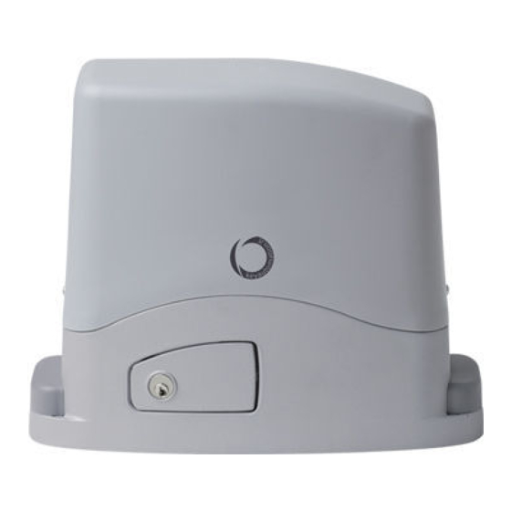
2 - INTRODUZIONE AL PRODOTTO 2.1 - Descrizione del prodotto Motoriduttore elettromeccanico irreversibile per cancelli scorrevoli con alimentazione a 24 Vdc e 230 Vac. 2.2 - Quadro d’insieme e caratteristiche tecniche INSTALLAZIONE STANDARD 1 Colonnina con fotocellula 2 Automazione motoriduttore 3 Fotocellula di rilevazione 4 Lampeggiante di segnalazione 5 Selettore a chiave... - Page 5 DATI TECNICI TURBO 50 TURBO 50 Modello SC-40 SC52 velocità * cm/s coppia ciclo di lavoro centrale di comando CT102 alimentazione Vac (Vdc) assorbimento motore potenza assorbita condensatore µF 12,5 termoprotezione °C grado di protezione dimensione (L - P- H)
-
Page 6: Verifiche Preliminari
3 - VERIFICHE PRELIMINARI Prima di installare il prodotto verificare e controllare i seguenti punti: per evitare il deragliamento del cancello devono essere installate le battute di arresto dello scorrevole, sia in apertura che in chiusura, e la struttura del cancello deve essere solida ed appropriata; un secondo rullo/guida superiore nel pieno rispetto della normativa vigente;... -
Page 7: Fissaggio
4.3 - Fissaggio Togliere il coperchio svitando le viti (fig.5). Appoggiare il motoridut- Qualora la regolazione consentita dalla cremagliera non fosse suf- tore sulla piastra. Inserire le due viti a brugola (fig.6). ficiente, è possibile compensare l’altezza del motoriduttore agendo sulle quattro viti di regolazione (fig.7). -
Page 8: Fissaggio Finecorsa
4.5 - Fissaggio finecorsa Il cancello deve essere dotato di fermi di arresto in apertura e in del peso del cancello, una luce da 30 a 50 mm tra il portone stesso chiusura che impediscano il deragliamento del cancello stesso. e l’arresto meccanico. -
Page 9: Istruzioni Ed Avvertenze Destinate All'utilizzatore Finale
Key Automation non è però il produttore della vostra nare più a lungo possibile ed in completa sicurezza. Concordate automazione, che è invece il risultato di un’opera di analisi, valu- con il vostro installatore un piano di manutenzione con frequenza tazione, scelta dei materiali, e realizzazione dell’impianto eseguita... - Page 10 INDEX Safety warnings pag. 11 Product overview pag. 12 Product description pag. 12 Set panel and technical characteristics pag. 12 Preliminary checks pag. 14 Installing the product pag. 14 Manual running pag. 14 Installing pag. 14 Fixing pag. 15 Rack assembling pag.
- Page 11 The design and manufacture of the devices making up the contact a Key Automation Service Centre. Use of the automation product and the information in this manual are compliant with system in these conditions may cause hazards;...
- Page 12 2 - INTRODUCING THE PRODUCT 2.1 - Product description Irreversible electromechanical gearmotor for sliding gates operating at 24 Vdc and 230 Vac. 2.2 - Set panel and and technical characteristics STANDARD INSTALLATION 1 Post for photocells 2 Automation electromechanical 3 Photocell detectors 4 Flashing light 5 Key switch 6 Radio transmitter...
- Page 13 TECHNICAL DATA TURBO 50 TURBO 50 Model SC-40 SC52 Speed* cm/s Torque Working cycle Control unit CT102 Power Vac (Vdc) Motor consumption Consumption power Capacitor µF 12,5 Thermoprotection °C Protection degree dimension (L - P- H) 320 - 184 - 260...
- Page 14 3 - PRELIMINARY CHECKS Before the installation starts, we suggest to carry out following to avoid the gate derailment you must install the stop beats of the inspections and operations: sliding, whether at the opening or closing, and a second upper roller/runner in full observance of the current law;...
- Page 15 4.3 - Fixing Take the lid off unscrewing the screws (fig.5). Put the gearmotor on If the regulating allowed by the rack is not sufficient, it is possible to the plate. Insert the two socket head screws (fig.6). counterbalance the gearmotor high working on the four screws (fig.7).
- Page 16 4.5 - Limit switch fixing The gate has to be equipped with stop locks at the opening and gate weight, a crack from 30 to 50 mm between the main gate and closing, which prevent the gate derailment. mechanical stop. The stop lock position must assure that the limit switch brackets Fasten the limit switch bracket through the dowels (fig.11) so that don’t collide with the pinion gear.
- Page 17 In the event of safety devices out of ser- Thank you for choosing Key Automation S.r.l.; please visit our Inter- vice arrange for repairs to the automation immediately;...
- Page 18 TABLE DES MATIÈRES Consignes de sécurité page 19 Présentation du produit page 20 Description du produit page 20 Tableau d’ensemble et caractéristiques page 20 techniques Vérifications préalables page 22 Installation du produit page 22 Fonctionnement manuel page 22 Installation page 22 Fixation page 23 Pose de la crémaillère...
-
Page 19: Consignes De Sécurité
ATTENTION - Les données et les informations fournies dans ce structeur, par son service après-vente ou, dans tous les cas, par une guide peuvent être modifiées par Key Automation S.r.l. à tout mo- personne ayant une qualification similaire, de manière à prévenir tout... -
Page 20: Présentation Du Produit
2 - PRÉSENTATION DU PRODUIT 2.1 - Description du produit Motoréducteur électromécanique irréversible pour portails coulissants, alimentation 24 Vdc et 230 Vac. 2.2 - Tableau d’ensemble et caractéristiques techniques INSTALLATION STANDARD 1 Colonnette avec photocellule 2 Motoreducteur 3 Photocellule 4 Clignotante 5 Selecteur à... - Page 21 DONNÉES TECHNIQUES TURBO 50 TURBO 50 Modèle SC-40 SC52 Vitesse* cm/s Couple Cycle de travail Armoire de commande CT102 Alimentation Vac (Vdc) Absorption moteur Puissance absorbée Condensateur µF 12,5 Protection thermique °C Degré de protection Dimensions (L - P- H)
-
Page 22: Vérifications Préalables
3 - VÉRIFICATIONS PRÉALABLES Avant de procéder à l’installation, il est conseillé d’effectuer les pour éviter le déraillement du portail, prévoir les butées de fin de vérifications et opérations suivantes: course (en ouverture et en fermeture) et un deuxième galet sur rail en partie supérieure dans le plein respect de la législation en vigueur;... -
Page 23: Fixation
4.3 - Fixation Retirer le couvercle en dévissant les vis (fig.5). Poser le Si le jeu du réglage de la crémaillère ne devait pas être suffisant, motoréducteur sur la plaque. Insérer les deux vis (fig.6). il serait possible de compenser la hauteur du motoréducteur en agissant sur les quatre vis (fig.7). -
Page 24: Fixation Des Dispositifs De Fin De Course
4.5 - Fixation des dispositifs de fin de course Le portail doit être équipés de 2 butées (en ouverture et en fermeture) du portail, un espace de 30 à 50 mm entre le portail et la butée qui empêchent le déraillement du portail. mécanique. -
Page 25: Instructions Et Avertissements
été débrayé au moyen d’une clé de débrayage fournie avec l’installation. Avec les Nous vous remercions d’avoir choisi Key Automation S.r.l et vous dispositifs de sécurité hors d’usage, il est nécessaire de faire répa- invitons à... - Page 26 ÍNDICE Advertencias para la seguridad pág. 27 Introducción al producto pág. 28 Descripción del producto pág. 28 Figura de conjunto y características técnicas pág. 28 Controles preliminares pág. 30 Instalación del producto pág. 30 Funcionamiento manual pág. 30 Instalación pág. 30 Fijación pág.
- Page 27 ATENCIÓN - Los datos e informaciones indicados en este ma- te la instalación, evite que los líquidos puedan penetrar en el interior nual pueden ser modificados en cualquier momento y sin la de los dispositivos; obligación de preaviso por parte de Key Automation S.r.l.
- Page 28 2 - INTRODUCCIÓN AL PRODUCTO 2.1 - Descripción del producto Motorreductor electromecánico irreversible para puertas correderas con alimentaciones de 24 Vdc y 230 Vac. 2.2 - Figura de conjunto y características técnicas INSTALACIÓN ESTÁNDAR 1 Columna para fotocélula 2 Automatización motorreductor 3 Fotocélulas 4 Lámparas de señalación 5 Selector a llave...
- Page 29 CARACTERÍSTICA TÉCNICAS TURBO 50 TURBO 50 Modelo SC-40 SC52 Velocidad* cm/s Ciclo de trabajo Centrale de mando CT102 Alimentación Vac (Vdc) Absorción motor Potencia absorbida Condensador µF 12,5 Termoproteccion °C Grado de protección Dimensiones (L - A - H) 320 - 184 - 260...
- Page 30 3 - CONTROLES PRELIMINARES Antes de pasar a la instalación se aconseja efectuar los controles y para evitar el descarrilamiento de la reja hay que instalar los topes las operaciones siguientes: del sistema corredero, tanto en la apertura como en el cierre y un segundo rodillo/guía superior en conformidad con la normativa la estructura de la reja debe ser sólida y adecuada;...
- Page 31 4.3 - Fijación Quitar la tapa destornillando los tornillos (fig.5). Apoyar el En caso de que la regulación permitida por la cremallera no fuera motorreductor en la placa. Introducir los dos tornillos allen (fig.6). suficiente, es posible compensar la altura del motorreductor mediante los cuatro tornillos (fig.7).
- Page 32 4.5 - Fijación del fin de carrera La reja debe estar equipada con topes en la apertura y en el cierre la reja, una abertura de 30 a 50 mm entre la misma reja y el tope que impidan el descarrilamiento de la misma reja. mecánico.
- Page 33 Key Automation aconseja un servicio cada 6 meses para un uso lización del sistema realizado por su instalador de confianza. Cada doméstico normal, pero dicha frecuencia puede variar en función...
- Page 34 INHALTSVERZEICHNIS Sicherheitshinweise S. 35 Einführung in das Produkt S. 36 Produktbeschreibung S. 36 S. 36 Bauplan und technische Eigenschaften Vorabkontrollen S. 38 Produktinstallation S. 38 Handbetrieb S. 38 Installation S. 38 Befestigung S. 39 Montage der zahnstange S. 39 Befestigung der anschläge S.
-
Page 35: Sicherheitshinweise
1 - SICHERHEITSHINWEISE ACHTUNG – ORIGINALANWEISUNGEN – Wichtige Die einzelnen Komponenten der Automatisierung dürfen nicht in cherheitsanweisungen. Für die Sicherheit der Personen ist es Wasser oder andere Flüssigkeiten getaucht werden. Bei der In- wichtig, die folgenden Sicherheitsanweisungen zu befolgen. stallation darauf achten, dass keine Flüssigkeit ins Innere der Vor- Bewahren Sie diese Anweisungen auf. -
Page 36: Einführung In Das Produkt
2 - EINFÜHRUNG IN DAS PRODUKT 2.1 - Produktbeschreibung Elektromechanischer irreversibler Getriebemotor für Schiebetore für Versorgung mit 24 Vdc und 230 Vac. 2.2 - Bauplan und technische Eigenschaften STANDARDINSTALLATION 1 Standsäule mit Fotozelle 2 Antriebsautomatisierung 3 Fotozelle zur Erfassung 4 Signal-Blinkleuchte 5 Schlüsseltaster 6 Funksender... - Page 37 TECHNISCHE DATEN TURBO 50 TURBO 50 Modell SC-40 SC52 Geschwindigkeit* cm/s Drehmoment Arbeitszyklus Steuerung CT102 Spannungsversorgung Vac (Vdc) Motorstromaufnahme Leistungsaufnahme Schalten kondensator µF 12,5 Thermoprotektion °C Schutzart Abmessungen (B - T - H) 320 - 184 - 260 320 - 184 - 260...
-
Page 38: Vorabkontrollen
3 - VORABKONTROLLEN Vor der Installation ist folgendes zu beachten: die Torbewegung darf keinerlei Reibungen oder Schwingungen aufweisen; bitte lesen Sie die vorliegenden Anleitungen aufmerksam durch und beachten Sie die vorgegebene Reihenfolge der Arbeitsschritte; die Öffnungs - und Schließbewegung des Garagentores darf ausschließlich mittels Zugkraft/Kompression erfolgen (ohne Kipp - das Gerät darf nicht in Räumen, die brennbare Gase/Flüssigkeiten oder Drehbewegung);... -
Page 39: Befestigung
4.3 - Befestigung Die Schrauben abdrehen und die Abdeckung abnehmen (fig.5). Falls die Einstellung der Zahnstange nicht ausreicht, kann die Höhe Den Torantrieb auf die Platte auflegen. Die zwei Inbusschrauben des Antriebs anhand der vier Schrauben reguliert werden (fig.7). eindrehen (fig.6). Es wird empfohlen, die Schrauben nach einigen Motorbewegungen Es ist wichtig, dass die Inbusschrauben sehr fest angezogen nachzuziehen. -
Page 40: Befestigung Der Anschläge
4.5 - Befestigung der anschläge Das Tor muss mit Anschlägen zur Begrenzung der Öffnungs- und seinem Gewicht - einen Freiraum von 30 bis 50 mm zwischen Tor und Schließbewegung ausgestattet sein, um ein Entgleisen zu Anschlag belassen. verhindern. Den Anschlagbügel mit Stiften befestigen (fig.11), so dass der Die Position des Anschlags ist so zu wählen, dass die Anschlagbügel Mikro-Endschalter gedrückt wird (fig.10). -
Page 41: Anweisungen Und Hinweise Für Den Endbenutzer
Schlüssel, der zum Lieferumfang gehört, wie eine nicht automatisierte Öffnung arbeiten. Bei nicht funktionierenden Wir danken Ihnen, dass Sie Key Automation S.r.l. gewählt haben, Sicherheitsvorrichtungen muss schnellstmöglich die Reparatur der und laden Sie ein, für weitere Informationen unsere Internetseite Automation veranlasst werden;... - Page 42 ÍNDICE Avisos sobre a segurança pag. 43 Informações sobre o produto pag. 44 Descrição do produto pag. 44 Quadro de conjunto e características técnicas pag. 44 Controlos preliminares pag. 46 Instalação do produto pag. 46 Funcionamento manual pag. 46 Instalação pag.
- Page 43 É importante para a segurança das pesso- da automação, desligar de imediato a alimentação elétrica e con- as observar as seguintes instruções de segurança. Conservar tactar o serviço de Assistência Key Automation. A utilização da au- estas instruções. tomação nestas condições pode causar situações de perigo.
-
Page 44: Informações Sobre O Produto
2 - INFORMAÇÕES SOBRE O PRODUTO 2.1 - Descrição do produto Motorredutor eletromecânico irreversível para portões de correr com alimentação de 24 Vdc e 230 Vac. 2.2 - Quadro de conjunto e características técnicas INSTALAÇÃO PADRÃO 1 Coluna com fotocélula 2 Automação do motorredutor 3 Fotocélula de deteção 4 Luz de sinalização... - Page 45 DADOS TÉCNICOS TURBO 50 TURBO 50 Modelo SC-40 SC52 Velocidade* cm/s Binário Ciclo de trabalho Unidade CT102 Alimentação Vac (Vdc) Absorção do motor Potência absorvida Condensador µF 12,5 Protecção térmica °C Grau de proteção Dimensões (compr. - prof. - alt.)
-
Page 46: Controlos Preliminares
3 - CONTROLOS PRELIMINARES Antes de proceder à instalação propriamente dita, aconselhamos a para evitar o descarrilamento do portão, é preciso instalar os efectuar as seguintes verificações e operações: batentes de paragem do portão de correr, quer para a abertura, quer para o fecho, e um segundo rolo/guia respeitando plenamente a estrutura do portão deve ser sólida e apropriada;... -
Page 47: Fixação
4.3 - Fixação Tire a tampa desapertando os parafusos (fig.5). Apoie o motorredutor Se a regulação permitida pela cremalheira não for suficiente, é na chapa. Introduza os dois parafusos Allen (fig.6). possível compensar a altura do motorredutor ajustando os quatro parafusos (fig.7). -
Page 48: Fixação Dos Fins De Curso
4.5 - Fixação dos fins de curso O portão deve ter batentes de paragem para a abertura e para o paragem mecânico. fecho, capazes de impedir o descarrilamento dele. Fixe o estribo do fim de curso com os parafusos sem cabeça A posição do batente de paragem deve impedir que os estribos de (fig.11) de maneira que o microinterruptor de fim de curso seja fim de curso se choquem contra o pinhão. -
Page 49: Instruções E Avisos Para O Utilizador Final
Key Automation recomenda uma intervenção a cada 6 meses feita pelo seu instalador de confiança. Cada automação é única e para uma utilização doméstica normal, mas este período pode va-... - Page 50 SPIS TREŚCI Uwagi dotyczące bezpieczeństwa str. 51 Informacje wstępne o produkcie str. 52 Opis produkcie str. 52 Konfiguracja panelu i parametry techniczne str. 52 Kontrole wstępne str. 54 Montaż produktu str. 54 Obsługa ręczna str. 54 Instalacja str. 54 Mocowanie str.
- Page 51 UWAGA – dane oraz informacje zawarte w niniejszej instrukcji powinien on zostać wymieniony przez producenta, autoryzowany mogą ulegać zmianom, bez obowiązku powiadamiania o tym serwis techniczny lub przez osobę posiadającą odpowiednie kwali- fakcie przez Key Automation S.r.l.
-
Page 52: Informacje Wstępne O Produkcie
2 - INFORMACJE WSTĘPNE O PRODUKCIE 2.1 - Opis produkcie Nienawrotny motoreduktor elektromechaniczny do bram przesuwnych, zasilanie 24 VDC i 230 VAC. 2.2 - Konfiguracja panelu i parametry techniczne MONTAŻ STANDARDOWY 1. Słupek z fotokomórką 2. Napęd motoreduktora 3. Fotokomórka wykrywająca 4. - Page 53 PARAMETRY TECHNICZNE TURBO 50 TURBO 50 Model SC-40 SC52 Prędkość* cm/s Moment obrotowy Cykl pracy Centrala CT102 Zasilanie Vac (Vdc) Pobór prądu silnika Moc pobierana Kondensator µF 12,5 Zabezpieczenie termalne °C Stopień ochrony Wymiary (D – S – W) 320 - 184 - 260...
-
Page 54: Kontrole Wstępne
3 - KONTROLE WSTĘPNE Przed przystąpieniem instalacji zaleca się wykonanie aby zapobiec wykolejeniu się bramy, należy zainstalować, przy następujących czynności i inspekcji: otwarciu lub zamknięciu, stopki zatrzymujące ruch bramy oraz dodatkowe rolki/prowadnicę zgodnie z obowiązującymi przepisami; struktura bramy musi być mocna i odbowiednia; usuń... -
Page 55: Mocowanie
4.3 - Mocowanie Zdejmij pokrywę, odkręcając wkręty (fig.5). Połóż napęd silnikowy Jeśli regulacja dozwolona przez listwę jest niewystarczająca, na płytę. Wstaw obydwa wkręty z łbem gniazdowym (fig.6). możesz zrównoważyć wysokość napędu, korzystając z czterech wkrętów (fig.7). Pamiętaj, aby mocno zablokować obydwa wkręty, upewniając się, że napęd jest mocno przymocowany do powierzchni w trakcie Zalecane jest ponowne dokręcenie śrub po wykonaniu kilku cykli całego ruchu bramy. -
Page 56: Mocowanie Wyłącznika Krańcowego
4.5 - Mocowanie wyłącznika krańcowego Brama musi być wyposażona w dwa zamki blokujące przy otwarciu wymiarach od 30 do 50mm, w zależności od ciężaru bramy, i zamknięciu, aby zapobiec jej wykolejeniu się. pomiędzy bramą główną i hamulcem mechanicznym. Położenie zamków blokujących musi zapewnić, że wsporniki Przymocuj wspornik wyłącznika krańcowego za pomocą... -
Page 57: Instrukcje I Ostrzeżenia Dla Użytkownika Końcowego
• Ręczne odblokowanie i przesunięcie. Przed przystąpieniem do bram ogrodzeniowych i garażowych, drzwi automatycznych, rolet wykonania tej czynności należy upewnić się, że skrzydło bramy po- oraz szlabanów parkingowych i drogowych. Key Automation nie jest zostaje nieruchome. jednakże wykonawcą Państwa całościowego systemu automatyki, który stanowi wynik analizy, oceny, doboru materiałów i wykonania... - Page 58 UWAGI...
-
Page 59: Déclaration Ce De Conformité
DICHIARAZIONE DI INCORPORAZIONE DI QUASI-MACCHINA DECLARATION OF INCORPORATION OF PARTLY COMPLETED MACHINERY Il sottoscritto Nicola Michelin, Amministratore Delegato dell’azienda The undersigned Nicola Michelin, General Manager of the company Key Automation srl, Via Alessandro Volta, 30 - 30020 Noventa di Piave (VE) – ITALIA dichiara che il prodotto tipo: declares that the product type: TURBO Motoriduttore elettromeccanico irreversibile per cancelli scorrevoli da 300Kg a 2500Kg Electromechanical irreversible gear motor for sliding gates from 300Kg to 2500Kg ... - Page 60 Key Automation S.r.l. Via A. Volta 30 - 30020 Noventa di Piave (VE) T. +39 0421.307.456 - F. +39 0421.656.98 Instruction version info@keyautomation.it - www.keyautomation.it 580ISSC-50 REV.06...