Champion RANGE AND TARGET WHEELYBIRD 2.0 Mode D'emploi

Lanceur de pigeons d'argile à chargement automatique
Table des Matières

Publicité

Les langues disponibles

Les langues disponibles

Liens rapides

WHEELYBIRD 2.0™
AUTO-FEED TRAP
Part No. 40925
Instruction Manual
WARNING: THIS MACHINE CAN CAUSE SERIOUS INJURY OR DEATH !
THOROUGHLY READ INSTRUCTIONS BEFORE INSTALLING OR OPERATING TRAP !

Publicité

Chapitres

Table des Matières
loading

Sommaire des Matières pour Champion RANGE AND TARGET WHEELYBIRD 2.0

  • Page 1 WHEELYBIRD 2.0™ AUTO-FEED TRAP Part No. 40925 Instruction Manual WARNING: THIS MACHINE CAN CAUSE SERIOUS INJURY OR DEATH ! THOROUGHLY READ INSTRUCTIONS BEFORE INSTALLING OR OPERATING TRAP !
  • Page 2 ENGLISH 3-29 FRANÇAIS 30-56...
  • Page 3: Table Des Matières

    Table of Contents Section Page Introduction Safety III. Tools Required for Assembly Assembly and Installation (A) Unpacking (B) Contents (C) Assembly Assemble Frame Attach Trap to Frame Attach Throwing Arm Path Indicator Attach Magazine Assembly Install Mainspring Setup Operation Adjustments (A) Throwing Arm Limit Switch (B) Elevation Adjustment (C) Distance Adjustment...
  • Page 4: Introduction

    I. Introduction The WHEELYBIRD 2.0™ Auto-Feed Trap is designed for the active sporting clays, trap, and skeet shooter looking for an automatic, lightweight, and portable machine for practice/ fun shooting. Features and benefits of the WHEELYBIRD 2.0™ Auto-Feed Trap: Safety •...
  • Page 5: Safety

    II. Safety WARNING: THOROUGHLY READ ALL INSTRUCTIONS, WARNINGS, CAUTIONS AND SAFETY INFORMATION BEFORE INSTALLING OR OPERATING THE TRAP. FAILURE TO READ AND FOLLOW THESE INSTRUCTIONS COULD RESULT IN SERIOUS PERSONAL INJURY OR DEATH. DO NOT STAND IN FRONT OF THE TRAP WHEN IT IS IN THE COCKED POSITION. SERIOUS INJURY OR DEATH CAN RESULT.
  • Page 6 WARNING: BEFORE PERFORMING ANY REPAIR, MAINTENANCE, OR ASSEMBLY, MAKE SURE THE THROWING ARM IS IN THE UNCOCKED POSITION (SEE BELOW), THE ON/OFF/SAFE RELEASE SWITCH LOCATED ON THE REAR OF THE TRAP IS IN THE ‘OFF‘ POSITION (SEE BELOW), THE BATTERY IS DISCONNECTED FROM THE TRAP AND THE MAIN SPRING IS DISENGAGED.
  • Page 7: Tools Required For Assembly

    2. Carefully remove trap assembly and all other components from cardboard shipping box and other smaller boxes. Remove all hardware from bags. 3. Check that all parts were included. If any parts are missing, call the CHAMPION Customer Service Department at (800) 379-1732 to obtain replacement parts.
  • Page 8: (B) Contents

    (B) Contents Trap Assembly Frame Legs Parts (not shown to scale) F1 - Axle F2 - Bracket Support Bar F3 - Handle F4 - 8mm x 45mm Bolt (4) F5 - 8mm x 16mm Bolt (2) F6 - 8mm Washer (12) F7 - 8mm Lock Nut (6) F8 - Wheel (2) F9 - Axle Clip (2)
  • Page 9 (B) Contents (con’t) Mainspring Assembly S1 - Mainspring S2 - Mainspring Bolt S3 - Bushing S4 - Handnut Throwing Arm Path Indicator Tubing Parts A1 - Throwing Arm Path Indicator Tube Support (2) A2 - Throwing Arm Path Indicator Tube Stud (2) A3 - Throwing Arm Path Tubing Magazine Parts M1 - Magazine Rods (4)
  • Page 10: (C) Assembly

    (C) Assembly CAUTION: PROVIDE AMPLE CLEARANCE AROUND THE TRAP. DO NOT OPERATE THE TRAP IN AN AREA THAT DOES NOT ALLOW SAFE (REAR) ACCESS TO THE TRAP AND THE ON/OFF/SAFE RELEASE SWITCH DURING LOADING AND USE. Assemble Frame 1. Assemble Axle (F1) and Bracket Support Bar (F2) to Mounting Bracket (F10) using 8mm x 45mm Bolt (F4), 8mm x 16mm bolt (F5) with 8mm Washers (F6) and 8mm Lock Nut (F7).
  • Page 11: Attach Trap To Frame

    (C) Assembly (con’t) Attach Trap to Frame 1. Stand and support trap assembly on front panel as shown. 2. Attach Mounting Bracket (F10) to trap using 10mm x 16mm Bolt (F11) and 10mm Washer (F12) as shown. 3. Pivot trap and frame back when finished. F11 F12...
  • Page 12: Attach Throwing Arm Path Indicator

    (C) Assembly (con’t) Attach Throwing Arm Path Indicator 1. Attach Throwing Arm Path Indicator Tube Support (A1) to each front side of trap by threading arm path tube support into chassis. 2. Thread Throwing Arm Path Indicator Tube Stud (A2) into each rear tapped side hole of trap and tighten securely.
  • Page 13: Attach Magazine Assembly

    Attach Magazine Assembly 1. Slide Magazine Rod (M1) over each magazine stud as shown. 2. Attach Magazine Top Plate (M2) using 5mm x 10mm Screws (M3) and 5mm Lock Washers (M4). Opening of Magazine Top Plate (M2) should be toward rear of trap. Rear of Machine Magazine Rods Magazine Top Plate...
  • Page 14: Setup

    5. Attach S3 (Bushing) and S4 (Handnut) to S2 (Mainspring Bolt). 6. With the throwing arm still facing forward of the trap, tighten S4 (Handnut) until all the slack is taken up in the spring and the bolt is tight. Setup WARNING: MAKE SURE THAT THE “ON-OFF-SAFE RELEASE”...
  • Page 15: Operation

    V. Operation WARNING: DO NOT STAND IN FRONT OF TRAP OR IN THE PATH OF THE THROWING ARM! SERIOUS INJURY OR DEATH MAY RESULT! 1. The throwing arm path indicator must be mounted properly before using trap. 2. Make sure that the trap is located to allow ample clearance around machine and provides safe access to the rear of the trap during operation.
  • Page 16: Adjustments

    VI. Adjustments (A) Throwing Arm Limit Switch WARNING: BEFORE MAKING ANY ADJUSTMENTS, MAKE SURE THE THROWING ARM IS IN THE UNCOCKED POSITION, THE ON/OFF/SAFE RELEASE SWITCH IS IN THE “OFF” POSITION, AND THE BATTERY IS DISCONNECTED FROM THE TRAP! DO NOT MANUALLY FORCE THE THROWING ARM THROUGH THE UNCOCKED POSITION AS THE MAIN SPRING WILL TAKE OVER AND FIRE THE TRAP, POTENTIALLY CAUSING SERIOUS INJURY OR DEATH.
  • Page 17 Adjustments to the limit switch are made by loosening the two mounting screws and moving the switch slightly (small movements will make a big difference): 1. Pivot the switch slightly towards the rear of the trap to make the arm stop further away from the edge of the main body.
  • Page 18: (B) Elevation Adjustment

    (B) Elevation Adjustment WARNING: BEFORE MAKING ANY ADJUSTMENTS, MAKE SURE THE THROWING ARM IS IN THE UNCOCKED POSITION, THE ON/OFF/SAFE RELEASE SWITCH IS IN THE “OFF” POSITION, AND THE BATTERY IS DISCONNECTED FROM THE TRAP. DO NOT MANUALLY FORCE THE THROWING ARM THROUGH THE UNCOCKED POSITION AS THE MAIN SPRING WILL TAKE OVER AND FIRE THE TRAP, POTENTIALLY CAUSING SERIOUS INJURY OR DEATH.
  • Page 19: (C) Distance Adjustment

    (C) Distance Adjustment WARNING: BEFORE MAKING ANY ADJUSTMENTS, MAKE SURE THE THROWING ARM IS IN THE UNCOCKED POSITION, THE ON/OFF/SAFE RELEASE SWITCH IS IN THE “OFF” POSITION, AND THE BATTERY IS DISCONNECTED FROM THE TRAP. THIS TRAP IS CAPABLE OF THROWING TARGETS A DISTANCE OF UP TO 75 YARDS.
  • Page 20: Transportation And Storage

    VII. Transportation and Storage WARNING: BEFORE MAKING ANY ADJUSTMENTS, MAKE SURE THE THROWING ARM IS IN THE UNCOCKED POSITION, THE ON/OFF/SAFE RELEASE SWITCH IS IN THE “OFF” POSITION, AND THE BATTERY IS DISCONNECTED FROM THE TRAP. UNINTENTIONAL FIRING OF THE TRAP CAN CAUSE INJURY OR DEATH FROM BEING STRUCK BY THE THROWING ARM.
  • Page 21: Troubleshooting

    VIII. Troubleshooting THE MOTOR WILL NOT START 1. The “ON-OFF-SAFE RELEASE” switch on the trap is in the “OFF” position. 2. Circuit breaker on rear of trap is tripped - determine cause before resetting. 3. Battery is inadequately charged - recharge battery. 4.
  • Page 22: Maintenance

    SAFETY FEATURES ARE IN GOOD CONDITION AND THAT THE TRAP IS FREE OF DEBRIS BEFORE EVERY USE. FAILURE TO PROPERLY MAINTAIN THIS PRODUCT COULD INCREASE RISK OF DEATH OR SERIOUS INJURY. X. Replacement Parts Parts are available by calling Champion Customer Service Department at (800) 379-1732.
  • Page 23: Appendix: Wireless Remote Accessory Instructions

    XI. Appendix: Wireless Remote Accessory Instructions WARNING: TO AVOID SERIOUS INJURY OR PROPERTY DAMAGE, THOROUGHLY READ INSTRUCTIONS BEFORE USING. Features of the Champion Wireless Remote ® Release system include: • Battery powered hand-held remote, high impact plastic case • Long transmission range •...
  • Page 24 Safety • Do not stand in front of the trap when it is in the cocked position. Accidental release of the target and/or throwing arm can cause serious injury or death! • Before installing the Wireless Receiver on the trap, make sure that the throwing arm is in the uncocked position, the trap is in the off position and the trap is disconnected from the battery.
  • Page 25 Features and Descriptions Wireless Receiver A) Remote Learn Button • Initiates pairing (programming) of Receiver and Wireless Remote Transmitter. B) Remote Learn Light • Flashes slowly to indicate the Receiver is ready to learn the Wireless Remote Transmitter. • Flashes rapidly three times when Receiver has learned the Wireless Remote Transmitter to confirm the signal has been received.
  • Page 26: Mounting The Receiver

    Installation WARNING: MAKE SURE THAT THE THROWING ARM IS IN THE UNCOCKED POSITION, THE TRAP IS IN THE OFF POSITION, THE MAINSPRING IS REMOVED, AND THE TRAP IS DISCONNECTED FROM THE BATTERY. FOOT PEDAL MUST BE REMOVED FROM TRAP BEFORE USING REMOTE TRANSMITTER/RECEIVER TO ACTIVATE THE TRAP.
  • Page 27 3. Set trap main power switch to “ON”. Receiver Status Light (C) will light up green to indicate the Receiver is activated and ready to receive signals from the Transmitter. 4. Repeat above steps 1- 3 for additional traps/Receivers if operating multiple traps from the transmitter.
  • Page 28: Warranty Card/Certificate

    LIMITATIONS ON INCIDENTAL, OR CONSEQUENTIAL DAMAGES, SO THE ABOVE LIMITATION OR EXCLUSION MAY NOT APPLY TO YOU. The above warranty provides the sole and exclusive warranty available to the customer in the event of a defect in material or workmanship in the CHAMPION WHEELYBIRD 2.0™...
  • Page 29: Contact Information

    XIII. CONTACT INFORMATION Champion Traps and Targets 9200 Cody Overland Park, KS 66214 Toll Free: (800) 379-1732 Internet: www.championtarget.com Email: tech.expert@vistaoutdoor.com...
  • Page 30 Table des matières Section Page Introduction Sécurité III. Outils nécessaires pour l’assemblage Assemblage et installation (A) Déballage (B) Contenu (C) Assemblage Assembler la structure Fixer le lanceur à la structure Fixer l’indicateur de trajectoire du bras de lancement Fixer l’assemblage du chargeur Installer le grand ressort Configuration Utilisation...
  • Page 31: Introduction

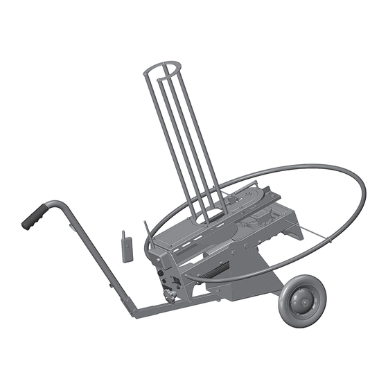
    I. Introduction Le lanceur de pigeons d’argile à chargement automatique WHEELYBIRD 2.0™ est conçu pour les tireurs sportifs d’argiles, de pigeons d’argile, aux plateaux et au skeet, qui recherchent un dispositif automatique, léger et portatif pour pratiquer le tir et s’amuser. Caractéristiques et avantages du lanceur de pigeons d’argile à...
  • Page 32: Sécurité

    II. Sécurité AVERTISSEMENT : LIRE ATTENTIVEMENT TOUTES LES INSTRUCTIONS, MISES EN GAR- DE, INFORMATIONS DE SÉCURITÉ ET TOUS LES AVERTISSEMENTS AVANT D’INSTALL- ER OU D’UTILISER LE LANCEUR. LE FAIT DE NE PAS LIRE ET DE NE PAS SUIVRE CES IN- STRUCTIONS POURRAIT ENTRAÎNER DES BLESSURES GRAVES OU LA MORT. NE PAS SE TENIR DEVANT LE LANCEUR DE PIGEONS D’ARGILE LORSQU’IL EST EN POSITION ARMÉE.
  • Page 33 AVERTISSEMENT  : AVANT D’EFFECTUER RÉPARATION, ENTRETIEN OU ASSEMBLAGE, S’AS- SURER QUE LE BRAS DE LANCEMENT EST EN POSITION DÉSARMÉE (VOIR CI-DESSOUS), QUE L’INTERRUPTEUR DE DÉCLENCHEMENT«  ON/OFF/SAFE RELEASE  » SITUÉ À  L’AR- RIÈRE DU LANCEUR EST EN POSITION ’OFF’ (VOIR CI-DESSOUS ), QUE LA BATTERIE EST DÉCONNECTÉE DU LANCEUR ET QUE LE GRAND RESSORT EST DÉSENGAGÉ.
  • Page 34: Outils Nécessaires Pour L'assemblage

    Retirer tout le matériel des sacs. 3. Vérifier qu’aucune pièce n’est manquante. Si des pièces manquent, contacter service à la cli- entèle de CHAMPION au 800 379-1732 pour obtenir celles-ci. 4. Conserver tout le matériel et la boîte d’emballage pour la réutiliser dans l’éventualité où le lan-...
  • Page 35: (B) Contenu

    (B) Contenu Ensemble de lanceur Pièces de la structure de pieds (non illustrées à l’échelle) F1 – Essieu F2 – Barre de support F3 – Poignée F4 – Boulon de 8 mm x 45 mm (4) F5 – Boulon de 8 mm x 16 mm (2) F6 – Rondelle de 8 mm (12) F7 –...
  • Page 36: Assemblage Du Grand Ressort

    (B) Contenu (suite) Assemblage du grand ressort S1 – Grand ressort S2 – Boulon de grand ressort S3 – Bague S4 – Écrou Pièces du tube d’indicateur de la trajectoire du bras de lancement A1 – Support de tube indicateur de trajectoire du bras de lancement (2) A2 –...
  • Page 37: (C) Assemblage

    (C) Assemblage MISE EN GARDE : LAISSER UN ESPACE SUFFISAMMENT LIBRE AUTOUR DU LANCEUR. NE PAS FAIRE FONCTIONNER LE LANCEUR DANS UN ENDROIT QUI N’OFFRE PAS UN ACCÈS SÉCURITAIRE À L’ARRIÈRE DE L’APPAREIL ET À L’INTERRUPTEUR DE DÉCLENCHE- MENT « ON/OFF/SAFE RELEASE » PENDANT LE CHARGEMENT ET L’UTILISATION. Assembler la structure 1.
  • Page 38: Fixer Le Lanceur À La Structure

    (C) Assemblage (suite) Fixer le lanceur à la structure 1. Installer et retenir le lanceur sur le panneau avant comme le montre l’illustration. 2. Fixer le support de montage (F10) au lanceur à l’aide d’un boulon de 10 mm x 16 mm (F11) et d’une rondelle de 10 mm (F12) comme illustré.
  • Page 39: Fixer L'indicateur De Trajectoire Du Bras De Lancement

    (C) Assemblage (suite) Fixer l’indicateur de trajectoire du bras de lancement 1. Fixer le support du tube de l’indicateur de trajectoire du bras de lancement (A1) de chaque côté avant du lanceur en insérant le support du tube de trajectoire du bras dans le châssis. 2.
  • Page 40: Fixer L'assemblage Du Chargeur

    Fixer l’assemblage du chargeur 1. Faire glisser la tige du chargeur (M1) sur chaque goujon du chargeur comme indiqué. 2. Fixer la plaque supérieure du chargeur (M2) à l’aide des vis de 5 mm x 10 mm (M3) et des rondelles de blocage de 5 mm (M4). L’ouverture de la plaque supérieure du chargeur (M2) doit être dirigée vers l’arrière du lanceur.
  • Page 41: Configuration

    5. Fixer S3 (douille) et S4 (écrou) au S2 (boulon du grand ressort). 6. Avec le bras de lancement toujours tourné vers l’avant du lanceur, serrer S4 (écrou) jusqu’à ce que tout l’écart soit comblé dans le ressort et le boulon bien serré. Configuration AVERTISSEMENT : S’ASSURER QUE L’INTERRUPTEUR DE DÉCLENCHEMENT « ON-OFF-SAFE »...
  • Page 42: Utilisation

    V. Utilisation AVERTISSEMENT : NE PAS SE TENIR DEVANT LE LANCEUR OU DANS LA TRAJECTOIRE DU BRAS DE LANCEMENT! LE NON-RESPECT DE CETTE RÈGLE PET ENTRAÎNER DES BLESSURES GRAVES OU MÊME LA MORT! 1. L’indicateur de trajectoire du bras de lancement doit être correctement monté avant d’utiliser le lanceur.
  • Page 43: Réglages

    VI. Réglages (A) Interrupteur de fin de course du bras de lancement AVERTISSEMENT : AVANT D’EFFECTUER LES RÉGLAGES, S’ASSURER QUE LE BRAS DE LANCEMENT EST EN POSITION DÉSARMÉE, QUE L’INTERRUPTEUR DE DÉCLENCHE- MENT « ON/OFF/SAFE RELEASE » EST EN POSITION « OFF », ET QUE LA BATTERIE EST DÉBRANCHÉE DU LANCEUR! NE PAS FORCER MANUELLEMENT LE BRAS DE LANCE- MENT POUR LE METTRE EN POSITION DÉSARMÉE CAR LE GRAND RESSORT PRENDRA LE RELAIS POUR DÉCLENCHER LE LANCEUR, CAUSANT POTENTIELLEMENT DES BLES-...
  • Page 44 Les réglages de l’interrupteur de fin de course se font en desserrant les deux vis de fixation et en déplaçant légèrement l’interrupteur (de petits mouvements feront une grande différence) : 1. Faire pivoter l’interrupteur légèrement vers l’arrière du lanceur pour faire en sorte que le bras s’arrête en étant plus éloigné...
  • Page 45: (B) Réglage De L'altitude

    (B) Réglage de l’altitude AVERTISSEMENT  : AVANT D’EFFECTUER LES RÉGLAGES, S’ASSURER QUE LE BRAS  DE  LANCEMENT EST EN POSITION DÉSARMÉE, QUE L’INTERRUPTEUR DE DÉCLENCHEMENT « ON/OFF/SAFE RELEASE » EST EN POSITION « OFF », ET QUE LA BATTERIE EST DÉBRANCHÉE DU LANCEUR. NE PAS FORCER MANUELLEMENT LE ...
  • Page 46: (C) Réglage De La Distance

    (C) Réglage de la distance AVERTISSEMENT  : AVANT D’EFFECTUER LES RÉGLAGES, S’ASSURER QUE LE BRAS DE LANCEMENT EST EN POSITION DÉSARMÉE, QUE L’INTERRUPTEUR DE DÉ- CLENCHEMENT « ON/OFF/SAFE RELEASE » EST EN POSITION « OFF », ET QUE LA BAT- TERIE EST DÉBRANCHÉE DU LANCEUR. CE LANCEUR EST CAPABLE DE PROJETER DES CIBLES À...
  • Page 47: Transport Et Entreposage

    VII. Transport et entreposage AVERTISSEMENT  : AVANT D’EFFECTUER LES RÉGLAGES, S’ASSURER QUE LE BRAS  DE  LANCEMENT EST EN POSITION DÉSARMÉE, QUE L’INTERRUPTEUR DE DÉCLENCHEMENT «  ON/OFF/SAFE RELEASE  » EST EN POSITION «  OFF  », ET QUE LA BATTERIE EST DÉBRANCHÉE DU LANCEUR. LE DÉCLENCHEMENT NON INTENTIONNEL DU LANCEUR PEUT CAUSER DES BLESSURES, VOIRE LA MORT, SI L’ON SE FAIT FRAPPER PAR LE BRAS DE LANCEMENT.
  • Page 48: Dépannage

    VIII. Dépannage LE MOTEUR NE DÉMARRE PAS 1. L’interrupteur « ON-OFF-SAFE RELEASE » sur le lanceur est en position « OFF ». 2. Le disjoncteur à l’arrière du lanceur est déclenché. Il faut en déterminer la cause avant de le réinitialiser. 3. La batterie n’est pas suffisamment chargée. La recharge de la batterie est nécessaire. 4.
  • Page 49: Entretien

    DISPOSITIFS DE SÉCURITÉ SONT EN BON ÉTAT ET QUE LE LANCEUR EST DÉPOURVU DE DÉBRIS AVANT CHAQUE UTILISATION. L’ENTRETIEN INADÉQUAT DU PRODUIT PEUT AUGMENTER LES RISQUES DE BLESSURES GRAVES, VOIRE DE MORT. X. Pièces de rechange Les pièces sont disponibles en contactant le service à la clientèle de Champion au 800 379-1732.
  • Page 50: Annexe : Instructions Sur Les Accessoires De Télécommande Sans Fil

    XI. Annexe : Instructions sur les accessoires de télécommande sans fil AVERTISSEMENT : POUR ÉVITER BLESSURES ET DÉGÂTS MATÉRIELS, LIRE ATTENTIVEMENT LES INSTRUCTIONS AVANT L’UTILISATION. Les fonctionnalités de ce mécanisme de déclenchement sans fil Champion incluent : ® • Télécommande portable à batterie, boîtier en plastique résistant...
  • Page 51 Sécurité • Ne pas se tenir devant le lanceur de pigeons d’argile lorsqu’il est en position armée. Le déclenchement non intentionnel du lanceur ou du bras de lancement peut causer des blessures graves ou même la mort! • Avant d’installer le récepteur sans fil sur le lanceur de pigeon d’argile, s’assurer que le bras de lancement est en position désarmée, que le lanceur est sur la position arrêt et débranché...
  • Page 52: Fonctionnalités Et Descriptions

    Fonctionnalités et descriptions Récepteur sans fil A) Bouton [Learn] de la télécommande • Lance l’appariement (programmation) du récepteur et de l’émetteur à distance sans fil. B) Témoin [Learn] de la télécommande • Clignote lentement pour indiquer que le récepteur est prêt à se jumeler à l’émetteur à distance sans fil.
  • Page 53: Montage Du Récepteur

    Installation AVERTISSEMENT : S’ASSURER QUE LE BRAS DE LANCEMENT EST EN POSITION DÉSARMÉE, QUE LE LANCEUR EST EN POSITION « OFF », QUE LE GRAND RESSORT EST RETIRÉ ET QUE LE LANCEUR EST DÉBRANCHÉ DE LA BATTERIE. LA PÉDALE DOIT ÊTRE RETIRÉE DU LANCEUR AVANT D’UTILISER L’ÉMETTEUR/RÉCEPTEUR À DISTANCE POUR ACTIVER LE LANCEUR.
  • Page 54 3. Placer l’interrupteur principal en position « ON ». Le témoin de statut du récepteur (C) s’allume en vert pour indiquer que le récepteur est activé et prêt à recevoir les signaux de l’émetteur. 4. Répéter les étapes 1 à 3 ci-dessus pour des lanceurs et récepteurs supplémentaires si plusieurs lanceurs sont utilisés à...
  • Page 55: Carte De Garantie

    La garantie ci-dessus représente la seule et unique garantie valable pour le client en cas de défaut de matériau ou de fabrication pour le LANCEUR DE PIGEONS D’ARGILE À CHARGEMENT AUTOMATIQUE CHAMPION WHEELYBIRD 2.0™. Cette garantie vous accorde des droits juridiques particuliers, mais vous pouvez également avoir d’autres droits qui varient selon les États et les provinces.
  • Page 56: Coordonnées

    XIII. Coordonnées Champion Traps and Targets 9200 Cody Overland Park, KS 66214 Sans frais : 800 379-1732 Internet : www.championtarget.com Courriel : tech.expert@vistaoutdoor.com...
  • Page 57 Champion Traps and Targets 9200 Cody Overland Park, KS 66214 Toll Free: (800) 379-1732 Internet: www.championtarget.com Email: tech.expert@vistaoutdoor.com PRINTED IN CHINA MADE IN CHINA 1/12/18...

Ce manuel est également adapté pour:

40925604544631210

Table des Matières