Warn 83405 Instructions De Montage
Kit de montage pour treuil de vtt. méthode d'application: 2009 honda big red
Table des Matières
Les langues disponibles
Les langues disponibles
Liens rapides
Your safety, and the safety of others, is very important. To help you make informed decisions about
safety, we have provided installation and operating instructions and other information on labels and in
this guide. This information alerts you to potential hazards that could hurt you or others. It is not possible
to warn you about all potential hazards associated with this product, you must use your own good judg-
ment.
CARELESS INSTALLATION AND OPERATION CAN RESULT IN SERIOUS INJURY OR EQUIPMENT
DAMAGE. READ AND UNDERSTAND ALL SAFETY PRECAUTIONS AND OPERATING INSTRUC-
TIONS BEFORE INSTALLING AND OPERATING THIS PRODUCT.
This guide identifies potential hazards and has important safety messages that help you and others avoid
personal injury or death. WARNING and CAUTION are signal words that identify the level of hazard. These
signal words mean:
WARNING signals a hazard that could cause serious injury or death, if you do not follow recom-
mendations.
CAUTION signals a hazard that may cause minor to moderate injury, if you do not
follow recommendations.
This guide uses NOTICE to call attention to important mechanical information, and Note: to emphasize
general information worthy of special attention.
Failure to observe these instructions could lead to severe injury or death.
Always use extreme caution when drilling on any vehicle. Make sure that all fuel lines, brake lines, electrical
wires, and other objects are not punctured or damaged when / if drilling on the vehicle. Thoroughly inspect
the area to be drilled (on both sides of material) prior to drilling, and relocate any objects that may be dam-
aged. Failure to inspect the area to be drilled may result in vehicle damage, electrical shock, fire or personal
injury.
Always wear safety glasses when installing this kit. A drilling operation will cause flying metal chips. Flying
chips can cause eye injury.
Always use extreme caution when cutting and trimming during fitting.
Always remove jewelry and wear eye protection.
Never lean over battery while making connections.
Never route electrical cables:
Across any sharp edges.
Through or near moving parts.
Near parts that become hot.
Always insulate and protect all exposed wiring and electrical terminals.
Always install terminal boots as directed in installation instructions.
Always use appropriate and adequate care in lifting components into place.
Always insure components will remain secure during installation and operation.
Always tighten all nuts and bolts securely, per the installation and operation.
Always perform regular inspections and maintenance on the winch, winch mount and related hardware.
Never operate this WARN product with damaged or missing parts.
INSTALLATION INSTRUCTIONS
WINCH MOUNTING KIT
Part Number: 83405
Application: 2009-2010 Honda Big Red
WARNING
INJURY HAZARD
PAGE 1
83406A0
Table des Matières

Manuels Connexes pour Warn 83405


Sommaire des Matières pour Warn 83405
-
Page 11: Kit De Montage Pour Treuil De Vtt
Serrez toujours bien les écrous et les boulons conformément aux instructions d’installation et d’utilisation. Effectuez toujours régulièrement les inspections et l’entretien du treuil, de son kit de montage et du matériel de montage connexe. Ne faites jamais fonctionner ce produit WARN avec des pièces endommagées ou manquantes. PAGE 11 83406A0... -
Page 12: Avant De Commencer
Reportez-vous toujours au Guide d’installation et de spécification, fourni dans le kit de treuil, pour tous les schémas de câblage et des informations détaillées concernant la façon de brancher ce produit WARN sur votre véhicule. Veuillez lire attentivement les instructions concernant l’installation et l’utilisation. -
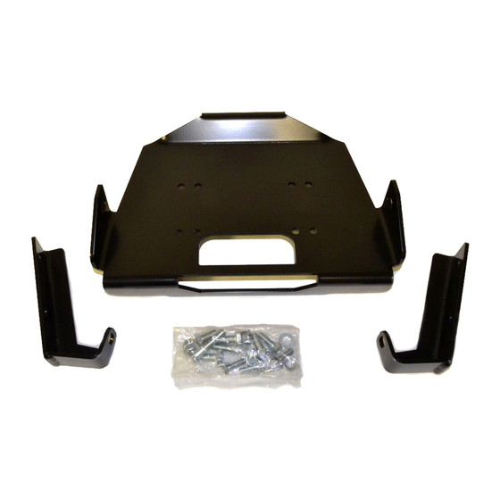
Page 13: Liste Des Pièces
V. LISTE DES PIÈCES Référence Qté Description 82139 Plaque de montage 80516 Support de montage de guide-câble gauche 80517 Support de montage de guide-câble droit 83069 Vis à tête hexagonale M10 x 1,25 x 45 mm 11524 Rondelle plate 3/8 73783 Écrou à tête hexagonale à épaulement M10 x 1,25 74514 Vis à... - Page 14 VI. INSTALLATION 1. Retirez, à l’aide d’une douille 14 mm, les vis à tête sur le côté du pare-chocs, tel qu’illustré à la figure 1. Le matériel de montage su- périeur sera utilisé pour réinstaller le pare- chocs. Retirer les vis à tête hexagonale Figure 1 2.
-
Page 15: Installation (Suite)
INSTALLATION (SUITE) 4. Retirez et conservez les deux attaches du milieu retenant la grille, tel qu’illustré à la figure 4. Figure 4 Retirer les attaches du milieu Figure 4 5. Retirez et conservez les deux attaches su- périeures retenant la grille, tel qu’illustré à la figure 5. - Page 16 INSTALLATION (SUITE) 7. Retirez les vis à tête du cadre du véhicule situées près du différentiel avant, à l’aide d’une douille 14 mm, tel qu’indiqué à la fig- ure 7. Ces vis à tête ne seront pas nécessaires pour l’installation de la plaque de montage. 8.
- Page 17 INSTALLATION (SUITE) 9. Installez la plaque de montage sur le véhi- cule, tel qu’indiqué à la figure 9. Glissez l’ensemble entre le tube du cadre et le dé- flecteur d’air du radiateur en position hori- zontale, treuil relevé. Une fois l’ensemble positionné...
- Page 18 INSTALLATION (SUITE) 12. Installez les vis à tête M10 x 1,25 x 45 mm sur la partie inférieure du pare-chocs, tel qu’illustré à la figure 12. Assurez-vous qu’elles passent par les fentes dans la plaque de montage du treuil, à l’intérieur des tubes du cadre du véhicule.
-
Page 19: L'installation De La Plaque De Montage Du Treuil Est À Présent Ter
INSTALLATION (SUITE) 15. Faites passer le câble de treuil par le guide- câble (fourni dans le kit de treuil) et fixez-le aux supports du guide-câble à l’aide de vis à tête M10 x 1,25 x 25 mm, de rondelles de blocage et d’écrous à épaulement. Serrez selon les couples de serrage appropriés. -
Page 20: Maintenance, Entretien
AVERTISSEMENT LE FAIT DE NE PAS SERRER SOLIDEMENT TOUS LES BOULONS DU TREUIL, DE LA PLAQUE DE TREUIL ET DU GUIDE-CÂBLE PEUT ENTRAÎNER UNE DÉFAILLANCE DU PRODUIT, CE QUI PEUT ENDOMMAGER LE VÉHICULE ET PROVOQUER DES BLESSURES OU LA MORT DE L’OPÉRATEUR. AVANT TOUTE UTILISATION, ASSUREZ-VOUS QUE TOUS LES BOULONS SONT BIEN SERRÉS. VI. MAINTENANCE/ENTRETIEN 1. Inspectez toutes les pièces du treuil, de la plaque de montage et le matériel de montage connexe avant toute utilisation. Remplacez tout matériel qui semble rouillé ou déformé. 2. Avant toute utilisation, inspectez tous les écrous et boulons du treuil, de la plaque de montage de lame et du matériel de montage connexe.