Chamberlain C610C Manuel Du Propriétaire
Ouvre-porte de garage à chaîne
Table des Matières
Les langues disponibles
Les langues disponibles
Liens rapides
Garage Opener
• Please read this manual and the enclosed safety materials carefully!
• Fasten the manual near the garage door after installation.
• The door WILL NOT CLOSE unless the Protector System
and properly aligned.
• Periodic checks of the garage door opener are required to ensure
safe operation.
• The model number label is located on the front panel of your garage
door opener.
• This garage door opener is compatible with MyQ® and
is connected
®
Security+ 2.0® accessories.
• DO NOT install on a one-piece door if using devices or features
providing unattended close. Unattended devices and features are
to be used ONLY with sectional doors.
Owner's Manual
C610C
Chain Drive
Garage Door Opener
FOR RESIDENTIAL USE ONLY
PRE-PROGRAMMED REMOTE CONTROL
INCLUDED
TO WATCH VIDEOS GO TO:
tinyurl.com/lgh5x3h
Contents
Preparation ......................................2-5
Assembly .......................................6-10
Installation .................................. 11-28
Install the Door Control ............ 21-22
Install the Protector System® .... 23-26
Connect Power ......................... 27-28
Adjustments ................................. 29-31
Operation ..................................... 32-36
Features .......................................33
Using your Garage Door Opener .....34
Motion Detecting Control Panel .....34
Keyless Entry ................................35
Homelink® ...................................36
To Erase the Memory .....................36
To Open the Door Manually ...........37
Maintenance .....................................38
Troubleshooting ........................... 39-40
Accessories ........................................41
Warranty ...........................................42
Repair Parts ................................. 43-44
www.chamberlain.com
www.mychamberlain.com
Chapitres
Table des Matières
Dépannage

Manuels Connexes pour Chamberlain C610C


Sommaire des Matières pour Chamberlain C610C
- Page 44 Manuel du propriétaire Matiéres C610C Préparation ........2-5 Ouvre-porte de garage Montage ........6-10 à chaîne Installation ........11-28 Pose de la commande de porte.. 21-22 Installation du dispositif POUR RÉSIDENCES SEULEMENT Protector System® ....23-26 Raccordement de TÉLÉCOMMANDE PRÉPROGRAMMÉE l’alimentation ......27-28 INCLUSE Réglages ........
-
Page 45: Préparation
Préparation Revue des symboles de sécurité et des mots de signalement Vérification de la porte Cet ouvre-porte de garage a été conçu et mis à l'essai dans le but d'offrir un service sûr à condition qu'il soit installé, utilisé, entretenu et mis à l'essai en stricte conformité avec les instructions et les avertissements contenus dans le présent manuel. -
Page 46: Articles Supplémentaires Dont Vous Pourriez Avoir Besoin
Préparation Articles supplémentaires dont vous pourriez avoir besoin : Outils nécessaires Examinez votre garage pour voir si vous avez besoin des articles suivants : (2) PLANCHES DE BOIS 2X4 Peuvent servir à fixer le support du linteau aux supports structuraux. Servent aussi à positionner l'ouvre- porte de garage pendant l'installation et à... -
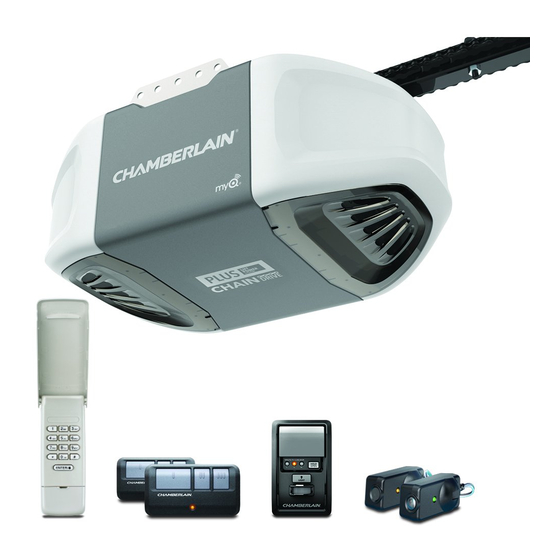
Page 47: Inventaire De La Boîte
Modèle Alimentation Commande de porte Télécommande Clavier sans fil ü C610C Plus Lift Power System™ Détection de mouvement 3 boutons (2) Support du linteau Poulie Support de porte Biellette courbée... - Page 48 Préparation Fixations LE MONTAGE LA POSE LA COMMANDE DE PORTE Écrou à oreilles Boulon Boulon Tire-fond de 1/4 de po-20 (2) 1/4 de po-20 x 1-3/4 de po 5/16 de po-9 x 1-5/8 de po (4) Vis autotaraudeuse Axe de chape de 5/16 de po x 1-1/2 de po 1/4 de po-14 x 5/8 de po (2) Chevilles pour murs secs (2)
-
Page 49: Montage
Montage 1re Montage du rail et pose du chariot Faire coulisser le rail jusqu’aux arrêts sur le Afin de prévenir une BLESSURE occasionnée par un pincement, tenir les mains et les doigts loin des joints lors de dessus et aux l'assemblage du rail. -
Page 50: Fixation Du Rail Au Moteur
Montage FIXATIONS 2e Fixation du rail au moteur Contre-écrou 1/4 de po-20 Boulon de 1/4 de po- Afin d'éviter d'endommager SÉRIEUSEMENT l'ouvre-porte de garage, utiliser UNIQUEMENT les boulons et les 20 x 1-3/4 de po fixations montés sur le dessus de l'ouvre-porte. Insérer un boulon 1/4 de po-20 x 1-3/4 de po, une rondelle du trou du boulon de protection du couvercle Boulons (Retirer depuis le dessus de l’ouvre-porte) -
Page 51: Installation De La Poulie
Montage 3e Installation de la poulie FIXATIONS Boulons Poser la chaîne/câble à côté du rail, comme illustré. Saisir l'extrémité avec la boucle du câble et passer environ 30 cm (12 po) de câble à travers la fenêtre. Laisser en suspension jusqu'à la 4e opération de montage. -
Page 52: Installation De La Chaîne
Montage 4e Installation de la chaîne FIXATIONS Maillon de raccord Tige filetée Pour éviter d'éventuelles BLESSURES GRAVES aux doigts par suite du mouvement de l'ouvre-porte : TOUJOURS garder la main à l'écart du pignon lorsque l'ouvre-porte fonctionne. Fixer solidement le carter du pignon AVANT de faire fonctionner l'ouvre-porte. Tirer le câble autour de la poulie et vers le chariot. -
Page 53: Tension De La Chaîne
Montage Écrou Rondelle Arbre du 5e Tension de la chaîne extérieur frein chariot Pour visser Dévisser l'écrou intérieur de la tige filetée du chariot et éloigner la rondelle. l'écrou extérieur Pour tendre la chaîne, tournez l'écrou extérieur dans le sens indiqué. Lorsque la chaîne est à... -
Page 54: Importantes Instructions Concernant L'installation
Installation IMPORTANTES INSTRUCTIONS CONCERNANT L'INSTALLATION Pour réduire le risque de BLESSURES GRAVES, voire MORTELLES : LIRE ET SUIVRE TOUS LES AVERTISSEMENTS ET INSTRUCTIONS DE POSE. Installer la commande de porte du garage murale : Poser l'ouvre-porte de garage UNIQUEMENT sur une porte de garage bien équilibrée et lubrifiée. Une porte bien en vue de la porte de garage;... -
Page 55: 1Re Déterminer L'emplacement Du Support De Linteau
Installation MONTAGE DU SUPPORT 1re Déterminer l’emplacement du support de linteau Linteau Ligne du centre vertical DE LINTEAU AU PLANFOND de la porte de garage EN OPTION Solives Plafond Pour éviter des BLESSURES GRAVES, VOIRE MORTELLES : non fini Le support de linteau DOIT être fixé DE MANIÈRE RIGIDE à la solive sur le linteau ou le plafond, sinon la porte de garage pourrait ne PAS remonter, au besoin. -
Page 56: Pose Du Support De Linteau
Installation INSTALLATION AU MUR 2e Pose du support de linteau Linteau Ligne du centre Le support de linteau peut être fixé soit sur le mur, au-dessus de la porte, soit sur le plafond. Suivre les instructions vertical de la 2 x 4 fixé sur qui répondent le mieux aux besoins particuliers. -
Page 57: Fixation Du Rail Sur Le Support De Linteau
Installation 3e Fixation du rail sur le support de linteau 4e Positionnement de l'ouvre-porte de garage Positionner l'ouvre-porte de garage sur le plancher, juste sous le support de linteau. Utiliser une des boîtes d'emballage pour le protéger. REMARQUE : Si le ressort de la porte gêne, il faudra demander de l’aide. Demander à une personne de bien retenir l'ouvre-porte sur un support temporaire de façon que le rail ne touche pas le ressort. -
Page 58: Accrochage De L'ouvre-Porte De Garage
Installation 5e Accrochage de l’ouvre-porte de garage FIXATIONS Écrou de Tire-fond de 5/16 de po-18 5/16 de po- 9 x 1-5/8 de po Pour éviter d'éventuelles BLESSURES GRAVES par suite de la chute d'un ouvre-porte de garage, fixer l'ouvre- porte SOLIDEMENT aux solives du garage. Des ancrages en béton DOIVENT être utilisés lors de l'installation Boulon hexagonal de Rondelle-frein des supports dans la maçonnerie. -
Page 59: Fixation Des Ampoules
Installation 6e Fixation des ampoules 7e Pose de la corde et de la poignée de déclenchement d'urgence Pour éviter toute SURCHAUFFE éventuelle du panneau d'extrémité ou de la douille d'éclairage : Pour prévenir d'éventuelles BLESSURES GRAVES ou LA MORT par suite de la chute d'une porte de garage : Utiliser UNIQUEMENT une ampoule à... - Page 60 Installation 8e Pose du support de porte FIXATIONS Vis autotaraudeuse 1/4 de po-14 x 5/8 de po Les portes de garage en fibre de verre, en aluminium ou en acier léger DOIVENT être renforcées AVANT la fixation du support de porte. Contacter le fabricant de la porte de garage ou lâ installateur pour les instructions relatives aux renforts ou obtenir un nécessaire de renforts.
- Page 61 Installation Linteau 8e Pose du support de porte (suite) (Plafond fini) Support 2 x 4 OPTION B PORTE RIGIDES Support de linteau Centrer le support de porte sur le dessus de la porte, en l'alignant avec le support de linteau, comme il est illustré.
-
Page 62: Fixation De La Biellette De La Porte Au Chariot
Installation FIXATIONS 9e Fixation de la biellette de la porte au chariot Les méthodes de pose varient en fonction de la porte du garage. Suivre les instructions qui correspondent à la porte du garage sur laquelle on pose l'ouvre-porte. OPTION A PORTES ARTICULÉES Axe de chape de 5/16 de po x Axe de chape de... -
Page 63: Fixation De La Biellette De La Porte Au Chariot (Suite)
Installation 9e Fixation de la biellette de la porte au chariot (suite) OPTION B PORTE RIGIDES Biellette droite IMPORTANT : la rainure de la biellette de porte droite DOIT pointer loin de la biellette de porte courbée. (Rainure faisant facea l’oppose) Fermer la porte. -
Page 64: 10E Pose De La Commande De Porte
Compatible avec les accessoires MyQ , voir page 41. Votre porte de garage est compatible avec un maximum de ® 2 accessoires MyQ . REMARQUE : Les anciennes commandes de porte Chamberlain et les produits de tiers ne BOÎTE SIMPLE MUR SEC sont pas compatibles. -
Page 65: Raccordement Des Fils De La Commande De Porte À L'ouvre-Porte De Garage
Installation 11e Raccordement des fils de la commande de porte à l'ouvre-porte 12e Fixation des étiquettes d'avertissement de garage Fixer l'étiquette d'avertissement sur le mur, près de la commande de porte, avec des punaises ou des agrafes. Acheminer les fils blanc et rouge/blanc de la commande de porte vers l’ouvre-porte de garage. Fixer le fil Placer l'étiquette concernant l'essai d'inversion de sécurité/ouverture manuelle bien en vue sur le côté... -
Page 66: 13E Installation Du Dispositif Protector System
Installation ® FIXATIONS 13e Installation du dispositif Protector System Boulon à tête bombée Écrou à oreilles et collet carré de 1/4 de po-20 1/4 de po-20 x 1/2 de po S'assurer que l'ouvre-porte de garage est hors tension AVANT de poser le capteur d'inversion de sécurité. Pour prévenir des BLESSURES GRAVES ou LA MORT par suite d'une porte de garage qui se ferme : Les capteurs d'inversion de sécurité... - Page 67 Installation ® OPTION C POSE AU SOL 13e Installation du dispositif Protector System (suite) Utiliser un support de rallonge (non fourni) ou un bloc de bois pour soulever le support de capteur, au besoin. OPTION B POSE MURALE Mesurer soigneusement la position des deux supports de capteurs de sorte qu'ils seront à la même distance du mur et dégagés.
-
Page 68: Câblage Des Capteurs D'inversion De Sécurité
Installation 14e Câblage des capteurs d'inversion de sécurité FIXATIONS Agrafes isolées (Non illustrés) Si votre porte de garage est déjà câblée pour l'installation de capteurs d'inversion de sécurité, passer à la page 26. OPTION A INSTALLATION SANS CÂBLES PRÉINSTALLÉS Faire acheminer le câble des deux capteurs vers l'ouvre-porte de garage. Fixer le câble au mur et au Agrafe plafond avec les agrafes. -
Page 69: Câblage Des Capteurs D'inversion De Sécurité (Suite)
Installation 14e Câblage des capteurs d'inversion de sécurité (suite) Câbles 11 mm préinstallés (7/16 de po) Câbles du capteur OPTION B de l’inverseur de INSTALLATION PRÉCÂBLÉE sécurité Couper l'extrémité du câble du capteur d'inversion de sécurité en s'assurant qu''il reste suffisamment de longueur pour atteindre les câbles préinstallés du mur. -
Page 70: 15E Raccordement De L'alimentation
Installation IL Y A DEUX OPTIONS CONCERNANT LA PRISE D'ALIMENTATION : 15e Raccordement de l'alimentation OPTION A CÂBLAGE TYPIQUE Brancher l’ouvre-porte de garage dans une prise mise à la terre. NE PAS faire fonctionner l'ouvre-porte de garage pour le moment. Pour éviter toute BLESSURE potentielle GRAVE voire MORTELLE par électrocution ou brûlure : OPTION B CÂBLAGE PERMANENT... -
Page 71: Montage Des Détecteurs Inverseurs Du Securitié
Installation SI LE TÉMOIN DEL AMBRE DU DÉTECTEUR ÉMETTEUR NE S'ALLUME PAS : 16e Montage des détecteurs inverseurs du securitié S’assurer que l’ouvre-porte de garage reçoit bien l’alimentation électrique. La porte ne se fermera pas si les détecteurs n'ont pas été installés et alignés correctement. S’assurer que le fil du détecteur n’est pas court-circuité... -
Page 72: Réglages
Réglages Portes rigides uniquement Introduction Lors du réglage de la course vers le haut d'une porte rigide, s'assurer que la porte ne penche pas vers l'arrière lorsqu'elle est complètement ouverte. Si la porte est penchée vers l'arrière, cela causera un mouvement brusque de la porte lors de l'ouverture ou de la fermeture. -
Page 73: 1Re Programmation De La Course
Réglages 1re Programmation de la course Bouton « UP » Bouton de réglage Sans un système d'inversion de sécurité bien installé, des personnes (plus particulièrement les petits enfants) pourraient être GRIÈVEMENT BLESSÉES ou TUÉES par une porte de garage qui se referme. Bouton «... -
Page 74: Essai Du Système D'inversion De Sécurité
Réglages ® 2e Essai du système d'inversion de sécurité 3e Essai du Protector System Sans un système d'inversion de sécurité bien installé, des personnes (plus particulièrement les petits enfants) Sans un système d'inversion de sécurité bien installé, des personnes (plus particulièrement les petits enfants) pourraient être GRIÈVEMENT BLESSÉES ou TUÉES par une porte de garage qui se referme. -
Page 75: Fonctionnement
Fonctionnement IMPORTANTES CONSIGNES DE SÉCURITÉ Pour réduire le risque de BLESSURES GRAVES, voire MORTELLES : LIRE ET RESPECTER TOUS LES AVERTISSEMENTS ET TOUTES LES INSTRUCTIONS. Après avoir effectué QUELQUE réglage que ce soit, on DOIT faire l'essai du système d'inversion de Garder EN TOUT TEMPS la télécommande hors de portée des enfants. -
Page 76: Caractéristiques
MyQ , voir la page 41. supplémentaire des ampoules de votre ouvre-porte de garage, reportez-vous au page 34. REMARQUE : Les anciens telecommandes, commandes de porte Chamberlain, et les produits de tiers ne son pas compatibles. ® Accessoires MyQ CAPACITÉ... -
Page 77: Utilisation De Votre Ouvre-Porte De Garage
Fonctionnement Utilisation de votre ouvre-porte de garage FONCTIONS DE LA PANNEAU DE COMMANDE AVEC DÉTECTION DE MOUVEMENT BARRE DE POUSSÉE L’ouvre-porte de garage peut être activé par une commande de porte murale, une télécommande, un émetteur à code ® ou un accessoire MyQ Appuyer sur la touche-poussoir pour ouvrir ou fermer la porte. -
Page 78: Télécommandes Et Émetteurs À Code
à partir de la commande de porte et de télédéverrouillage.Cette fonction Chamberlain plus anciennes ne sont PAS compatibles, consulter la page 41 pour les accessoires compatibles. est utile pour avoir l'esprit en paix lorsque la maison est vide (p. ex.,pendant les vacances).Cette fonction est utile PROGRAMMATION AVEC LA COMMANDE DE PORTE pour avoir l'esprit en paix lorsque la maison est vide (p. -
Page 79: Homelink
Pour regarder une vidéo, aller à tinyurl.com/lcsf6xt ® HomeLink ® Si votre véhicule est équipé de HomeLink , il sera peut être nécessaire de se procurer un pont Compatability Bridge™ (non inclus) pour certains véhicules. Aller à bridge.chamberlain.com pour savoir si un pont sera nécessaire. -
Page 80: Ouverture Manuelle De La Porte
Fonctionnement Ouverture manuelle de la porte Pour prévenir d'éventuelles BLESSURES GRAVES ou LA MORT par suite de la chute d'une porte de garage : Si possible, utilisez la poignée de déclenchement d'urgence pour dégager le chariot UNIQUEMENT lorsque la porte de garage est FERMÉE. Des ressorts faibles ou brisés ou une porte déséquilibrée peuvent provoquer la chute rapide et/ou imprévue d'une porte ouverte. -
Page 81: Entretien
Entretien Calendrier d’entretien AVIS : Cet appareil est conforme aux dispositions de la partie 15 du règlement de la FCC et de l’exemption de licence IC (Industrie Canada) RSS. L’utilisation est assujettie aux deux conditions suivantes : (1) ce dispositif ne peut causer d’interférences nuisibles, et (2) ce dispositif doit accepter toute interférence reçue, y compris toute CHAQUE MOIS interférence pouvant causer un fonctionnement non désiré. -
Page 82: Dépannage
Dépannage Fiche diagnostique Des fonctions d'autodiagnostic ont été programmées dans votre ouvre-porte de garage. Les flèches vers le haut et le bas de l'ouvre-porte de garage font clignoter les codes d'anomalie. CODE D'ANOMALIE SYMPTÔME SOLUTION La flèche vers La flèche vers le le haut clignote bas clignote L'ouvre-porte de garage ne ferme pas la porte et l'éclairage clignote. - Page 83 Un pont Compatability Bridge™ (non inclus) sera peut-être nécessaire pour certains véhicules. Aller à Ma porte ne se ferme pas et les ampoules de l'éclairage du moteur clignotent : bridge.chamberlain.com pour savoir si un pont sera nécessaire. Le capteur d'inversion de sécurité doit être connecté et aligné correctement avant que l'ouvre-porte de garage n'entame le mouvement de fermeture.
-
Page 84: Accessoires
à l’aide d’un NIP à quatre Compatible avec MyQ ® chiffres. Fonctionne avec TOUS Comprend l’agrafe de paresoleil. les ouvre-porte Chamberlain fabriqués depuis 1993. ® Compatible avec MyQ CLLP1 Dispositif laser d’assistance 956EVC Télécommande porte-clés :...