Harvia Griffin CG170-U1 Instructions D'installation Et D'utilisation
Masquer les pouces
Voir aussi pour Griffin CG170-U1:
- Manuel de l'utilisateur/opérateur (24 pages) ,
- Manuel de l'utilisateur (20 pages) ,
- Manuel de l'utilisateur/opérateur (20 pages)

Manuels Connexes pour Harvia Griffin CG170-U1


Sommaire des Matières pour Harvia Griffin CG170-U1
- Page 1 HArvIA GrIffIn Instructions for Installation and Use of Control Unit Instructions d'installation et d'utilisation du centre de contrôle 14012010...
-
Page 2: Table Des Matières
à la personne chargée de maintaining them. Congratulations on making an leur maintenance. félicitations pour cet excellent excellent choice and choosing a Harvia control choix ! unit! HArvIA GrIffIn COnTrOL UnIT (CG170-U1��... -
Page 3: Harvia Griffin
1. HArvIA GrIffIn 1.1. General 1.1. Généralités The Harvia Griffin control unit can be used to Le centre de contrôle Harvia Griffin sert à contrôler control sauna heaters within an output range of un poêle électrique avec une puissance de sortie de 2.3–15 kW. -
Page 4: Troubleshooting
1.3. Troubleshooting 1.3. dépannage If an error occurs, the power to the heater will be Si une erreur se produit, la poêle sera mis hors ten- cut off and the control panel will show an error sion et le tableau de commande affichera un mes- sage d’erreur «... -
Page 5: Instructions For Use
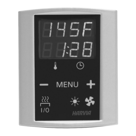
2. InsTrUCTIOns fOr Use 2. mOde d’empLOI 2.1. Using the Heater 2.1. Utiliser la poêle WArnInG! before s�itching the heater on al�ays remArQUe ! Avant la mise en marche de la poêle�� véri- check that there isn’t anything on top of the heater fier qu’aucun objet n’est posé... - Page 6 basic mode (heater on) mode basique (poêle allumé) The top row shows the temperature in the La ligne supérieure montre la température du sauna room. The bottom row shows the sauna. La ligne inférieure montre la durée de remaining on time. Both indicator lights glow. fonctionnement restante.
- Page 7 maximum on-time 1–18 h durée de fonctionnement maximale 1–18 heures (fOr COmmerCIAL Use OnLY) (À L’UsAGe COmmerCIAL seULemenT) 1. Switch the power off from the main switch. 1. Eteignez l’alimentation depuis le commutateur 2. Press and hold the buttons principal. 2.
-
Page 8: Instructions For Installation
3. InsTrUCTIOns fOr InsTALLATIOn 3. InsTrUCTIOns d’InsTALLATIOn The electrical connections of the control unit Les connexions électriques du centre de contrôle may only be made by an authorised�� professional peuvent uniquement être effectuées par un élec- electrician and in accordance �ith the current tricien professionnel agréé... - Page 9 mOdeL WATTs Amps vOLTAGe pH WIre sIZe/CALIbre de fIL AmpÈres TensIOn mOdÈLe breaker to po�er unit po�er unit to heater du coupe-circuit au bloc d’alimentation du bloc d’alimentation au poêle KIP-30-W1, FIN-30 3 000 12,5 #14 copper/cuivre (2) #14 copper/cuivre KIP-45-W1, FIN-45 4 500 18,8 #12 copper/cuivre...
- Page 10 mOdeL WATTs Amps vOLTAGe pH WIre sIZe/CALIbre de fIL AmpÈres TensIOn mOdÈLe breaker to po�er unit po�er unit to heater du coupe-circuit au bloc du bloc d’alimentation au d’alimentation poêle KIP-30-W3, FIN-30-W3 3 000 #16 copper/cuivre #16 copper/cuivre KIP-45-W3, FIN-45-W3 4 500 12,5 #14 copper/cuivre #14 copper/cuivre...
-
Page 11: Electrical Connections
3.2.1. electrical Connections 3.2.1. raccordement électrique Figures 6a and 6b show the electrical connections Les figures 6a et 6b montre les connexions élec- of the power unit. Tables 2 and 3 show the wire and triques du bloc d’alimentation. Les tableaux 2 et fuse sizes. - Page 12 CG170-U1/ CG170-U1L/ CG170-U1L/ CG170-U1L/ CG170-U1L/ CG170-U1L/ CG170-U1L/ CG170-U1L/ CG170-U3 CG170-U3L CG170-U3L CG170-U3L CG170-U3L CG170-U3L CG170-U3L CG170-U3L WX312 Sauna WX232 WIRE LOOP WIRE LOOP WX312 WX312 WX232 Figure 7. Multidrive Figure 7. Multidrive min. 3 15/16” (100 mm) Sensor max. Capteur Sensor 7 7/8”...
-
Page 13: Resetting The Overheat Protector
Sensor Capteur 5 7/8“ (150 mm) mOdeL/mOdÈLe KIP-30-W1, FIN-30, KIP-45-W1, FIN-45 KIP-60-W1, FIN-60, KIP-80-W1, FIN-80 KIP-30-W3, FIN-30-W3, KIP-45-W3, FIN-45-W3 KIP-60-W3, FIN-60-W3, KIP-80-W3, FIN-80-W3 Figure 9. The place of the temperature sensor of Figure 10. Sensor’s minimum distance from an air vent the control unit in connection �ith �all- Figure 10. -
Page 14: Spare Parts
4. spAre pArTs 4. pIÈCes de reCHAnGe 1 Control panel (CG170-U1, CG170-U3) Tableau de commande (CG170-U1, CG170-U3) WX360 2 Data cable Câble de commandes 5 m WX311 3 Data cable extension (optional) Câble de rallonge 10 m (en option) WX313 4 Temperature sensor Capteur de température WX232... -
Page 15: Guarantee
à l’importateur dans les 15 jours suivant l’achat. La garantie s’applique uniquement à la première instal- lation du produit et à l’acheteur d’origine. Harvia control unit model/modèle de centre de contrôle Harvia model number/numéro de modèle date of purchase/date d’achat Original purchaser/Acheteur d’origine...