Publicité

Les langues disponibles
  • FR

Les langues disponibles

  • FRANÇAIS, page 1

Liens rapides

Daker DK 4.5, 6, 10 kVA
®
Manuel d'installation • Installation manual
Part. LE05380AC-07/13-01 GF

Publicité

Table des Matières
loading

Sommaire des Matières pour LEGRAND Daker DK 4.5 kVA

  • Page 1 Daker DK 4.5, 6, 10 kVA ® Manuel d’installation • Installation manual Part. LE05380AC-07/13-01 GF...
  • Page 2 ® Daker DK 4.5, 6, 10 kVA frAnçAis english iTAliAnO DeUTsCh esPAÑOl...
  • Page 3: Table Des Matières

    Daker DK 4.5, 6, 10 kVA indice 1 introduction 2 Conditions d’utilisation 3 Panneau lCD 4 Panneau arrière 5 installation 6 logiciel d’autodiagnostic ups communicator 7 Dysfonctionnements possibles 8 Caractéristiques techniques...
  • Page 4: Introduction

    ® 1 introduction Ce manuel contient les informations concernant l’utilisation des modèles Daker DK 4.5, 6, 10 kVA. Il est recommandé de lire attentivement ce manuel avant de procéder à l’installation de l’onduleur et de respecter scrupuleusement les instructions ci-dessous. Les UPS Daker DK 4.5, 6, 10 kVA sont conçus pour une utilisation domestique ou industrielle.
  • Page 5: Panneau Lcd

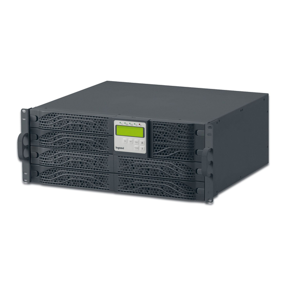
    Daker DK 4.5, 6, 10 kVA 3 Panneau lCD Panneau LCD Le LED vert allumé indique que l’UPS peut fonctionner en redondance. Le LED vert allumé indique que l’alimentation sur secteur est comprise entre 160 et 288 Vca. Le LED vert clignotant indique que l’alimentation sur secteur est hors des limites acceptables. Le LED vert allumé...
  • Page 6 ® 3 Panneau lCD Er05 symboles écran lCD Er06 réf. symbole Description réf. symbole Description Courant excessif LINE Er10 Alimentation sur secteur variateur fréquence Er11 Niveau batterie fiable Surchauffe Er12 Batterie endommagée Surcharge en sortie Er14 Surcharge Ventilateurs défectueux Fonctionnement en Erreur procédure Er15 Service Mode...
  • Page 7: Panneau Arrière

    Daker DK 4.5, 6, 10 kVA 4 Panneau arrière RS232 OUTPUT INPUT 3 100 56 Ext. Battery 3 100 57 Utility Input Breaker 17-18 17-18 3 100 53 3 100 54 UTILITY INPUT BREAKER BYPASS 3 100 58 INPUT CH B BREAKER SLOT 3 100 59...
  • Page 8: Réglages Interface

    ® 4 Panneau arrière réglages interface 3 100 53/54/55/56/57 OUTPUT INPUT N22 L21 L21-N22: UPS OUTPUT L12-N1: UTILITY INPUT OUTPUT EARTH INPUT EARTH GROUND GROUND 3 100 58 3 100 59 OUTPUT OUTPUT UTILITY BYPASS INPUT INPUT DIM ONLY l11-n1 : bornes non utilisées sur cette version l12-n1 : bornes de branchement au réseau d’entrée UPS (3 100 58) r-s-T-n1 : bornes de branchement au réseau d’entrée UPS (3 100 59) g1 :...
  • Page 9: Installation

    Daker DK 4.5, 6, 10 kVA 5 installation Contrôler le contenu de l’emballage : • Mode d’emploi • Câble de communication RS232 • Accessoires de configuration Tower/rack 3 100 53/54/56/57 3 100 58/59 x2 2U x2 3U x2 4U ±1.0mm ±1.0mm ±1.0mm 3 100 53/54/56/57 x8...
  • Page 10 ® 5 installation Configuration tower step 1 step 2 Optional...
  • Page 11 Daker DK 4.5, 6, 10 kVA UPs + armoire batterie step 1 step 2...
  • Page 12 ® 5 installation Configuration rack 19” step 1 step 2 step 3 90° step 4...
  • Page 13 Daker DK 4.5, 6, 10 kVA step 5 step 6...
  • Page 14 ® 5 installation Au dos de l'UPS sont prévus les branchements suivants : • Prises de sortie et connecteur d’entrée [17] ou [18] : à ces deux connecteurs, brancher le câble d’alimentation et les câbles de sortie fournis à cet effet. •...
  • Page 15 Daker DK 4.5, 6, 10 kVA AVerTisseMenT Pour des raisons de sécurité, il est recommandé de ne pas modifier les câbles fournis ; en outre, il est nécessaire de s’assurer que le prise de secteur à laquelle le groupe de continuité est branché...
  • Page 16: Données Par Défaut Et Fonctions Spéciales

    ® 5 installation Données par défaut et fonctions spéciales A l’issue du bon allumage de l’UPS, appuyer sur le bouton Fonctions spéciales pour passer à l’option montrée sur la figure Q1. avertisseur sonore “On” avertisseur sonore “Off” Appuyer sur la touche pour modifier les réglages de l’UPS.
  • Page 17 Daker DK 4.5, 6, 10 kVA Tension de sortie variateur UPS en fonctionnement Normal UPS en fonctionnement “Ecomode” UPS fonctionnant en “CVCF 50 Hz mode”. UPS fonctionnant en “CVCF 60 Hz mode”. Ajustement Tension de sortie (-3% à 3%) Fonctionnement en parallèle activé...
  • Page 18 ® 5 installation Appuyer sur la touche “Haut” pour régler les fonctions spéciales. Les fonctions incluent Avertisseur sonore ON (figure Q1), Avertisseur sonore OFF (figure Q2, alarme désactivée en cas de signaux provenant de l’UPS) et Self-test ON (figure r1) ou ON (figure r2). L’UPS effectue ensuite le test des batteries pendant 10 secondes).
  • Page 19: Connexion

    Daker DK 4.5, 6, 10 kVA Une fois les paramètres voulus réglés, il est nécessaire d’appuyer sur la touche “Enter” , quand l’écran affiche la figure Z, pour sauvegarder toutes les modifications. Ensuite, l’UPS affiche la figure AA pour indiquer que les réglages ont été appliqués. Pour annuler les réglages effectués, maintenir enfoncée la touche “OFF”...
  • Page 20: Logiciel D'autodiagnostic Ups Communicator

    ® 6 logiciel d’autodiagnostic ups communicator Sur le site www.ups.legrand.com, il est possible de télécharger gratuitement un logiciel d’autodia- gnostic pour WINDOWS (16 et 32 bits) et Linux. Ce logiciel fournit les fonctions suivantes : - Visualisation de toutes les données de fonctionnement et de diagnostic en cas de problème.
  • Page 21: Caractéristiques Techniques

    Daker DK 4.5, 6, 10 kVA 8 Caractéristiques techniques sPéCifiCATiOns De COnsTrUCTiOn 3 100 53 3 100 54 Poids 52 Kg 52 Kg Dimensions L x H x P en millimètres 440 x 176 x 680 440 x 176 x 680 Contre les surcharges et les courts-circuits Blocage du fonctionnement dû...
  • Page 22 ® 8 Caractéristiques techniques sPéCifiCATiOns De COnsTrUCTiOn 3 100 53 3 100 54 Caractéristiques électriques de sortie avec alimentation Tension nominale de sortie 230 V ± 2% Fréquence de sortie 50/60 Hz ± 0.5% Puissance active de sortie 4,05kW 5,4kW sur charge non linéaire Puissance apparente de sortie 4,5kVA...
  • Page 23 Daker DK 4.5, 6, 10 kVA sPéCifiCATiOns 3 100 56 3 100 57 3 100 58 3 100 59 De COnsTrUCTiOn Poids 25 Kg 25 Kg 26 Kg Dimensions L x H x P en millimètres 440 x 88 x 680 440 x 88 x 680 440 x 132 x 680 Contre les surcharges et les courts-circuits Blocage du fonctionnement dû...
  • Page 24: Spécifications

    ® 8 Caractéristiques techniques sPéCifiCATiOns 3 100 56 3 100 57 3 100 58 3 100 59 De COnsTrUCTiOn Caractéristiques électriques de sortie avec alimentation Tension nominale de sortie 230 V ± 2% Fréquence de sortie 50/60 Hz ± 0.5% Puissance active de sortie 4.05kW 5.4kW...
  • Page 25 Daker DK 4.5, 6, 10 kVA index 1 introduction 2 Conditions of use 3 lCD Panel 4 rear panel 5 installation 6 UPs communicator self-diagnostic software 7 Possible malfunctioning 8 Technical features...
  • Page 26: Introduction

    ® 1 introduction This manual contains information for users of the Daker DK 4.5, 6, 10 kVA models. You are advised to read this handbook carefully before installing your uninterruptible power sup- ply, meticulously following the instructions given herein. The UPS Daker DK is only been made for civil or industrial use; it is not in conformity with the stan- dards for electro-medical equipment.
  • Page 27: Lcd Panel

    Daker DK 4.5, 6, 10 kVA 3 lCD Panel LCD panel Green LED indicates that the UPS is able to run under redundancy mode. Solid green LED indicates that the utility input voltage is within the window. Flashing green LED indicates that the utility input voltage is within the acceptable window. Green LED indicates that Bypass Input is normal.
  • Page 28 ® 3 lCD Panel Er05 Display lCD symbols Er06 item symbol Description item symbol Description LINE Er10 Utility or Bypass Source Inverter Over-current Er11 Battery Low The UPS is overheated Er12 Battery Abnormal UPS Output Overloading Er14 UPS Overloading Fan Error UPS Working Wrong Procedure to Er15...
  • Page 29: Rear Panel

    Daker DK 4.5, 6, 10 kVA 4 rear panel RS232 OUTPUT INPUT 3 100 56 Ext. Battery 3 100 57 Utility Input Breaker 17-18 17-18 3 100 53 3 100 54 UTILITY INPUT BREAKER BYPASS 3 100 58 INPUT CH B BREAKER SLOT 3 100 59...
  • Page 30: Interface Settings

    ® 4 rear panel interface settings 3 100 53/54/55/56/57 OUTPUT INPUT N22 L21 L21-N22: UPS OUTPUT L12-N1: UTILITY INPUT OUTPUT EARTH INPUT EARTH GROUND GROUND 3 100 58 3 100 59 OUTPUT OUTPUT UTILITY BYPASS INPUT INPUT DIM ONLY l11-n1 : clamps not used in this version l12-n1 : clamps for connection to the UPS input line (3 100 58) r-s-T-n1 : clamps for connection to the UPS input line (3 100 59) clamp for UPS input ground cable connection...
  • Page 31: Installation

    Daker DK 4.5, 6, 10 kVA 5 installation Check for the following standard package contents: • User Manual • RS-232 communication cable • Tower/Rack Accessories Kit as below: 3 100 53/54/56/57 3 100 58/59 x2 2U x2 3U x2 4U ±1.0mm ±1.0mm ±1.0mm...
  • Page 32 ® 5 installation Tower configuration setup step 1 step 2 Optional...
  • Page 33 Daker DK 4.5, 6, 10 kVA UPs + battery cabinet step 1 step 2...
  • Page 34 ® 5 installation Configuration rack 19” step 1 step 2 step 3 90° step 4...
  • Page 35 Daker DK 4.5, 6, 10 kVA step 5 step 6...
  • Page 36 ® 5 installation On the rear of the uninterruptible power supply are the following connections: • Output sockets and input connector (17) or (18): connect to these connectors the power cable and the output cables included. • Socket for connecting computer serial interface RS232 (9 female pins) [4]: required when using the diagnostic and shutdown management software.
  • Page 37 Daker DK 4.5, 6, 10 kVA WArning For safety reasons it is advised not to modify the cables supplied; it is also necessary to make sure that the mains socket the uninterruptible power supply is connected to is fitted with a safe connection to the earth system, and appropriate protection in accordance with current regulations.
  • Page 38 ® 5 installation Default data and special function execution After the UPS completely starts up, press the key to change the LCD display to figure Q1. buzzer “On” buzzer “Off” Press the key to scroll through the UPS settings. The LCD will display in sequence figure Q1 (buzzer) figure r1 (Self-test) figure s1 (Bypass figure T (Output Frequency Synchronization Window)
  • Page 39 Daker DK 4.5, 6, 10 kVA inverter output voltage The UPS is operating in “normal mode” The UPS is operating in “Eco mode” The UPS is operating in “CVCF 50 Hz mode” The UPS is operating in “CVCF 60 Hz mode” Output Voltage Adjustment (-3% to 3%) UPS position in parallel mode...
  • Page 40 ® 5 installation Press the scroll up key to execute special functions. The functions include buzzer ON (as in figure Q1), buzzer OFF (as in figure Q2, Alarm silence for UPS Warning), and self-test OFF (as in figure r1) or self-test ON (as in figure r2). The UPS will execute the battery test for ten seconds.
  • Page 41 Daker DK 4.5, 6, 10 kVA After changing settings you must scroll to the “save” screen (figure Z) and then press the enter key to save all of your changes. Then the LCD will display figure AA to indicate completion of the setting changes.
  • Page 42: Ups Communicator Self-Diagnostic Software

    ® 6 UPs communicator self-diagnostic software From the website www.ups.legrand.com it is possible to download free of charge a self-diagnostic software running on WINDOWS (16 e 32 bit) e Linux platforms. This software can be used for the following functions: - Display of all the operation and diagnostic data in case of problems.
  • Page 43: Technical Features

    Daker DK 4.5, 6, 10 kVA 8 Technical features COnsTrUCTiOn sPeCifiCATiOns 3 100 53 3 100 54 Weights 52 Kg 52 Kg Dimensions L x H x P in mm 440 x 176 x 680 440 x 176 x 680 Electronic protection against overloading and short-circuiting.
  • Page 44: Construction Specifications

    ® 8 Technical features COnsTrUCTiOn sPeCifiCATiOns 3 100 53 3 100 54 electrical specifications on output with battery operation Rated output voltage 230 V ± 2% Output frequency 50/60 Hz ± 0.5% Active output capacity on non-linear load 4.05kW 5.4kW Apparent output capacity on non-linear load 4.5kVA 6kVA...
  • Page 45 Daker DK 4.5, 6, 10 kVA COnsTrUCTiOn 3 100 56 3 100 57 3 100 58 3 100 59 sPeCifiCATiOns Weights 25 Kg 25 Kg 26 Kg Dimensions L x H x P in mm 440 x 88 x 680 440 x 88 x 680 440 x 132 x 680 Electronic protection against overloading and short-circuiting.
  • Page 46 ® 8 Technical features COnsTrUCTiOn 3 100 56 3 100 57 3 100 58 3 100 59 sPeCifiCATiOns electrical specifications on output with battery operation Rated output voltage 230 V ± 2% Output frequency 50/60 Hz ± 0.5% Active output capacity 4.05kW 5.4kW on non-linear load...
  • Page 47 Daker DK 4.5, 6, 10 kVA indice 1 introduzione 2 Condizioni d’uso 3 Pannello lCD 4 Pannello posteriore 5 installazione 6 software autodiagnostico Ups communicator 7 Possibili malfunzionamenti 8 Caratteristiche tecniche...
  • Page 48: Introduzione

    ® 1 introduzione Questo manuale contiene le informazioni per l’utente relative ai modelli Daker DK 4.5, 6, 10 kVA. Si consiglia di leggere attentamente questo manuale prima di procedere all’installazione del grup- po di continuità, attenendosi scrupolosamente a quanto di seguito riportato. Gli UPS Daker DK 4.5, 6, 10 kVA sono realizzati per uso civile o industriale;...
  • Page 49: Pannello Lcd

    Daker DK 4.5, 6, 10 kVA 3 Pannello lCD Pannello LCD LED verde acceso indica che l’UPS può funzionare in ridondanza. LED verde acceso fisso indica che la rete di alimentazione è all’interno del range 160-288 VAC. LED verde lampeggiante indica che la rete di alimentazione è fuori dal range accettabile. LED verde acceso indica che la rete di Bypass è...
  • Page 50 ® 3 Pannello lCD Er05 simboli lCD Display Er06 item symbol Description item symbol Description Corrente eccessiva LINE Er10 Sorgente di linea Inverter Er11 Livello batteria basso Sovratemperatura Er12 Batteria danneggiata Sovraccarico in uscita Er14 Sovraccarico Ventole difettose Funzionamento Errore procedura Er15 in Service Mode “Modo Manutenzione”...
  • Page 51: Pannello Posteriore

    Daker DK 4.5, 6, 10 kVA 4 Pannello posteriore RS232 OUTPUT INPUT 3 100 56 Ext. Battery 3 100 57 Utility Input Breaker 17-18 17-18 3 100 53 3 100 54 UTILITY INPUT BREAKER BYPASS 3 100 58 INPUT CH B BREAKER SLOT 3 100 59...
  • Page 52 ® 4 Pannello posteriore interface settings 3 100 53/54/55/56/57 OUTPUT INPUT N22 L21 L21-N22: UPS OUTPUT L12-N1: UTILITY INPUT OUTPUT EARTH INPUT EARTH GROUND GROUND 3 100 58 3 100 59 OUTPUT OUTPUT UTILITY BYPASS INPUT INPUT DIM ONLY l11-n1: terminali non utilizzati in questa versione l12-n1: terminali per il collegamento alla rete di ingresso UPS(3 100 58) r-s-T-n1 : terminali per il collegamento alla rete di ingresso UPS (3 100 59) terminale per collegamento cavo di terra ingresso UPS...
  • Page 53: Installazione

    Daker DK 4.5, 6, 10 kVA 5 installazione Verificare il corretto contenuto dell’imballo: • Manuale d’uso • Cavo di comunicazione RS232 • Accessori per configurazione Tower/rack 3 100 53/54/56/57 3 100 58/59 x2 2U x2 3U x2 4U ±1.0mm ±1.0mm ±1.0mm 3 100 53/54/56/57 x8 3 100 58 x7...
  • Page 54 ® 5 installazione Configurazione Tower step 1 step 2 Optional...
  • Page 55 Daker DK 4.5, 6, 10 kVA UPs + armadio batteria step 1 step 2...
  • Page 56 ® 5 installazione Configurazione rack 19” step 1 step 2 step 3 90° step 4...
  • Page 57 Daker DK 4.5, 6, 10 kVA step 5 step 6...
  • Page 58 ® 5 installazione Nel retro del gruppo di continuità sono predisposti i seguenti collegamenti: • Prese di Uscita e connettore di ingresso [17] o [18]: collegare a questi connettori il cavo di alimentazione ed i cavi di uscita in dotazione. •...
  • Page 59 Daker DK 4.5, 6, 10 kVA AVVerTenZA Per motivi di sicurezza si consiglia di non modificare i cavi forniti; inoltre è necessario assicurarsi che la presa di rete a cui si collega il gruppo di continuità abbia una sicura connessione al circuito di terra ed un’adeguata protezione come richiesta da normativa. AVVerTenZA La presa di alimentazione di rete, o il dispositivo di sezionamento, devono essere installati in prossimità...
  • Page 60 ® 5 installazione Default data and special function execution Dopo la corretta accensione dell’UPS premere il pulsante Funzioni Speciali per passare alla voce illustrata in figura Q1. buzzer “On” buzzer “Off” Premere il tasto per cambiare le impostazioni dell’UPS. Sul display compaiono in sequenza: figura Q1 (Cicalino) figura r1 (self test) figura s1 (Tensione figura T (Frequenza di uscita sincronizzata)
  • Page 61 Daker DK 4.5, 6, 10 kVA Tensione di uscita inverter UPS in funzionamento Normale UPS in funzionamento “Ecomode” UPS funzionante in “CVCF 50 Hz mode” UPS funzionante in “CVCF 60 Hz mode” Aggiustamento Tensione di Uscita (-3% to 3%) Funzionamento in Parallelo Abilitato Funzionamento in Parallelo Diabilitato...
  • Page 62 ® 5 installazione Premere il tasto “Su” per impostare le funzioni speciali. Le funzioni includono Buzzer ON (figura Q1), Buzzer OFF (figura Q2, allarme tacitato in caso di segnalazioni dall’UPS), e Self-test OFF (figura r1) o ON (figura r2. L’UPS eseguirà il test di batterie per 10 secondi).
  • Page 63 Daker DK 4.5, 6, 10 kVA Una volta impostati i parametri desiderati bisogna premere il tasto “Invio” , quando il display mostra la figura Z, per salvare tutte le modifiche. Quindi l’UPS mostrerà la figura AA per indicare che le impostazioni sono state applicate. Per annullare le impostazioni fatte tenere premuto il tasto “OFF”...
  • Page 64: Software Autodiagnostico Ups Communicator

    ® 6 software autodiagnostico UPs communicator Dal sito www.ups.legrand.com è possibile scaricare gratuitamente un software autodiagnostico per ambienti WINDOWS (16 e 32 bit) e Linux. Questo software implementa le funzioni di: - Visualizzazione di tutti i dati di funzionamento e diagnostica in caso di problemi.
  • Page 65: Caratteristiche Tecniche

    Daker DK 4.5, 6, 10 kVA 8 Caratteristiche tecniche sPeCifiChe COsTrUTTiVe 3 100 53 3 100 54 Pesi 52 Kg 52 Kg Dimensioni L x H x P in millimetri 440 x 176 x 680 440 x 176 x 680 Contro sovraccarichi e cortocircuito Blocco del funzionamento per fine Protezioni Elettroniche...
  • Page 66 ® 8 Caratteristiche tecniche sPeCifiChe COsTrUTTiVe 3 100 53 3 100 54 Caratteristiche elettriche di uscita in funzionamento a batteria Tensione nominale di uscita 230 V ± 1% Frequenza di uscita 50/60 Hz ± 5% Potenza attiva di uscita su carico non lineare 4,05kW 5,4kW Potenza apparente di uscita su carico non lineare...
  • Page 67 Daker DK 4.5, 6, 10 kVA sPeCifiChe COsTrUTTiVe 3 100 56 3 100 57 3 100 58 3 100 59 Pesi 25 Kg 25 Kg 26 Kg Dimensioni L x H x P in millimetri 440 x 88 x 680 440 x 88 x 680 440 x 132 x 680 Contro sovraccarichi e cortocircuito Blocco del funzionamento per fine autonomia...
  • Page 68 ® 8 Caratteristiche tecniche sPeCifiChe COsTrUTTiVe 3 100 56 3 100 57 3 100 58 3 100 59 Caratteristiche elettriche di uscita in funzionamento a batteria Tensione nominale di uscita 230 V ± 2% Frequenza di uscita 50/60 Hz ± 0.5% Potenza attiva di uscita 4.05kW 5.4kW...
  • Page 69 Daker DK 4.5, 6, 10 kVA index 1 einführung 2 gebrauchsbedingungen 3 lCD-Tafel 4 Zurück Bedienungsfeld 5 installation 6 software selbstdiagnose ups communicator 7 Mögliche fehlfunktionen 8 Technische Angaben...
  • Page 70: Einführung

    ® 1 einführung Die in diesem Handbuch enthaltenen Informationen beziehen sich auf die Modelle Daker DK 4.5, 6, 10 kVA Plus. Das Handbuch sollte vor der Installation der USV-Anlage aufmerksam durchgelesen werden. Alle nachstehenden Anweisungen müssen strikt befolgt werden. Die USV-Anlagen Daker DK 4.5, 6, 10 kVA Plus sind für den zivilen und industriellen Gebrauch bestimmt;...
  • Page 71: Lcd-Tafel

    Daker DK 4.5, 6, 10 kVA 3 lCD-Tafel LCD-Tafel Grüne LED, wenn sie leuchtet kann die USV redundant betrieben werden. Grüne LED, wenn sie fest leuchtet liegt die Stromnetzversorgung zwischen 160 und 288 Vac. Wenn die grüne LED blinkt, liegt das Stromnetz außerhalb des zugelassenen Bereichs. Wenn die grüne LED fest leuchtet, ist das Bypass-Netz vorhanden USV-Einschaltetaste / Summer quittieren Wahltaste für vorhergehendes Fenster oder Ändern der Einstellung...
  • Page 72 ® 3 lCD-Tafel Er05 symbole am lCD-Display Er06 symbol Beschreibung symbol Beschreibung Er10 LINE Leitungsquelle Überstrom Inverter Er11 Niedriges Batterieniveau Übertemperatur Er12 Batterie defekt Überlast am Ausgang Er14 Überlast Defekte Gebläse Fehler Prozedur Er15 Betriebsmodus Service „Wartungsmodus“ Blackout Er28 Verlängerter Bypass am USV-Ausgang Bypass-Leitung außer Er**...
  • Page 73: Zurück Bedienungsfeld

    Daker DK 4.5, 6, 10 kVA 4 Zurück Bedienungsfeld RS232 OUTPUT INPUT 3 100 56 Ext. Battery 3 100 57 Utility Input Breaker 17-18 17-18 3 100 53 3 100 54 UTILITY INPUT BREAKER BYPASS 3 100 58 INPUT CH B BREAKER SLOT 3 100 59...
  • Page 74 ® 4 Zurück Bedienungsfeld schnittstelleneinstellungen 3 100 53/54/55/56/57 OUTPUT INPUT N22 L21 L21-N22: UPS OUTPUT L12-N1: UTILITY INPUT OUTPUT EARTH INPUT EARTH GROUND GROUND 3 100 58 3 100 59 OUTPUT OUTPUT UTILITY BYPASS INPUT INPUT DIM ONLY l11-n1: Anschlüsse, die bei dieser Ausführung nicht gebraucht l12-n1: Anschlüsse zur Verbindung an das USV-Eingangsnetz (3 100 58) r-s-T-n1 : Anschlüsse zur Verbindung an das USV-Eingangsnetz (3 100 59) Anschluss zur Verbindung des Erdleiters am USV-Eingang...
  • Page 75: Installation

    Daker DK 4.5, 6, 10 kVA 5 installation Kontrollieren Sie bitte den Verpackungsinhalt: • Gebrauchsanweisungen • RS232-Kommunikationskabel • Zubehör für die Konfiguration Tower/Rack 3 100 53/54/56/57 3 100 58/59 x2 2U x2 3U x2 4U ±1.0mm ±1.0mm ±1.0mm 3 100 53/54/56/57 x8 3 100 58 x7...
  • Page 76 ® 5 installation Tower-konfiguration step 1 step 2 Optional...
  • Page 77 Daker DK 4.5, 6, 10 kVA UsV + batteriefach step 1 step 2...
  • Page 78 ® 5 installation Konfiguration rack 19“ step 1 step 2 step 3 90° step 4...
  • Page 79 Daker DK 4.5, 6, 10 kVA step 5 step 6...
  • Page 80 ® 5 installation An der Rückseite der USV-Einheit sind folgende Anschlussmöglichkeiten vorgesehen: • Ausgangsbuchse und Eingangsverbinder [17] oder [18]: Schließen Sie das Stromkabel und die mitgelieferten Kabel an diese Steckbuchsen an. • Steckbuchse zum Anschluss der PC-Serienschnittstelle Typ RS232 (9-polige Buchse) [4]: zu verwenden, wenn die Software für Diagnostik und Shutdown eingesetzt werden soll.
  • Page 81 Daker DK 4.5, 6, 10 kVA hinWeis Aus Sicherheitsgründen empfehlen wir die mitgelieferten Kabel nicht zu verändern. Vergewissern Sie sich zudem, dass die Steckdose des Netzes an das die USV-Einheit angeschlossen wird, geerdet und vorschriftsgemäß gesichert ist. hinWeis Die Netzsteckdose oder die Trennvorrichtung müssen in der Nähe des Geräts installiert und leicht erreichbar sein.
  • Page 82 ® 5 installation Default-Daten und sonderfunktionen Nachdem die USV-Einheit richtig eingeschaltet wurde, die Taste der Sonderfunktionen drücken, um auf die in Abbildung Q1 gezeigte Seite umzuschalten. Summer „Ein” Summer „Aus” Die Taste drücken, um die USV-Einstellungen zu ändern. Am Display erscheinen der Reihe nach: Abbildung Q1 (Summer) Abbildung r1 (Selbsttest) Abbildung s1 (Spannung Bypass) Abbildung T (synchronisierte Ausgangsfrequenz)
  • Page 83 Daker DK 4.5, 6, 10 kVA Inverter-Ausgangsspannung USV auf Normalbetrieb USV auf „Ecomode“-Betrieb USV auf „CVCF 50 Hz mode” USV auf „CVCF 60 Hz mode” Anpassen der Ausgangsspannung (-3% bis 3%) Parallel geschalteter Betrieb aktiviert Parallel geschalteter Betrieb deaktiviert...
  • Page 84 ® 5 installation Taste „Auf“ drücken, um die Sonderfunktionen einzustellen. Zu den Funktionen gehören: Summer ON (Abbildung Q1), Summer OFF (Abbildung Q2, quittierter Alarm im Falle von Meldungen durch die USV-Einheit), und Selbsttest OFF (Abbildung r1) oder ON (Abbildung r2). Die USV-Einheit testet die Batterien 10 Sekunden lang). Wenn der Selbsttest erfolgreich beendet worden ist, erscheint am Bildschirm die Abbildung e1, anderenfalls die Abbildung e2 und gleichzeitig eine Fehlermeldung.
  • Page 85 Daker DK 4.5, 6, 10 kVA Nachdem die gewünschten Parameter eingestellt worden sind, die Taste „Enter” drücken, wenn am Display die Abbildung Z angezeigt wird. Dadurch werden alle Änderungen gespeichert. Danach zeigt die USV-Einheit die Abbildung AA an, um zu melden, dass die Einstellungen übernommen worden sind.
  • Page 86: Software Selbstdiagnose Ups Communicator

    ® 6 software selbstdiagnose UPs communicator Von der Seite www.ups.legrand.com können Sie die Software für WINDOWS (16 und 32 bit) und für Linux kostenlos herunterladen. Mit dieser Software können folgende Funktionen implementiert werden: - Anzeige aller Betriebsdaten und Diagnostik im Falle von Störungen - Einstellen von Sonderfunktionen - Automatisches Shutdown des lokalen Computers (mit Betriebssystemen Windows und Linux).
  • Page 87: Technische Angaben

    Daker DK 4.5, 6, 10 kVA 8 Technische Angaben KOnsTrUKTiVe AngABen 3 100 53 3 100 54 Gewichte 52 Kg 52 Kg Abmessungen L x H x P (mm) 440 x 176 x 680 440 x 176 x 680 Vor Überlastungen und Kurzschlüssen Unterbrechung des Betriebs bei Ablauf Schutzvorrichtungen der autonomen Zeit und...
  • Page 88 ® 8 Technische Angaben KOnsTrUKTiVe AngABen 3 100 53 3 100 54 elektrische eigenschaften des Ausgangs bei Batteriebetrieb Nominalausgangsspannung 230 V ± 2% Ausgangsfrequenz 50/60 Hz ± 0.5% Aktive Ausgangsleistung an nicht linearer Last 4,05kW 5,4kW Scheinbare Ausgangsleistung an nicht linearer Last 4,5kVA 6kVA Batteriebetrieb...
  • Page 89 Daker DK 4.5, 6, 10 kVA KOnsTrUKTiVe AngABen 3 100 56 3 100 57 3 100 58 3 100 59 Gewichte 25 Kg 25 Kg 26 Kg Abmessungen L x H x P (mm) 440 x 88 x 680 440 x 88 x 680 440 x 132 x 680 Vor Überlastungen und Kurzschlüssen Schutzvorrichtungen...
  • Page 90 ® 8 Technische Angaben KOnsTrUKTiVe AngABen 3 100 56 3 100 57 3 100 58 3 100 59 elektrische eigenschaften des Ausgangs bei Batteriebetrieb Nominalausgangsspannung 230 V ± 2% Ausgangsfrequenz 50/60 Hz ± 0.5% Aktive Ausgangsleistung 4.05kW 5.4kW an nicht linearer Last Scheinbare Ausgangsleistung an 4.5kVA 6kVA...
  • Page 91 Daker DK 4.5, 6, 10 kVA Índice 1 introducción 2 Condiciones de uso 3 Panel lCD 4 Panel trasero 5 instalación 6 software de autodiagnóstico ups communicator 7 Posibles funcionamientos anómalos 8 Características técnicas...
  • Page 92: Introducción

    ® 1 introducción Este manual contiene las informaciones para el usuario relativas a los modelos Daker DK 4.5, 6, 10 kVA. Se aconseja leer detenidamente este manual antes de proceder a instalar el grupo de alimentación ininterrumpida (SAI), ajustándose terminantemente a cuanto presentado a continuación. Los SAI Daker DK 4.5, 6, 10 kVA están fabricados para uso residencial o industrial;...
  • Page 93: Panel Lcd

    Daker DK 4.5, 6, 10 kVA 3 Panel lCD Panel LCD El LED verde encendido indica que el SAI puede funcionar de forma redundante. El LED verde encendido fijo indica que la red de alimentación se encuentra en el rango 160-288 Vac.
  • Page 94 ® 3 Panel lCD Er05 símbolos lCD Display Er06 ítem símbolo Descripción ítem símbolo Descripción Corriente excesiva LINE Er10 Fuente de línea inversor Er11 Nivel batería bajo Sobretemperatura Er12 Batería dañada Sobrecarga en salida Ventiladores Er14 Sobrecarga defectuosas Funcionamiento Error del procedimiento Er15 en Service Mode “Modo Mantenimiento”...
  • Page 95: Panel Trasero

    Daker DK 4.5, 6, 10 kVA 4 Panel trasero RS232 OUTPUT INPUT 3 100 56 Ext. Battery 3 100 57 Utility Input Breaker 17-18 17-18 3 100 53 3 100 54 UTILITY INPUT BREAKER BYPASS 3 100 58 INPUT CH B BREAKER SLOT 3 100 59...
  • Page 96 ® 4 Panel trasero Ajustes de la interfaz 3 100 53/54/55/56/57 OUTPUT INPUT N22 L21 L21-N22: UPS OUTPUT L12-N1: UTILITY INPUT OUTPUT EARTH INPUT EARTH GROUND GROUND 3 100 58 3 100 59 OUTPUT OUTPUT UTILITY BYPASS INPUT INPUT DIM ONLY l11-n1: terminales no utilizados en esta versión l12-n1: terminales de conexión a la red de la entrada del SAI (3 100 58) r-s-T-n1 : terminales de conexión a la red de la entrada del SAI (3 100 59)
  • Page 97: Instalación

    Daker DK 4.5, 6, 10 kVA 5 instalación Comprobar el correcto contenido del embalaje: • Manual de uso • Cable de comunicación RS232 • Accesorios para configurar Tower/rack 3 100 53/54/56/57 3 100 58/59 x2 2U x2 3U x2 4U ±1.0mm ±1.0mm ±1.0mm...
  • Page 98 ® 5 instalación Configuración tower step 1 step 2 Optional...
  • Page 99 Daker DK 4.5, 6, 10 kVA sAi + armario batería step 1 step 2...
  • Page 100 ® 5 instalación Configuración rack 19” step 1 step 2 step 3 90° step 4...
  • Page 101 Daker DK 4.5, 6, 10 kVA step 5 step 6...
  • Page 102 ® 5 instalación En la parte trasera del SAI se encuentran las siguientes conexiones: • Tomas de salida y conector de entrada [17] o [18]: enchufar a estos conectores el cable de alimentación y los cables de salida incluidos. • Toma para conectar la interfaz serial al ordenador tipo RS232 (9 polos hembra) [4]: sirve si se utiliza el software de diagnóstico y gestión del apagado.
  • Page 103 Daker DK 4.5, 6, 10 kVA ADVerTenCiA Por razones de seguridad, se aconseja no modificar los cables suministrados; también es necesario verificar que la toma de red a la que se conecta el SAI tenga una conexión segura al circuito de tierra y una adecuada protección según la normativa. ADVerTenCiA La toma de alimentación de red, o el seccionador deberán instalarse cerca del equipo y deben estar fácilmente accesibles.
  • Page 104 ® 5 instalación Default data and special function execution Después de encender el SAI, apriete la tecla Funciones especiales para pasar a la opción que se ilustra en la figura Q1. zumbador “On” zumbador “Off” Apriete la tecla para modificar los ajustes del SAI. En el display aparece la secuencia: figura Q1 (Zumbador) figura r1 (autodiagnóstico) figura s1...
  • Page 105 Daker DK 4.5, 6, 10 kVA Tensión de salida inversor SAI en modo de funcionamiento normal SAI en modo de funcionamiento “Eco” El SAI funciona en el modo “CVCF 50 Hz El SAI funciona en el modo “CVCF 60 Hz Ajuste tensión de salida (de -3% a 3%) Funcionamiento...
  • Page 106 ® 5 instalación Pulse la tecla “Flecha arriba” para configurar las funciones especiales. Las funciones incluyen Buzzer ON [Zumbador ON] (figura Q1), Buzzer OFF [Zumbador OFF] (figura Q2, alarma apagada en caso de señales del SAI), y Self-test OFF [Autodiagnóstico OFF] (figura r1) y ON (figura r2).
  • Page 107 Daker DK 4.5, 6, 10 kVA Una vez establecidos los parámetros deseados, deberá pulsar la tecla “Enter” , cuando el display muestra la figura Z para memorizar todos los cambios. Cuando el SAI muestra la figura AA para indicar que los ajustes se aplicaron. Para anular los aduste, mantenga apretada la tecla OFF unos 5 segundos.
  • Page 108: Software De Autodiagnóstico Ups Communicator

    ® 6 software de autodiagnóstico UPs communicator En el sitio www.ups.legrand.com es posible descargar gratis un software de autodiagnóstico para entorno WINDOWS (16 e 32 bits) y Linux. Este software implementa las funciones de: - Visualización de todos los datos de funcionamiento y diagnóstico en caso de problemas.
  • Page 109: Características Técnicas

    Daker DK 4.5, 6, 10 kVA 8 Características técnicas esPeCifiCACiOnes COnsTrUCTiVAs 3 100 53 3 100 54 Pesos 52 Kg 52 Kg Medidas A x H x P en milímetros 440 x 176 x 680 440 x 176 x 680 Contra sobrecarga y cortocircuito Bloqueo del funcionamiento por fin de Protecciones Electrónicas...
  • Page 110 ® 8 Características técnicas esPeCifiCACiOnes COnsTrUCTiVAs 3 100 53 3 100 54 Características eléctricas de salida en funcionamiento con batería Tensión nominal en salida 230 V ± 2% Frecuencia en salida 50/60 Hz ± 0.5% Potencia activa en salida con carga no lineal 4,05kW 5,4kW Potencia aparente en salida con carga no lineal...
  • Page 111 Daker DK 4.5, 6, 10 kVA esPeCifiCACiOnes 3 100 56 3 100 57 3 100 58 3 100 59 COnsTrUCTiVAs Pesos 25 Kg 25 Kg 26 Kg Medidas A x H x P en milímetros 440 x 88 x 680 440 x 88 x 680 440 x 132 x 680 Contra sobrecarga y cortocircuito Bloqueo del funcionamiento por fin de...
  • Page 112 ® 8 Características técnicas esPeCifiCACiOnes 3 100 56 3 100 57 3 100 58 3 100 59 COnsTrUCTiVAs Características eléctricas de salida en funcionamiento con batería Tensión nominal en salida 230 V ± 2% Frecuencia en salida 50/60 Hz ± 0.5% Potencia activa en salida con carga 4.05kW 5.4kW...
  • Page 113 Daker DK 4.5, 6, 10 kVA note...
  • Page 114 ® note...
  • Page 116 : 33 5 55 06 87 87 Fax : 33 5 55 06 74 55 www.legrandelectric.com Legrand se réserve le droit de modifier à tout moment le contenu de cet imprimé et de communiquer, sous n’importe quelle forme et modalité, les changements apportés.

Ce manuel est également adapté pour:

Daker dk 6 kvaDaker dk 10 kva

Table des Matières