
Manuels Connexes pour Horizon Hobby E-Flite Clipped Wing Cub 250 ARF


Sommaire des Matières pour Horizon Hobby E-Flite Clipped Wing Cub 250 ARF
- Page 1 Clipped Wing Cub 250 ALMOST-READY-TO-FLY Instruction Manual Bedienungsanleitung Manuel d’utilisation Manuale di Istruzioni...
-
Page 2: Safety Warnings And Precautions
Do not use with incompatible components or alter this product in any way outside of the instructions This kit includes small parts and should not be left provided by Horizon Hobby, LLC. This manual contains instructions for safety, operation and maintenance. It is unattended near children as choking and serious injury essential to read and follow all the instructions and warnings in the manual, prior to assembly, setup or use, in could result. -
Page 3: Warnungen Und Sicherheit- Svorkehrungen
Erwachsenen. Verwenden Sie das Produkt nicht mit inkompatiblen Komponenten oder verändern es in dem Gebrauch oder Entsorgung von Akkus. Falsche jedweder Art ausserhalb der von Horizon Hobby, LLC. vorgegebenen Anweisungen. Diese Bedienungsanleitung Behandlung von Li-Po Akkus kann zu Feuer mit enthält Anweisungen für Sicherheit, Betrieb und Wartung. -
Page 4: Avertissements Relatifs À La Sécurité
Lisez et suivez toutes les instructions relatives à la • Inspectez votre modèle avant chaque vol. d’Horizon Hobby, LLC. Pour obtenir la documentation à jour, rendez-vous sur le site horizonhobby.com et cliquez sur sécurité avant utilisation. Une utilisation inappropriée l’onglet de support de ce produit. -
Page 5: Avvertimenti E Precauzioni Per La Sicurezza
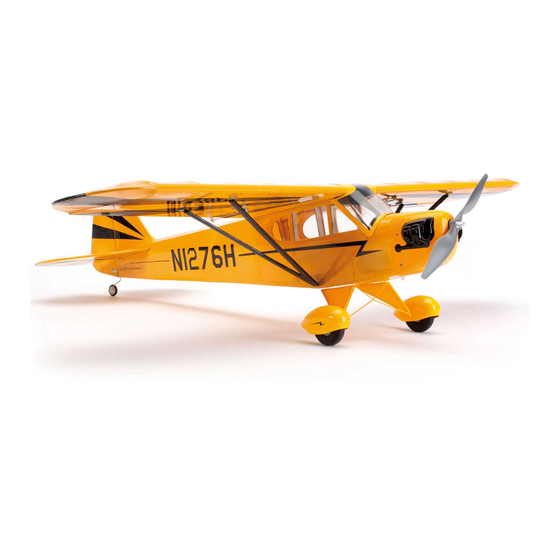
Non usare componenti non manuale. Usando componenti all’infuori di quell’elenco, si compatibili o alterare il prodotto in nessuna maniera al di fuori delle istruzioni fornite da Horizon Hobby, LLC. potrebbe dare un carico eccessivo alla struttura. Questo Questo kit comprende delle parti di piccole dimensioni Questo manuale contiene le istruzioni per un funzionamento e una manutenzione sicuri. - Page 6 SPECIFICATIONS•SPEZIFIKATIONEN• LARGE PARTS LAYOUT•BAUTEILE (OHNE KLEINTEILE)•GRANDES PIÈCES•SCHEMA DEI COMPONENTI GRANDI SPÉCIFICATIONS•SPECIFICHE 30.7 in (780mm) 168 sq in (10.9 dm2) 23.7 in (600mm) 8.95–9.30 oz (254–263 g) Electric Power Power: Power 250 Brushless Elektro Antrieb Power: Power 250 Brushless Moteur électrique (EP): Power 250 Brushless Motore elettrico: Power 250 Brushless...
- Page 7 REPLACEMENT PARTS•ERSATZTEILE•PIÈCES DE RECHANGE•PEZZI DI RICAMBIO Part English Deutsch Français Italiano EFL505501 Fuselage Rumpf Fuselage Fusoliera EFL505502 Wing Panels, Left and Right Tragfl ächen Aile gauche et droite Pannelli alari, Sinistro e Destro EFL505503 Tail Set Heck Empennages Set coda EFL505504 Landing Gear &...
- Page 8 REQUIRED ADHESIVES•ERFORDERLICHE KLEBSTOFFE•TYPES DE COLLES•ADESIVI NECESSARI PAAPT35 15-Minute Epoxy 15 Minuten Epoxy Époxy 15 minutes Colla epoxy 15 minuti PAAPT09 Thin CA Sekundenkleber dünnfl üssig Colle cyano fi ne Sottile CA PAAPT03 Medium CA Sekundenkleber mittel Colle cyano moyenne Medio CA PAAPT15 Zip Kicker Aerosol, 2 oz Zip Kicker Aerosol, 2 oz...
- Page 9 ASSEMBLY SYMBOL GUIDE•MONTAGE SYMBOLE•GUIDE DES SYMBOLES POUR ASSEMBLAGE•GUIDA AI SIMBOLI DI ASSEMBLAGGIO Use 15-minute epoxy Use hobby knife with #11 blade Assemble right and left Use medium CA Verwenden Sie 15 Minuten Epoxy Verwenden Sie ein Hobbymesser mit Links und rechts montieren Mittelfl...
-
Page 10: Before Starting Assembly
BEFORE STARTING ASSEMBLY VOR DEM ZUSAMMENBAU AVANT DE COMMENCER PRIMA DI INIZIARE IL MONTAGGIO L’ASSEMBLAGE • Remove parts from bag. • Entnehmen Sie zur Überprüfung jedes Teil der • Togliere tutti i pezzi dalla scatola. Verpackung. • Retirez toutes les pièces des sachets pour les •... - Page 11 RUDDER AND ELEVATOR SERVO INSTALLATION•EINBAU VON HÖHEN UND SEITENRUDERSERVO• INSTALLATION DES SERVOS DE PROFONDEUR ET DE DÉRIVE•INSTALLAZIONE SERVI TIMONE ED ELEVATORE Use the radio system to center the rudder and elevator servos. Install the servo arm on the servo as well as the servo mount.
- Page 12 M2 x 4 Secure the rudder and elevator servos in the fuselage with the servo output facing toward the rear of the fuselage. Center the rudder and rudder servo. Use the M2 x Schrauben Sie das Seitenruder- und Höhenruderservo 4 machine screw to secure the pushrod wire to the mit dem Abtrieb zum Heck zeigend in den Rumpf ein.
- Page 13 LANDING GEAR INSTALLATION• MONTAGE DES FAHRWERK• INSTALLATION DU TRAIN D’ATTERRISSAGE• INSTALLAZIONE DEL CARRELLO DI ATTERRAGGIO Lightly sand the inside of the wheel pants around the Lightly sand the wheel pant spacers in preparation for hole in the sides of the pant. Sand both the left and right their installation.
- Page 14 Slide the wheel pant on the landing gear. Slide the spacer Slide the wheel on the wire, then the plastic wheel With both wheel pants positioned, rest the fuselage on its Slide the wheel pant spacers against the inside edges on the wire and then the plastic wheel collar.
- Page 15 Use care when gluing the wheel pant MOTOR INSTALLATION•MOTOREINBAU• spacers and plastic wheel collars. You can INSTALLATION DU MOTEUR•INSTALLAZIONE DEL MOTORE easily get glue in the wheel, preventing it from rotating on the landing gear wire. Sein Sie bitte vorsichtig bei der Verklebung, da Sie ungewollt auch das Rad verkleben können.
- Page 16 COWLING INSTALLATION• EINBAU MOTORHAUBE• INSTALLATION DU CAPOT• INSTALLAZIONE CAPOTTINA MOTORE Guide the lead for the speed control connection to the Fit the speed control into the motor box. Connect the leads receiver through one of the square holes in the sub fi rewall. from the motor to the speed control.
- Page 17 Slide the cowling and propeller adapter into position. Check the position of the cowling to make sure the Check that the adapter is centered into the hole at the battery hatch can be removed without interference from front of the cowling. the cowling and the prop adapter base is slightly in front Cut four pieces of paper 1/4 inch (6mm) wide.
-
Page 18: Information Importante Concernant Votre Hélice
Important Information About Your Propeller Always ensure the propeller is balanced CAUTION: Never check the motor before installing it onto the shaft. An unbalanced rotation on the bench with the propeller propeller may cause poor flight characteristics. installed. The plane could move and cause Wichtige Information über ihren Propeller serious injury. - Page 19 RECEIVER AND MOTOR BATTERY INSTALLATION• AKKU UND EMPFÄNGEREINBAU• INSTALLATION DE LA BATTERIE ET DU RÉCEPTEUR• INSTALLAZIONE DEL RICEVITORE E DELLA BATTERIA MOTORE Remove the battery cover from the fuselage by lifting at Connect the leads from the rudder and elevator servos the tab at the front of the cover to release the magnets.
- Page 20 Secure the receiver using two-sided tape and/or silicone adhesive. Use the opening in the plate inside the fuselage to help align the receiver. Allow the adhesive to fully cure Route the aileron extensions through the openings in the Glue the front windscreen braces in position. The braces Carefully trim the windscreen to clear the airfoil of the wing.
- Page 21 Use clear tape to hold the windscreen on. This will allow The observation window can also be installed using clear Apply the loop tape on the battery. Use care not to cover Apply the hook tape in the fuselage as shown. future access inside the fuselage if needed to get back tape at this time.
- Page 22 AILERON SERVO INSTALLATION•EINBAU DER QUERRUDERSERVOS• INSTALLATION DES SERVOS D’AILERONS•INSTALLAZIONE SERVO ALETTONI Place the battery cover back into position on the bottom of the fuselage. Setzen Sie die Abdeckung wieder auf die Unterseite Use the radio system to center the aileron servos. Install des Rumpfes.
- Page 23 M2 x 4 M1.5 x 5 Secure a 3-inch (75mm) extension to the servo lead Prepare the holes in the wing for the cover mounting Insert the bend in the 2 inch (55mm) aileron pushrod using string or dental fl oss. screws by threading the screws into position.
- Page 24 WING INSTALLATION•MONTAGE DER TRAGFLÄCHEN•INSTALLATION DE L’AILE•MONTAGGIO DELL’ALA NOTICE: Do not cut into the underlying wood. This will weaken the structure and could cause failure in flight. As an option, use a soldering iron or hot knife with light pressure to carefully melt the covering and avoid the potential of cutting into the wood.
- Page 25 Fit the wing panels back to the fuselage. Use a paper towel and rubbing alcohol to remove any epoxy that may have oozed between the wing and fuselage. Use low-tack Apply a small amount of epoxy to the end of the tape to hold the wing panels tightly against the fuselage wing joiner rod.
-
Page 26: Center Of Gravity
CENTER OF GRAVITY DER SCHWERPUNKT CENTRE DE GRAVITÉ CENTRO DI GRAVITA’ (BARICENTRO) An important part of preparing the aircraft for fl ight is Ein sehr wichtiger Teil in der Flugvorbereitung ist es das Une des étapes importantes de la préparation d’un Un punto importante per preparare l’aereo al volo è... -
Page 27: Control Throws
CONTROL THROWS RUDERAUSSCHLÄGE 1. Turn on the transmitter and receiver of your model. Check the movement of the rudder using the transmitter. 1. Schalten Sie den Sender und Empfänger ihres Modells ein. Prüfen Sie die Seitenruderaussschläge mit dem Sender. When the stick is moved to the right, the rudder should also move right. Reverse the direction of the servo at the Bewegen Sie den Seitenruderstick nach rechts, sollte sich das Ruder auch nach rechts bewegen. -
Page 28: Débattements
DÉBATTEMENTS CORSE DEI COMANDI 1. Mettez l’émetteur et le récepteur sous tension. Contrôlez les mouvements de la dérive en utilisant votre émetteur. 1. Accendere trasmettitore e ricevitore del modello. Controllare i movimenti del timone agendo sul trasmettitore. Quand le manche est vers la droite, la dérive doit s’orienter vers la droite. Inversez la direction du servo à l’émetteur Quando lo stick va a destra, anche il timone deve andare a destra. -
Page 29: Preflight Checklist
PREFLIGHT CHECKLIST VORFLUGKONTROLLE CHECKLIST D’AVANT VOL LISTA DEI CONTROLLI PRIMA DEL VOLO • Charge the transmitter, receiver and motor • Laden Sie den Sender- ,Empfänger- und Zündakku • Chargez la batterie de votre émetteur, de réception • Caricare le batterie di trasmettitore, ricevitore battery for your airplane. -
Page 30: Daily Flight Checks
DAILY FLIGHT CHECKS TÄGLICHER FLUG CHECK CONTRÔLES SYSTÉMATIQUES CONTROLLI DI VOLO GIORNALIERI • Check the battery voltage of the transmitter battery. • Überprüfen Sie die Spannung des Senderakkus. • Contrôlez la tension de la batterie de l’émetteur. • Controllare la tensione della batteria del Do not fl... - Page 31 Limitation of Liability Inspection or Services Non-Warranty Service Horizon Hobby, LLC. (“Horizon”) warrants to the original HORIZON SHALL NOT BE LIABLE FOR SPECIAL, If this Product needs to be inspected or serviced and Should your service not be covered by purchaser that the product purchased (the “Product”)
-
Page 32: Garantie Und Service Informationen
Liegt eine kostenpfl ichtige Reparatur vor, erstellen enthält Sicherheitshinweise und Vorschriften sowie wurden aus. Rücksendungen durch den Käufer direkt an Exklusive Garantie ¬ Horizon Hobby LLC (Horizon) wir einen Kostenvoranschlag, den wir Ihrem Händler Hinweise für die Wartung und den Betrieb des Horizon oder eine seiner Landesvertretung bedürfen der... -
Page 33: Garantie Et Réparations
Questions, assistance et réparations Réparations payantes montage ou d’une manipulation erronés, d’accidents Garantie exclusive - Horizon Hobby, LLC. (Horizon) Votre revendeur spécialisé local et le point de vente En cas de réparation payante, nous établissons un devis ou encore du fonctionnement ainsi que des tentatives garantit que le Produit acheté... - Page 34 Periodo di garanzia Limiti di danno Manutenzione e riparazione La garanzia esclusiva - Horizon Hobby, LLC., (Horizon) Horizon non si riterrà responsabile per danni speciali, Se il prodotto deve essere ispezionato o riparato, garantisce che i prodotti acquistati (il “Prodotto”) sono diretti, indiretti o consequenziali;...
-
Page 35: Instructions For Disposal Of Weee By Users In The European Union
Harlow, Essex, CM18 7NS, United Kingdom +44 (0) 1279 641 097 Horizon Technischer Service service@horizonhobby.de Christian-Junge-Straße 1 Germany 25337 Elmshorn, Germany Sales: Horizon Hobby GmbH +49 (0) 4121 2655 100 infofrance@horizonhobby.com Service/Parts/Sales: 11 Rue Georges Charpak France Horizon Hobby SAS... - Page 36 ACADEMY OF MODEL AERONAUTICS NATIONAL MODEL AIRCRAFT SAFETY CODE Effective January 1, 2014 EXCEPTIONS: 3. At all fl ying sites a safety line(s) must be C. FREE FLIGHT established in front of which all fl ying takes place. A. GENERAL: A model aircraft is a non-human- •...
- Page 37 EFL Clipped Wing Cub...
- Page 38 EFL Clipped Wing Cub...
- Page 39 EFL Clipped Wing Cub...
- Page 40 © 2014 Horizon Hobby, LLC. E-fl ite, AS3X, Prophet, Precept, DSMX, the DSMX logo and the Horizon Hobby logo are trademarks or registered trademarks of Horizon Hobby, LLC. The Spektrum trademark is used with permission of Bachmann Industries, Inc. All other trademarks, service marks and logos are the property of their respective owners.