Publicité

Les langues disponibles
  • FR

Les langues disponibles

  • FRANÇAIS, page 39

Liens rapides

Ventilinsel / Valve terminal
CPVSC−DN DeviceNet
Kurz−
beschreibung
Brief description
Ventilinsel
Feldbus−Direkt
Typ CPVSC−DN
Valve terminal
Fieldbus Direct
Type CPVSC−DN
Deutsch
English
Español
Français
Italiano
Svenska
690 387
0412a

Publicité

Table des Matières
loading

Sommaire des Matières pour Festo CPVSC-DN

  • Page 1 Ventilinsel / Valve terminal CPVSC−DN DeviceNet Kurz− beschreibung Brief description Ventilinsel Feldbus−Direkt Typ CPVSC−DN Valve terminal Fieldbus Direct Type CPVSC−DN Deutsch English Español Français Italiano Svenska 690 387 0412a...
  • Page 2 ......... . . Edition: 0412a Original: de © (Festo AG & Co. KG, D 73726 Esslingen, Germany, 2004) Internet: http://www.festo.com E−Mail: service_international@festo.com 0412a Festo CPVSC−DN...
  • Page 3 Sie zusätzlich die allgemeinen Anforderungen an PELV−Stromkreise gemäß IEC/DIN EN60204−1. S Erden Sie die Ventilinsel am Erdungsanschluss des Gehäuses und über Pin 5 (Schirm) der Spannungs versorgung. S Nehmen Sie nur ein komplett montiertes und ver drahtetes CP−System in Betrieb. 0412a Festo CPVSC−DN Deutsch...
  • Page 4: Anschluss− Und Bedienelemente

    Anschluss− und Bedienelemente Abdeckung für IP40 Erdungsanschluss Schaltzustands− anzeige Ventilspulen Anschluss für CP−Erweiterung Anschluss für Spannungsversorgung Anschluss für Feldbus DIL−Schalter für CP−Erweiterung Drehschalter für Baudrate Drehschalter für Stationsnummer 0412a Festo CPVSC−DN Deutsch...
  • Page 5 5: FE 2.2 Anschlussbeispiel mit galvanischer Trennung von Betriebs− und Lastspannung Netzteil für Lastspannung 3 4 1 2 (Ventile und Ausgänge) Einrichtung zur Isola− tionsüberwachung Lastspannung getrennt abschaltbar und externe Sicherungen Netzteil für Betriebsspannung (Elektronik und Sensorik) 0412a Festo CPVSC−DN Deutsch...
  • Page 6 3: 0 V Bus (schwarz) 4: CAN_H (weiß) 5: CAN_L (blau) 2.4 LEDs Bedeutung Power System": Spannungsversorgung Elektronik (und Sensorik in einem CP−Eingangsmodul) Power Load": Spannungsversorgung Ventile (und Ventile/Ausgänge im CP−Erweiterungsstrang) CP−Systemfehler Netzwerkstatus DeviceNet Modulstatus DeviceNet 0412a Festo CPVSC−DN Deutsch...
  • Page 7: Konfiguration

    S Stellen Sie sicher, dass Einschalt−Testimpulse unter drückt werden, wenn Sie die CPVSC−DN über ein Sicherheitsgerichtetes EA−Modul" betreiben. S Prüfen Sie, mit welchen Maßnahmen Sie Ihre Anlage im NOT−AUS−Fall in einen sicheren Zustand versetzen. Weitere Informationen: Beschreibung P.BE−CPASC−CPVSC−DN−.. 0412a Festo CPVSC−DN Deutsch...
  • Page 8 LSD (least significant digit) stellen Sie die Feldbus− Stationsnummer (MAC ID, Slave address) ein. Zulässig sind Stationsnummern zwischen 0 und 63. Beispiele: Stationsnummer: 05 Stationsnummer: 38 3.2 Feldbus−Baudrate einstellen 125 kBaud 250 kBaud 500 kBaud Die automatische Baudratenerkennung P wird nicht unterstützt. 0412a Festo CPVSC−DN Deutsch...
  • Page 9 5. Setzen Sie DIL1 zunächst auf OFF zurück und dann wieder auf ON. Das CP−System ist nun konfiguriert und lauffähig (LED SF ist aus). Bei Änderungen an der CP−Erweiterung: 6. Starten Sie den Erkennungsvorgang neu (Punkte 1...5). 0412a Festo CPVSC−DN Deutsch...
  • Page 10 CP−Erweiterungsstrang belegen je 16 Aus gangs− oder Eingangsadressen. Monostabile Ventile, belegen jeweils einen Ventilplatz Impulsventile, belegen jeweils zwei Ventilplätze Ausführliche Angaben und Beispiele zur Adressierung des CP−Systems finden Sie in der Beschreibung P.BE−CPASC−CPVSC−DN−.. . 0412a Festo CPVSC−DN Deutsch...
  • Page 11 Demontage eines vorhandenen Knotens 1. Schraube 1 auf der Unterseite herausdrehen. 2. Feldbusknoten etwas nach oben drücken, um den internen Haken 2 auszurasten. 3. Feldbusknoten oben von der Ventilinsel wegschwenken, ohne das Flachbandkabel 3 mechanisch zu belasten. 0412a Festo CPVSC−DN Deutsch...
  • Page 12 Haken 2 einrastet. 2. Schraube 1 (Lage siehe De montage, Schritt 1) mit 0,5 Nm (±10%) festdrehen. 3. Stecker des Flachbandkabels 5 auf der Unterseite der Ventilinsel in die Führung einschieben, bis die Sicherungshaken 4 einrasten. 0412a Festo CPVSC−DN Deutsch...
  • Page 13: Technische Daten

    Schutzart nach EN 60529 IP40 (bei Wandmontage und Abdeckung oder Aufkleber über Dreh− und DIL−Schaltern) Elektromagnetische Verträglichkeit Störaussendung Geprüft nach EN 61000−6−4 (Industrie) Störfestigkeit Geprüft nach EN 61000−6−2 (Industrie) Ventile Siehe Pneumatik− Beschreibung P.BE−CPVSC−.. 0412a Festo CPVSC−DN Deutsch...
  • Page 14 Schlag sen (Schutz gegen direktes und indirek tes Berühren gemäß IEC/DIN EN60204−1) Galvanische Trennung Feldbus−Schnittstelle: optoentkoppelt von Spannungsversorgungsanschluss Spannungsversorgungsanschluss: Pin1 galvanisch getrennt von Pin2 Ausführliche Informationen über die CPVSC−DN erhalten Sie in der Beschreibung P.BE−CPASC−CPVSC−DN−.. . 0412a Festo CPVSC−DN Deutsch...
  • Page 15 PELV circuits in accordance with IEC/DIN EN60204−1. S Earth the valve terminal at the earth connection on the housing and via pin 5 (screening/shield) for the power supply. S Commission only a CP system which is fitted and wired completely. 0412a Festo CPVSC−DN English...
  • Page 16 Cover for IP40 Earth/ground connection Switching status display for valve coils Connection for CP extension Connection for power supply Connection for field bus DIL switch for CP extension Rotary switch for baud rate Rotary switch for station number 0412a Festo CPVSC−DN English...
  • Page 17 Power unit for load voltage (valves and 3 4 1 2 outputs) Device for isolation monitoring 24 V Load voltage can be switched off separately and external fuses 24 V Power unit for operating voltage (electronics and sensors) 0412a Festo CPVSC−DN English...
  • Page 18 Power System": Power supply for the electronics (and sensors in a CP input module) Power Load": Power supply for the valves (and valves/ outputs in the CP extension string) CP system error Network status DeviceNet Module status DeviceNet 0412a Festo CPVSC−DN English...
  • Page 19: Configuration

    S Make sure that switch−on test pulses are suppressed if you are operating the CPVSC−DN via a Fail safe I/O module". S Check the measures for putting the system into a safe state in the event of an EMERGENCY STOP. Further information: Manual P.BE−CPASC−CPVSC−DN−... 0412a Festo CPVSC−DN English...
  • Page 20 LSD (least significant digit). Station numbers between 0 and 63 are permitted. Examples: Station number: 05 Station number: 38 3.2 Setting the field bus baud rate 125 kBaud 250 kBaud 500 kBaud The automatic baud rate recognition P is not supported. 0412a Festo CPVSC−DN English...
  • Page 21 5. Set DIL1 at first to OFF and then to ON again. The CP system is now configured and ready to run (LED SF is out). If modifications have been made to the CP extension: 6. Start the recognition procedure again (points 1 ... 5). 0412a Festo CPVSC−DN English...
  • Page 22 CP extension string each occupy 16 input or output addresses. Single−solenoid valves, occupy one valve location each Double−solenoid valves, occupy two valve locations each Detailed information and examples of addressing the CP system can be found in the manual P.BE−CPASC−CPVSC−DN−..0412a Festo CPVSC−DN English...
  • Page 23 2. Press the field bus node upwards a little so that the internal hook 2 unlocks. 3. Push the field bus node upwards away from the valve terminal without mechanically stressing the ribbon cable 3. 0412a Festo CPVSC−DN English...
  • Page 24 2. Tighten screw 1 (position see Dismantling, Step 1) with 0.5 Nm (±10%). 3. Push the plug of the ribbon cable 5 on the base of the valve terminal into the guide until the locking hooks 4 lock into position. 0412a Festo CPVSC−DN English...
  • Page 25: Technical Specifications

    IP40 (if fitted on a wall with cover or sticker on the rotary or DIL switches) Electromagnetic compatibility Interference emitted Tested as per EN 61000−6−4 (industry) Immunity against interference Tested as per EN 61000−6−2 (industry) Valves See Pneumatics manual P.BE−CPVSC−.. 0412a Festo CPVSC−DN English...
  • Page 26: Power Supply

    IEC/DIN EN60204−1) Electrical isolation Field bus interface: opto−uncoupled from the power supply connection Power supply connection: pin 1 electrically isolated from pin 2 Detailed information about the CPVSC−DN can be found in the manual P.BE−CPASC−CPVSC−DN−..0412a Festo CPVSC−DN English...
  • Page 27: Instrucciones Para El

    S Poner a tierra el terminal de válvulas con la conexión de tierra que hay en el cuerpo y a través del pin 5 (apantallamiento/blindaje) para la fuente de alimen tación. S Poner a punto un sistema CP sólo cuando se halle completamente montado y cableado. 0412a Festo CPVSC−DN Español...
  • Page 28 Conexión para ampliación CP Conexión para alimentación Conexión para bus de campo Interruptor DIL para la ampliación CP Interruptor giratorio para la velocidad de transmisión Interruptor giratorio para el número de estación 0412a Festo CPVSC−DN Español...
  • Page 29 (válvulas y salidas) Dispositivo para 24 V supervisión del aislamiento Tensión de carga puede desconectarse por separado y tener 24 V fusibles externos Fuente de alimenta− ción para la tensión de funcionamiento (electrónica y sensores) 0412a Festo CPVSC−DN Español...
  • Page 30 (y sensores en un módulo de entradas CP) Power Load": Alimentación de tensión para las válvulas (y válvulas/salidas en el ramal de ampliación CP) Error del sistema CP Estado de la red DeviceNet Estado del módulo DeviceNet 0412a Festo CPVSC−DN Español...
  • Page 31 CPVSC−DN a través de un módulo de I/O de seguridad (Fail safe). S Compruebe las medidas requeridas para poner el sistema en un estado de seguridad en el caso de un PARO DE EMERGENCIA. Otras informaciones: Manual P.BE−CPASC−CPVSC−DN−... 0412a Festo CPVSC−DN Español...
  • Page 32 Ejemplos: Número de estación: 05 Número de estación: 38 3.2 Ajuste de la velocidad de transmisión del bus 125 kBaud 250 kBaud 500 kBaud No está soportado el reconocimiento automático P de la velocidad de transmisión. 0412a Festo CPVSC−DN Español...
  • Page 33 El sistema CP está ahora configurado y prepa rado para funcionar (el LED LF está apagado). Si se han hecho modificaciones en la ampliación del CP: 6. Iniciar de nuevo el procedimiento de reconocimiento (puntos 1 ... 5). 0412a Festo CPVSC−DN Español...
  • Page 34 Las válvulas de simple bobina ocupan siempre una posición de válvula cada una Las válvulas de doble bobina ocupan dos posiciones de válvula cada una En el manual P.BE−CPASC−CPVSC−DN−... puede hallarse infor mación y ejemplos de direccionamiento del sistema CP. 0412a Festo CPVSC−DN Español...
  • Page 35 2. Empuje un poco hacia arriba el nodo de bus de campo a fin de desbloquear el gancho interno 3. Tire del nodo de bus de campo alejándolo del terminal de vál vulas sin forzar mecánicamente el cable plano 3. 0412a Festo CPVSC−DN Español...
  • Page 36 1) con 0,5 Nm (±10%). 3. Empuje la clavija del cable plano 5 en la base del terminal de válvulas en la guía hasta que los ganchos 4 lo bloqueen en su posición. 0412a Festo CPVSC−DN Español...
  • Page 37: Especificaciones Técnicas

    DIL) Compatibilidad electromagnética Emisión de interferencias Verificada según EN 61000−6−4 (industria) Inmunidad ante interferencias Verificada según EN 61000−6−2 (industria) Válvulas Véase el manual de la parte neumática P.BE−CPVSC−... 0412a Festo CPVSC−DN Español...
  • Page 38 Aislamiento eléctrico Interface del bus de campo: opto−desacoplado de la conexión de alimentación de tensión Conexión de alimentación: pin 1 eléctricamente aislado del pin 2 Puede hallarse información detallada sobre el CPVSC−DN en el manual P.BE−CPASC−CPVSC−DN−..0412a Festo CPVSC−DN Español...
  • Page 39: Français

    S Relier le terminal de distributeurs à la borne de terre du boîtier et via la broche 5 (blindage) de l’alimenta tion électrique. S Ne mettre le système CP en service que lorsque le montage et le raccordement sont totalement terminés. 0412a Festo CPVSC−DN Français...
  • Page 40: Eléments De Raccordement Et De Commande

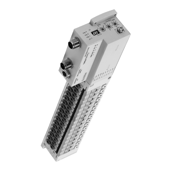
    Affichage de l’état de commutation des bobines de distributeur Connecteur pour l’extension CP Connecteur d’alimentation Connecteur pour le bus de terrain Interrupteur DIL pour l’extension CP Potentiomètre pour la vitesse de transmission Potentiomètre pour le numéro de station 0412a Festo CPVSC−DN Français...
  • Page 41: Affectation Des Broches : Alimentation Électrique

    (distributeurs et 3 4 1 2 sorties) Dispositif pour la surveillance de 24 V l’isolation Tension de puissance pouvant être coupée séparément et fusibles externes 24 V Bloc d’alimentation pour l’alimentation de service (électro− nique et capteurs) 0412a Festo CPVSC−DN Français...
  • Page 42: Affectation Des Broches : Connecteur De Bus De Terrain

    Power System" : Alimentation de l’électronique (et des capteurs dans un module d’entrées CP) Power Load" : Alimentation des distributeurs (et des distributeurs/sorties dans la branche d’extension CP) Erreur système CP Etat du réseau DeviceNet Etat du module DeviceNet 0412a Festo CPVSC−DN Français...
  • Page 43 CPVSC−DN fonctionne via un Module E/S de sécurité". S Veiller à prévoir les mesures nécessaires pour garantir la sécurité de l’installation en cas d’arrêt d’urgence. Pour de plus amples informations : manuel P.BE−CPASC−CPVSC−DN−... 0412a Festo CPVSC−DN Français...
  • Page 44: Réglage Du Numéro De Station

    Numéro de station : 05 Numéro de station : 38 3.2 Régler la vitesse de transmission du bus de terrain 125 kBaud 250 kBaud 500 kBaud La détection automatique de la vitesse de transmission P n’est pas prise en charge. 0412a Festo CPVSC−DN Français...
  • Page 45: Régler L'extension Du Système Cp

    5. Mettez d’abord DIL1 sur OFF puis de nouveau sur ON. Le système CP est maintenant configuré et prêt à fonctionner (la LED SF est coupé). En cas de modifications de l’extension CP : 6. Redémarrer l’opération de détection (points 1 ... 5). 0412a Festo CPVSC−DN Français...
  • Page 46: Adressage

    Les distributeurs monostables occupent chacun un emplacement de distributeur Les distributeurs bistables occupent chacun deux emplacements de distributeurs Vous trouverez des indications détaillées et des exemples d’adressage du système CP dans le manuel P.BE−CPASC−CPVSC−DN−..0412a Festo CPVSC−DN Français...
  • Page 47: Montage Et Démontage Des N Uds De Bus De Terrain

    1. Dévisser la vis 1 ) sur la face inférieure. 2. Pousser un peu le n ud vers le haut pour dégager le crochet interne 2. 3. Extraire le noeud en haut du terminal, sans charger mécaniquement le câble plat 3. 0412a Festo CPVSC−DN Français...
  • Page 48 Dé montage, étape 1) au couple de 0,5 Nm (±10 %). 3. Introduire le connecteur du câble plat 5 sur le dessous du terminal dans le guidage jusqu’à ce que les verrous de sécurité 4 s’enclenchent. 0412a Festo CPVSC−DN Français...
  • Page 49: Caractéristiques Techniques

    EN 60529 panneau, et de cache ou d’étiquette sur les interrupteurs rotatifs et DIL) Compatibilité électromagnétique Emission de perturbations Contrôlée selon EN 61000−6−4 (Industrie) Immunité aux perturbations Contrôlée selon EN 61000−6−2 (Industrie) Distributeurs Voir manuel Pneumatique P.BE−CPVSC−.. 0412a Festo CPVSC−DN Français...
  • Page 50: Alimentation Électrique

    Isolation galvanique Interface du bus de terrain : Isolé par optocoupleur. Alimentation : la broche 1 est isolée électriquement de la broche 2 De plus amples informations sur le CPVSC−DN figurent dans le manuel P.BE−CPASC−CPVSC−DN−..0412a Festo CPVSC−DN Français...
  • Page 51: Istruzioni Per

    S Effettuare la messa a terra dell’unità di valvole collegando la connessione di terra presente sul corpo e il pin 5 (schemo) del modulo di alimentazione di tensione. S Utilizzare solamente un sistema CP completamente assemblato e cablato. 0412a Festo CPVSC−DN Italiano...
  • Page 52 Placchetta IP40 Connessione di terra LED di segnalazione di stato dei solenoidi Connessione espansione sistema CP Connessione tensione di alimentazione Connettore bus di campo Interruttore DIL espansione sistema CP Selettore rotativo baudrate Selettore rotativo numero stazione 0412a Festo CPVSC−DN Italiano...
  • Page 53 3 4 1 2 (valvole e uscite) Dispositivo monitoraggio 24 V isolamento Con possibilità di disinserzione della tensione di carico e fusibili di sicurezza 24 V esterni Alimentatore tensione di esercizio (elettronica e sensori) 0412a Festo CPVSC−DN Italiano...
  • Page 54 (e dei sensori di un modulo di ingresso CP) Power Load": Alimentazione elettrica delle valvole (e di valvole e uscite nella linea di espansione CP) Errore di sistema CP Stato della rete DeviceNet Stato modulo DeviceNet 0412a Festo CPVSC−DN Italiano...
  • Page 55 S Assicurare che gli impulsi di prova inserzione ven gano soppressi in caso di azionamento dell’unità CPVSC−DN tramite un Modulo di sicurezza I/O". S Verificare la sicurezza di funzionamento dell’impianto in caso di emergenza. Per ulteriori informazioni si rimanda alla descrizione P.BE−CPASC−CPVSC−DN−..0412a Festo CPVSC−DN Italiano...
  • Page 56 0 e 63. Esempi: Numero di stazione: 05 Numero di stazione: 38 3.2 Impostazione del baudrate del bus di campo 125 kBaud 250 kBaud 500 kBaud Non è supportato il riconoscimento automatico del baudrate P. 0412a Festo CPVSC−DN Italiano...
  • Page 57 DIL dapprima su OFF, quindi ricommutarlo su ON. A questo punto il sistema CP è configurato e pronto (il LED SF è spento). Per eseguire modifiche dell’espansione del sistema CP: 6. Ripetere la procedura di riconoscimento (punti 1 ... 5). 0412a Festo CPVSC−DN Italiano...
  • Page 58 16 indirizzi di ingresso o uscita. Valvole monostabili, occupano un posto valvola ciascuna Valvole bistabili, occupano due posti valvola ciascuna Per informazioni ed esempi dettagliati sull’indirizzamento del sistema CP fare riferimento alla descrizione P.BE−CPASC−CPVSC−DN−..0412a Festo CPVSC−DN Italiano...
  • Page 59 1. Allentare ed estrarre la vite 1 sul lato inferiore. 2. Sollevare leggermente il nodo Fieldbus per liberare il gancio interno 2. 3. Estrarre il nodo Fieldbus dall’unità di valvole ruotan dolo, senza tirare eccessiva mente il cavo piatto 3. 0412a Festo CPVSC−DN Italiano...
  • Page 60 Smontaggio, passo 1) con 0,5 Nm (±10%). 3. Inserire il connettore del cavo piatto 5 nella guida presente sul lato inferiore dell’unità di valvole fino a fare scattare in posizione le linguette di sicu rezza 4. 0412a Festo CPVSC−DN Italiano...
  • Page 61: Dati Tecnici

    DIL) Compatibilità elettromagnetica Emissione di interferenze Misurata in conformità di EN 61000−6−4 (industriale) Immunità alle interferenze Misurata in conformità di EN 61000−6−2 (industriale) Valvole Fare riferimento alla descrizione della parte pneumatica P.BE−CPVSC−.. 0412a Festo CPVSC−DN Italiano...
  • Page 62: Alimentazione Elettrica

    Interfaccia bus di campo: separata dal connettore di alimentazione elettrica mediante disac coppiamento optoelettronico Connettore di alimentazione elettrica: pin 1 isolato galvanicamente dal pin 2 Per informazioni dettagliate sull’unità CPVSC−DN fare riferimento alla descrizione P.BE−CPASC−CPVSC−DN−..0412a Festo CPVSC−DN Italiano...
  • Page 63: Svenska

    IEC/DIN EN60204−1. Observera dessutom allmänna krav på PELV−kretsar enligt IEC/DIN EN60204−1. S Jorda ventilterminalen vid husets jordanslutning och via spänningsmatningens stift 5 (skärm). S Endast ett komplett monterat och anslutet CP−system får tas i drift. 0412a Festo CPVSC−DN Svenska...
  • Page 64 Anslutnings− och manöverdon Skydd för IP40 Jordanslutning Kopplingsläges− indikering ventilspolar Anslutning för CP−expansion Anslutning för spänningsmatning Anslutning för fältbuss DIL−omkopplare för CP−expansion Vridomkopplare för överföringshastighet Vridomkopplare för stationsnummer 0412a Festo CPVSC−DN Svenska...
  • Page 65 2.2 Anslutningsexempel med galvanisk isolering av matningsspänning Nätdel för matningsspänning 3 4 1 2 (ventiler och utgångar) Anordning för 24 V isoleringsöver− vakning Matningsspänning kan frånskiljas separat, externa 24 V säkringar Nätdel för matningsspänning (elektronik och ingångar) 0412a Festo CPVSC−DN Svenska...
  • Page 66 2: 24 VDC−buss (röd) 3: 0 V−buss (svart) 4: CAN_H (vit) 5: CAN_L (blå) 2.4 LED Betydelse Power System": Spänningsmatning elektronik (och givare i en CP−ingångsmodul) Power Load": Spänningsmatning ventiler (och ventiler/utgångar i CP−slingan) CP−systemfel Nätverksstatus DeviceNet Modulstatus DeviceNet 0412a Festo CPVSC−DN Svenska...
  • Page 67 S Säkerställ att testimpulserna vid tillkoppling är avstängda när CVPSC−DN är ansluten via en Säkerhets I/O−modul". S Kontrollera vilka åtgärder du bör vidta för att försätta din anläggning i ett säkert tillstånd vid nödstopp. Ytterligare information: Manual P.BE−CPASC−CPVSC−DN−... 0412a Festo CPVSC−DN Svenska...
  • Page 68 LSD (least significant digit) ställer du in fältbusstations− nummer (MAC ID, Slave address). Tillåtna stationsnummer ligger mellan 0 och 63. Exempel: Stationsnummer: 05 Stationsnummer: 38 3.2 Ställa in fältbussens överföringshastighet 125 kBaud 250 kBaud 500 kBaud Automatisk avkänning av överföringshastighet P stöds inte. 0412a Festo CPVSC−DN Svenska...
  • Page 69 5. Ställ därefter DIL1 i läge OFF och sedan i läge ON igen. CP−systemet är nu konfigurerat och körklart (LED SF är släckt). Vid ändringar av CP− expansionen: 6. Starta avkänningsförloppet på nytt (punkt 1 ... 5). 0412a Festo CPVSC−DN Svenska...
  • Page 70 2. CP−ventilterminaler och elektriska utgångs− eller ingångsmoduler på CP−slingan belägger vardera 16 utgångs− eller ingångsadresser. Monostabila ventiler, belägger en ventilplats var Bistabila ventiler, belägger två ventilplatser var Utförliga uppgifter och exempel på adressering av CP−systemet finns i manualen P.BE−CPASC−CPVSC−DN−..0412a Festo CPVSC−DN Svenska...
  • Page 71 Demontering av en befintlig nod 1. Skruva ut skruven 1 på undersidan. 2. Tryck fältbussnoden något uppåt, för att lossa den inre haken 2. 3. Sväng bort fältbussnoden ovanför ventilterminalen, utan att belasta flatbandskabeln 3 mekaniskt. 0412a Festo CPVSC−DN Svenska...
  • Page 72 2 låses fast. 2. Dra åt skruven 1 (läge se demontering, steg 1) med 0,5 Nm (±10 %). 3. Skjut in flatbandskabelns kontakt 5 på undersidan av ventilterminalen i styrskenan tills spärrhakarna 4 låses fast. 0412a Festo CPVSC−DN Svenska...
  • Page 73: Tekniska Data

    90 % vid 50 °C, ej kondenserande Kapslingsklass enligt EN 60529 IP40 (vid väggmontering, med skydd eller etikett ovanför vrid− och DIL−omkopplare) Elektromagnetisk kompatibilitet Radiostörning Kontrollerad enligt EN 61000−4 (industri) Immunitet Kontrollerad enligt EN 61000−2 (industri) Ventiler Se pneumatikmanual P.BE−CPVSC−... 0412a Festo CPVSC−DN Svenska...
  • Page 74 (skydd mot direkt eller indirekt beröring enligt IEC/DIN EN60204−1) Galvanisk isolering Fältbussgränssnitt: optoisolerat från anslutningen för spänningsmatning Anslutning för spänningsmatning: stift 1 galvaniskt isolerat från stift 2 Utförlig information om CPVSC−DN finns i manualen P.BE−CPASC−CPVSC−DN−..0412a Festo CPVSC−DN Svenska...

Ce manuel est également adapté pour:

Cpvsc-dn devicenet

Table des Matières