Table des Matières

Publicité

Les langues disponibles

Les langues disponibles

Liens rapides

Helios Ventilatoren
MONTAGE- UND BETRIEBSVORSCHRIFT
INSTALLATION AND OPERATING INSTRUCTIONS
NOTICE DE MONTAGE ET D'UTILISATION
Kompakte Wandgeräte mit easyControls
Compact wall-mounted units with easyControls
Centrale murale compacte avec easyControls
KWL EC 170 W
KWL EC 170 W ET
Wärmerückgewinnung und EC-Technik für zentrale
Be- und Entlüftung
Heat recovery and EC technology for central
supply and extract ventilation
Ventilation double flux centralisée avec récupération
de chaleur et technologie EC
DE
EN
FR

Publicité

Table des Matières
loading

Sommaire des Matières pour Helios KWL EC 170 W

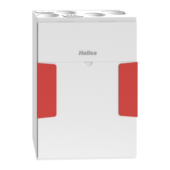
  • Page 1 Kompakte Wandgeräte mit easyControls Compact wall-mounted units with easyControls Centrale murale compacte avec easyControls KWL EC 170 W KWL EC 170 W ET Wärmerückgewinnung und EC-Technik für zentrale Be- und Entlüftung Heat recovery and EC technology for central supply and extract ventilation Ventilation double flux centralisée avec récupération...
  • Page 2: Table Des Matières

    Verdrahtungsplan KWL EC 170 W / W ET ....... . .
  • Page 3: Allgemeine Informationen

    Erwerb eines Premiumproduktes von Helios Ventilatoren. Als Helios Kunde profitieren Sie von der langjährigen Erfahrung des Unternehmens in der Bran- che und erhalten einen Artikel in Premiumqualität. Alle KWL EC 170 W / W ET Geräte werden bereits bei der Produktion auf ihre Funktionsfähigkeit geprüft.
  • Page 4: Einsatzbereich - Anwendung

    1 .8 Einsatzbereich – Anwendung Kompaktgeräte KWL EC 170 W / W ET mit Wärmerückgewinnung, für die zentrale Be- und Entlüftung von Wohnhäu- sern und Etagenwohnungen. Ausgestattet mit easyControls, dem innovativen Steuerungskonzept für einfachste Netz- werkanbindung und Webbrowser-Bedienung. Mit hoch effizientem Kreuzgegenstrom-Wärmetauscher aus Kunststoff, mit einem Wärmebereitstellungsgrad von, siehe Tabelle:...
  • Page 5: Technische Daten

    Montage- und Betriebsvorschrift Kompakte Wandgeräte KWL EC 170 W / W ET 1 .12 Technische Daten KWL EC 170 W / W ET Spannung/Frequenz 1~ 230 V~/50 Hz Nennstrom – Lüftungsbetrieb 0,4 A Nennstrom – Vorheizung 4,4 A Nennstrom – max. gesamt 0,4 A (4,8 inkl .
  • Page 6: Wichtige Gerätekomponenten

    Montage- und Betriebsvorschrift Kompakte Wandgeräte KWL EC 170 W / W ET 1 .14 Wichtige Gerätekomponenten Abb .2 Pos . Benennung Pos . Benennung Zuluftventilatoreinheit Siphon Abluftventilator Verschlussdeckel Zuluft Zu- und Abluft-Filterabdeckungen Steuerung Filterblende RJ Adapter Platine Tür Wandhalterung Rückwand...
  • Page 7: Gerät An Aufstellbedingungen Anpassen

    Montage- und Betriebsvorschrift Kompakte Wandgeräte KWL EC 170 W / W ET 2 .1 Gerät an Aufstellbedingungen anpassen Die Außenluftseite des KWL Gerätes lässt sich je nach Bedarf anpassen. Darüber hinaus kann die Zuluftversorgung wahlweise oben oder unten am Gerät erfolgen.
  • Page 8: Kondensatablauf

    Montage- und Betriebsvorschrift Kompakte Wandgeräte KWL EC 170 W / W ET Abb .5 Abb .6 KWL-Gerät Wandschiene 2 .3 Kondensatablauf Während der Heizperiode kondensiert die Feuchtigkeit der Abluft zu Wasser. In Neubauten oder bei Tätigkeiten wie z.B. Kochen, Wäschetrocknen oder Baden, kann sich reichlich Kondenswasser bilden. Dieses Kondenswasser muss frei aus dem Gerät ablaufen können.
  • Page 9: Anschlussmuffen

    Montage- und Betriebsvorschrift Kompakte Wandgeräte KWL EC 170 W / W ET Abb .12 Abb .13 Siphon-Gehäuse aufstecken 1/4 Drehung Kondensatschlauch DN 12 mm (Gefälle beachten!) 5. Siphon-Gehäuse aufstecken und mit 1/4 Drehung im Abb .14 Befestigungsteil einrasten (Abb.12) HINWEIS: Darauf achten, dass die Schwimmer-Kugel WICHTIG lose im Gehäuse liegt!
  • Page 10: Gerätedämmung

    Montage- und Betriebsvorschrift Kompakte Wandgeräte KWL EC 170 W / W ET hen werden. Bei Absaugung von verschmutzter Abluft ist ein Filter (Zubehör) vorzuschalten. Dunstabzugshauben dür- fen nicht an das System angeschlossen werden (Gründe: Schmutz, Brandgefahr, Hygiene). Zur Sicherstellung der Luft- führung innerhalb der Raumeinheit sind ausreichende Überströmöffnungen (Türspalte, Türlüftungsgitter) vorzusehen.
  • Page 11: Funktionsschema

    In den Helios-Praxisworkshops wird die Einregulierung mittels Druckmessung erklärt. Dies ist die einfachste Möglich- keit, ein KWL EC 170 W / W ET einzuregeln. Hierfür muss an jedem Anschlussstutzen/Lüftungsrohr (ca. 20 cm nach dem Geräteanschluss) jeweils ein Druckmessstutzen montiert werden, die Druckschläuche müssen zugänglich verlegt sein.
  • Page 12: Filterwechsel

    Montage- und Betriebsvorschrift Kompakte Wandgeräte KWL EC 170 W / W ET 3 .0 Filterwechsel KAPITEL 3 Zum Wechseln der Filter, die Filterblende nach oben aushängen und die Zu- und Abluft-Filterabdeckungen entfernen. Anschließend die Filter herausziehen und durch Ersatzluftfilter ersetzten.
  • Page 13: Kondensatablauf Im Gerät

    Montage- und Betriebsvorschrift Kompakte Wandgeräte KWL EC 170 W / W ET 3 .2 Kondensatablauf im Gerät Bei Wartungsmaßnahmen sicherstellen, dass der Kugelsiphon in der Bodenwanne des Gerätes nicht verstopft ist (Punkt 2.3). Dies kann durch Eingießen einer kleinen Menge Wasser in den Siphon überprüft werden.
  • Page 14: Sonstiges Zubehör

    Montage- und Betriebsvorschrift Kompakte Wandgeräte KWL EC 170 W / W ET 3 .5 Sonstiges Zubehör KWL-BE Best.-Nr. 4265 Bedienelement Schiebeschalter (Unterputz) mit Betriebsanzeige KWL-BEC Best.-Nr. 4263 Bedienelement Komfort (Unterputz) mit 3 m Anschlussleitung KWL-APG Best.-Nr. 4270 Aufputzgehäuse Best.-Nr. 4269...
  • Page 15: Standard Anschlussplan Ss-1042

    Montage- und Betriebsvorschrift Kompakte Wandgeräte KWL EC 170 W / W ET 5 .0 Standard Anschlussplan SS-1042 KAPITEL 5 Abb .26 SCHALTPLAN VERDRAHTUNGSPLAN...
  • Page 16 Montage- und Betriebsvorschrift Kompakte Wandgeräte KWL EC 170 W / W ET 5 .1 Verdrahtungsplan für KWL EC 170 W / W ET Abb .27 Geräte Zuleitung, 2 m 3 x 1,5 mm², 230 V~ RJ-45 RJ-12 RJ-10 PI N...
  • Page 17: Gerätetypenschild

    Montage- und Betriebsvorschrift Kompakte Wandgeräte KWL EC 170 W / W ET 5 .2 Gerätetypenschild Technischen Daten des KWL-Geräts sind dem Gerätetypenschild zu entnehmen. Typenschildbeispiel Abb .28 00912001.h Zeichenschlüssel Typenschild: Herstelleradresse Spannungsbereich [V] Ausführung: Temperatur KWL EC = Typenbezeichnung Nennleistung Vorheizung [kW] 170 = Baugröße...
  • Page 18 Wiring plan KWL EC 170 W / W ET ....... .
  • Page 19: General Information

    You have chosen a product from Helios Ventilatoren. This means that you have purchased a premium product and you will benefit from our many years of experience. All KWL EC 170 W / W ET units have been tested at every stage of production. Not only has the obvious function (e.g. the fans running) been tested, but also the functions which you, as the customer, cannot test.
  • Page 20: Application - Operation

    1 .8 Application – Operation KWL EC 170 W / W ET compact units with heat recovery, for the central ventilation of houses and apartments. Equip- ped with easyControls, the innovative control concept for simpler network connection and web browser operation.
  • Page 21: Technical Data

    Installation and Operating Instructions Compact wall-mounted units KWL EC 170 W / W ET 1 .12 Technical data KWL EC 170 W / W ET Voltage/Frequency 1~ 230 V~/50 Hz Rated current – ventilation 0 .4 A Rated current – pre-heater 4 .4 A...
  • Page 22: Important Unit Components

    Installation and Operating Instructions Compact wall-mounted units KWL EC 170 W / W ET 1 .14 Important unit components Fig .2 Pos . Name Pos . Name Supply air fan unit Siphon Extract air fan Supply air cover Supply air and extract air filter covers...
  • Page 23: Adjust Unit To Installation Conditions

    Installation and Operating Instructions Compact wall-mounted units KWL EC 170 W / W ET 2 .1 Adjust unit to installation conditions The outside air side of the KWL unit can be adjusted as required. Furthermore, the supply air supply can be at the top or bottom of the unit.
  • Page 24: Condensation Outlet

    Installation and Operating Instructions Compact wall-mounted units KWL EC 170 W / W ET Fig .5 Fig .6 KWL unit Wall rail 2 .3 Condensation outlet During the heating period, the humidity of the extract air condenses to water. In new buildings or while having a bath or sauna as well as with laundry-drying, plenty of condensate can be formed.
  • Page 25: Connecting Spigots

    Installation and Operating Instructions Compact wall-mounted units KWL EC 170 W / W ET Fig .12 Fig .13 Connect siphon housing 1/4 turn Condensation hose DN 12 mm (note gradient!) 5. Connect siphon housing and turn the mounting part a Fig .14...
  • Page 26: Unit Insulation

    Installation and Operating Instructions Compact wall-mounted units KWL EC 170 W / W ET ries). During extraction of polluted extract air, a filter (accessories) is to be connected. The installation of kitchen hoods to the system (cause: dirt, fire danger, hygiene) is not permitted. To ensure air circulation within the room, sufficient overflow openings (door gap, door grilles) are to be planned.
  • Page 27: Functional Layout

    The adjustment by means of pressure measurement is explained in the Helios practical workshops, and this is the easiest way to adjust a KWL EC 170 W / W ET. In this respect, a pressure measuring connector must be mounted to each connecting socket/ventilation pipe (approx.
  • Page 28: Filter Change

    Installation and Operating Instructions Compact wall-mounted units KWL EC 170 W / W ET 3 .0 Filter change CHAPTER 3 In order to change the filters, open and remove both upper snap-in hooks on front cover. Then remove the outside air and extract air filter from the metal rails.
  • Page 29: Access To Internal Terminal Box

    Installation and Operating Instructions Compact wall-mounted units KWL EC 170 W / W ET 3 .2 Condensation outlet In connection with maintenance, make sure that the condensation outlet in the bottom reservoir is not clogged (section 2.3). You may check it by pouring a little water into the siphon.
  • Page 30: Other Accessories

    Installation and Operating Instructions Compact wall-mounted units KWL EC 170 W / W ET 3 .5 Other accessories KWL-BE Ref. no. 4265 Control element Slide switch (flush-mounted) with operation display KWL-BEC Ref. no. 4263 Control element Comfort (flush-mounted) with 3 m connecting line KWL-APG Ref.
  • Page 31: Chapter 5 . Wiring Diagram/Wiring Plan

    Installation and Operating Instructions Compact wall-mounted units KWL EC 170 W / W ET 5 .0 Standard connection diagram SS-1042 CHAPTER 5 Fig .26 WIRING DIAGRAM WIRING PLAN...
  • Page 32: Wiring Plan Kwl Ec 170 W / W Et

    Installation and Operating Instructions Compact wall-mounted units KWL EC 170 W / W ET 5 .1 Wiring plan for KWL EC 170 W / W ET Fig .27 Device supply line, 2 m 3 x 1,5 mm², 230 V~ RJ-45...
  • Page 33: Unit Type Plate

    Installation and Operating Instructions Compact wall-mounted units KWL EC 170 W / W ET 5 .2 Unit type plate Technical data for the KWL unit can be found on the unit type plate Type plate example Fig .28 00912001.h Type plate key: Manufacturer‘s address...
  • Page 34 Schéma de câblage KWL EC 170 W / W ET .......
  • Page 35: Informations Générales

    Vous venez d’acquérir un produit haut de gamme Helios Ventilateurs. En tant que client Helios, vous profitez de la longue expérience de notre société dans cette branche et vous recevez un produit de première qualité. Toutes les centrales KWL EC 170 W / W ET sont déjà contrôlées, dès leur production, sur le plan des performances.
  • Page 36: Fonction Et Mode De Fonctionnement

    En outre, il faut qu’ils soient dimensionnés de façon adéquate. Helios propose régulièrement des ateliers pratiques sur ce thème, où sont expliqués de façon concrète tous les détails importants liés à la planification et à l’installation. Vous pouvez consulter les rendez-vous sur notre site www.heliosven- tilatoren.de, rubrique Formations.
  • Page 37: Caractéristiques Techniques

    Notice de montage et d‘utilisation Centrale murale compacte KWL EC 170 W / W ET 1 .12 Caractéristiques techniques KWL EC 170 W / W ET Tension/Fréquence 1~ 230 V~/50 Hz Courant nominal - Fonctionnement ventilation 0,4 A Courant nominal - Préchauffage 4,4 A Courant nominal - max.
  • Page 38: Principaux Composants De L'appareil

    Notice de montage et d‘utilisation Centrale murale compacte KWL EC 170 W / W ET 1 .14 Principaux composants de l’appareil Fig . 2 Pos . Désignation Pos . Désignation Ventilateur de soufflage Siphon Ventilateur d’extraction Couvercle du piquage de soufflage Panneau d’accès aux filtres de soufflage et de...
  • Page 39: Adaptation De L'appareil Aux Conditions D'installation

    Notice de montage et d‘utilisation Centrale murale compacte KWL EC 170 W / W ET dans le système . La température ambiante ne doit pas passer en dessous de + 5 °C . 2 .1 Adaptation de l’appareil aux conditions d’installation L’emplacement du piquage air extérieur de la centrale KWL peut être adapté...
  • Page 40: Évacuation Des Condensats

    Notice de montage et d‘utilisation Centrale murale compacte KWL EC 170 W / W ET Fig . 5 Fig . 6 Centrale KWL Support mural 2 .3 Évacuation des condensats Pendant la période de chauffage, l’humidité de l’air extrait se condense en eau. Dans les bâtiments neufs ou lorsque l’on cuisine, que l’on fait sécher du linge ou que l’on prend un bain, une quantité...
  • Page 41: Manchons De Raccordement

    Notice de montage et d‘utilisation Centrale murale compacte KWL EC 170 W / W ET Fig . 12 Fig . 13 Insérer le siphon Quart de tour Tube des condensats DN 12 mm (doit être en pente !) 5. Insérer le siphon en lui donnant un quart de tour pour Fig .
  • Page 42: Isolation De L'appareil

    . Les sondes suivantes peuvent être utilisées en tant qu’accessoires: KWL-CO2, KWL-VOC, KWL- FTF . Si des câbles de commande avec fiches (Helios KW-SL) sont utilisés pour les composants du bus, employer au minimum une gaine M25 en cas de pose encastrée .
  • Page 43: Première Mise En Service Et Paramétrage

    Lors des ateliers pratiques organisés par Helios, il est expliqué comment réaliser le paramétrage à l’aide de mesures de pression. Il s’agit de la solution la plus simple pour paramétrer une centrale KWL EC 170 W / W ET. Pour cela, il faut monter un raccord mesurant la pression à...
  • Page 44: Chapitre 3 Entretien Et Maintenance

    Notice de montage et d‘utilisation Centrale murale compacte KWL EC 170 W / W ET 3 .0 Remplacement des filtres CHAPITRE 3 Pour remplacer les filtres, retirer le cache des filtres en le déplaçant vers le haut puis enlever les couvercles des filtres de souffalge et d’extraction.
  • Page 45: Évacuation Des Condensats Dans L'appareil

    Notice de montage et d‘utilisation Centrale murale compacte KWL EC 170 W / W ET 3 .2 Évacuation des condensats dans l’appareil Lors des interventions de maintenance, vérifier que le siphon à boule du bac de récupération n’est pas bouché (voir section 2.3).
  • Page 46: Accessoires Divers

    Notice de montage et d‘utilisation Centrale murale compacte KWL EC 170 W / W ET 3 .5 Accessoires divers KWL-BE Réf. n 4265 Commutateur 3 positions (encastré) avec voyant de fonctionnement KWL-BEC Réf. n 4263 Commande à distance (encastrée) avec câble de 3 m de long KWL-APG Réf.
  • Page 47: Chapitre 5 Schéma De Raccordement/Câblage

    Notice de montage et d‘utilisation Centrale murale compacte KWL EC 170 W / W ET 5 .0 Schéma de raccordement standard SS-1042 CHAPITRE 5 Fig .26 SCHÉMA DE RACCORDEMENT SCHÉMA DE CÂBLAGE...
  • Page 48: Schéma De Câblage Kwl Ec 170 W / W Et

    Notice de montage et d‘utilisation Centrale murale compacte KWL EC 170 W / W ET 5 .1 Schéma de câblage pour KWL EC 170 W / W ET Fig .27 Ligne d‘alimentation de l‘appareil, 2 m 3 x 1,5 mm², 230 V~...
  • Page 49: Plaque Signalétique De L'appareil

    Notice de montage et d‘utilisation Centrale murale compacte KWL EC 170 W / W ET 5 .2 Plaque signalétique Les caractéristiques techniques de la centrale KWL sont indiquées sur la plaque signalétique. Exemple de plaque signalétique Fig .28 00912001.h Légendes :...
  • Page 50 Notice de montage et d‘utilisation Centrale murale compacte KWL EC 170 W / W ET...
  • Page 51 Notice de montage et d‘utilisation...
  • Page 52 HELIOS Ventilatoren GmbH + Co KG · Lupfenstraße 8 · 78056 VS-Schwenningen HELIOS Ventilateurs · Le Carré des Aviateurs · 157 avenue Charles Floquet · 93155 Le Blanc Mesnil Cedex CH HELIOS Ventilatoren AG · Tannstrasse 4 · 8112 Otelfingen GB HELIOS Ventilation Systems Ltd.

Ce manuel est également adapté pour:

Kwl ec 170 w et

Table des Matières