
Manuels Connexes pour FMS 1400mm J-3 V3


Sommaire des Matières pour FMS 1400mm J-3 V3
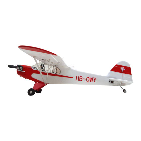
- Page 1 1400mm J-3 V3 Instruction Manual Bedienungsanleitung Manuel d’utilisation 操作手册 FLOAT RIGID STABLE Optional float Strong durable EPO Smooth flying performance...
- Page 2 WARNING WARNING: Read the ENTIRE instruction manual to become familiar with the features of the product before operating. Failure to operate the product correctly can result in damage to the product,personal property and cause serious injury. This is a sophisticated hobby product and NOT a toy. It must be operated with caution and common sense and failure to do so could result in injury or damage to the product or other property.
-
Page 3: Table Des Matières
Kit contents ····· ·························································3 others, are replicated in loving detail. Something worth noting is Model assembly ·······················································4 that FMS has made scale floats for the Cub as a response to Battery installation ············································· ····· ······ 9 ·· popular demand from the community. -
Page 4: Model Assembly
Model assembly Landing gear set installation PA2.6*15 1.With the fuselage bottom facing up, carefully Install the landing gear set to the fuselage with the included screws as shown. KA2.0*8 Main wing set installation 1.Have the screws go through the supporting bar and then secure on the base. 2.Lock up the fasteners of supporting bar on fuselage as shown. - Page 5 Model assembly 4.Secure the wings on the fuselage using the included screws as shown. HKM3.0*10 5.Lock up the fasteners of supporting bar on main wing as shown. Horizontal stabilizer installation KA2.0*8 1.Secure the horizontal stabilizer using included screws as shown.
- Page 6 Model assembly Vertical stabilizer installation KA2.0*12 1.Slide vertical stabilizer in the rear of the fuselage. 2.Secure the vertical stabilizer using included screws as shown. Linkage rod installation 1.Make sure the servos are in the neutral position. Install the linkage rod to elevator control horn as shown. Secure the linkage rod in place using the included screw as shown.
- Page 7 Model assembly Tail strut installation 1.Hook the tail struts to horizontal stabilizer and vertical stabilizer as shown. Antenna installation 1.Insert the antenna as shown. Propeller installation 1.Assemble the propeller as shown.
- Page 8 Model assembly Float set installation Screws 3*4 1.Assemble the float struts to the plastic holder as shown and secure the struts with screws. HKM3.0*10 2.Secure the float set onto the bottom of fuselage using the included plastic parts and screws as shown. Notice: The connectors on both side should be attached precisely and firmly.
-
Page 9: Battery Installation
Battery installation 1.Pull back on the latch, releasing the canopy. 2.Remove the canopy, revealing the battery compartment. 3.Apply hook and loop tape to the battery. 4.Install a fully charged battery into the battery compartment, with the battery cables facing aft. Note: The center of gravity can be adjusted by moving the battery forward or aft. - Page 10 Transmitter and model setup Before getting started, bind your receiver with your transmitter. Bank left Please refer to your transmitter manual for proper operation. CAUTION: To prevent personal injury, DO NOT install the propel- ler assembly onto the motor shaft while testing the control surfac- es.
-
Page 11: Clevis Installation
Clevis installation 1.Pull the tube from the clevis to the linkage. 2.Carefully spread the clevis, then insert the clevis pin into the desired hole in the control horn. 3.Move the tube to hold the clevis on the control horn. Control horn and servo arm settings More control throw Horns Arms... -
Page 12: Before Flying The Model
Before flying the model Flying course Find a suitable flying site Take off While applying power, slowly steer to keep the model straight. Find a flying site clear of buildings, trees, power lines and The model should accelerate quickly. As the model gains flight other obstructions. -
Page 13: Troubleshooting
Trouble shooting Problem Possible Cause Solution Aircraft will not respond to -Lower throttle stick and throttle trim to lowest settings. -ESC is not armed. the throttlebut responds to -Reverse throttle channel on transmitter. -Throttle channel is reversed. other controls. -Damaged spinner, propeller, -Replace damaged parts. - Page 15 Warnhinweise WARNUNG: Lesen Sie die GESAMTE Bedienungsanleitung, um sich vor der Inbetriebnahme mit den Funktionen des Produkts vertraut zu machen. Wenn das Produkt nicht ordnungsgemäß bedient wird, kann dies zu Schäden am Produkt oder persönlichem Eigentum führen und schwere Verletzungen verursachen. Dieses Produkt ist kein Spielzeug! Es muss mit Vorsicht und gesundem Menschenverstand betrieben werden.
-
Page 16: Einleitung
Sie wurde zur Aufklärung, zum Transport von • Vorbildgetreue Schwimmer optional erhältlich Vorräten und zur Evakuierung verwundeter Soldaten eingesetzt. Wie auch das Vorbild verfügt die J-3 Cub V3 von FMS über hervorragende Kurzstart und STOL (short takeoff and landing)- Inhaltsverzeichnis Eigenschaften. -
Page 17: Montage Des Modells
Montage des Modells Montage des Fahrwerks 1. Drehen Sie den Rumpf um und montieren Sie das Fahrwerk und die Abdeckung mit den beiliegenden Schrauben. PA2.6*15 KA2.0*8 Montage der Tragflächen 1. Befestigen Sie die langen Streben mit den entsprechenden Schrauben am Rumpf. 2. - Page 18 Montage des Modells 4. Befestigen Sie die Flächen wie abgebildet mit den beiliegenden Schrauben. HKM3.0*10 5.Verriegeln Sie die Streben wie abgebildet. Montage des Höhenleitwerks KA2.0*8 1. Montieren Sie das Höhenleitwerk wie abgebildet.
- Page 19 Montage des Modells Montage des Seitenleitwerks 1. Schieben Sie das Seitenleitwerk auf den Rumpf. KA2.0*12 2. Schrauben Sie das Seitenleitwerk wie abgebildet fest. Montage der Anlenkungen 1. Stellen Sie sicher, dass sich die Servos in neutraler Position befinden. Befestigen Sie die Kugelgabelköpfe und das Anlenkungsgestänge und sichern Sie es mit den entsprechenden Schrauben.
- Page 20 Montage des Modells Monatge der Heckstreben 1. Installieren Sie die Heckstreben wie abgebildet. Montage der Antenne 1. Installieren Sie die Antenne wie abgebildet. Montage des Propellers 1. Montieren Sie den Propeller wie abgebildet.
- Page 21 Montage des Modells Montage der Schwimmer Screws 3*4 1. Montieren Sie die Streben an den Kunststoffhaltern wie abgebildet mit den entsprechenden Schrauben. 2. Sichern Sie das Schwimmerset an der Unterseite des Rumpfes wie abgebildet mit den Kunststoffhaltern und den HKM3.0*10 Schrauben.
-
Page 22: Einsetzen Des Akkus
Einsetzen des Akkus 1. Nehmen Sie die Haube ab. 2. Befestigen Sie das Klettband am Akku 3. Schieben Sie den geladenen Akku mit den Kabeln nach hinten in bis ganz nach vorne im Akkufach. Hinweis: Der Schwerpunkt des Modells kann durch verschieben des Akkus verändert werden. - Page 23 Testen der Steuerfunktionen Bevor Sie mit diesem Schritt beginnen, binden Sie bitte der Rollen links Anleitung ihres Senders entsprechend den Empfänger mit dem Sender. ACHTUNG: Um mögliche Verletzungen zu vermeiden darf der Propeller bei dem Testen der Ruder NICHT auf der Welle montiert sein. Armieren Sie den Regler NICHT und schalten auch nicht den Sender ein bevor es in der Anleitung des Senders vorgeben wird.
-
Page 24: Montage Der Gabelköpfe
Montage der Gabelköpfe 1. Ziehen Sie den Ring vom Gabelkopf zum Gestänge. 2. Spreizen Sie den Gabelkopf vorsichtig und führen Sie den Gabelkopfstift in das gewünschte Loch im Ruderhorn ein. 3. Befestigen Sie den Ring um den Gabelkopf am Ruderhorn zu halten. -
Page 25: Vor Dem Erstflug
Vor dem Erstflug Fluggrundlagen Finden Sie einen geeigneten Flugplatz Starten Beschleunigen Sie das Modell vorsichtig und steuern Sie es Finden Sie einen Flugplatz frei von Gebäuden, Bäumen, langsam um es gerade zu halten. Erhöhen Sie die Stromleitungen und anderen Hindernissen. Bis Sie wissen, Beschleunigung und halten Sie eine gleichmäßige wie viel Fläche Sie zum fliegen brauchen, wählen Geschwindigkeit um das Modell in einem schönen Anstellwinkel... -
Page 26: Problemlösungen
Problemlösungen Problem Mögliche Ursache Lösung Modell nimmt kein Gas an, -Gasknüppel ist nicht ganz unten oder Trimmung zu hoch -Regler reagiert nicht andere Steuerungsbefehle -Gaskanal am Sender umkehren -Gaskanal ist umgekehrt funktionieren aber -Spinner, Propeller,Motor oder -Defekte Teile austauschen Ungewöhnliche Motorhalterung defekt -Lose Teile befestigen Propellergeräusche oder... - Page 28 ATTENTION ATTENTION : Lisez intégralement ce manuel d’utilisation pour vous familiariser avec les caractéristiques de ce produit avant de l’utiliser. Ne pas utiliser correctement ce produit peut entraîner des dommages au produit, aux biens matériels et causer des bless- ures graves. Il s’agit d’un produit de loisir technique, sophistiqué, et non d’un jouet.
-
Page 29: Introduction
Comme le modèle original, le nouveau J-3 1400mm de FMS offre d'excellentes capacités de décollage et atterrissage court Introduction ··························································· 27 et de superbes qualités de vol lent. FMS a mis le paquet pour Contenu du kit ······················································· 27 détailler au maximum cet avion, avec des éléments comme Montage du modèle... -
Page 30: Montage Du Modèle
Montage du modèle Montage du train principal 1. Le fuselage posé à l'envers, montez le train principal avec soin comme montré à l'aide des vis fournies. Pour les vis PA2.6*15 de fixation arrière, attendez l'étape suivante. KA2.0*8 Montage des ailes 1. - Page 31 Montage du modèle 4. Fixez les deux ailes sur le fuselage à l'aide des vis fournies,, comme montré. HKM3.0*10 5. Enclenchez les clips de fixation des renforts de mâts comme montré. Montage du stabilisateur horizontal KA2.0*8 1. Fixez le stabilisateur horizontal avec les vis fournies, comme montré.
- Page 32 Montage du modèle Montage de la dérive 1. Glissez la dérive à l'arrière du fuselage. KA2.0*12 2. Fixez la dérive avec les vis fournies comme montré. Montage des tringleries de commandes 1. Assurez-vous que le servo de profondeur est au neutre. Montez la commande de profondeur sur le palonnier du servo de profondeur comme montré.
- Page 33 Montage du modèle Montage des haubans de stab 1. Accrochez les haubans de stab entre le stabilisateur horizontal et la dérive, comme montré. Montage de l'antenne 1. Insérez l'antenne comme montré. Montage de l'hélice 1. Assemblez l'hélice comme montré.
- Page 34 Montage du modèle Montage du jeu de flotteurs Screws 3*4 1. Montez les mâts des flotteurs dans les supports en plastique et serrez les tiges avec les vis fournies. 2. Fixez l'ensemble des flotteurs sous le fuselage à l'aide des pièces en plastique et des vis fournies.
-
Page 35: Mise En Place De L'accu
Mise en place de l'accu 1. Deverrouillez la trappe d'accès et déposez-la pour dégager le logement de l'accu. 2. Collez du velcro adhésif sous votre pack d'accus. 3. Placez un pack d'accus chargés dans le logement, les câbles tournés vers l'avant. Note : Le centre de gravité... - Page 36 Réglage de l'émetteur et du modèle Avant de commencer, appairez votre récepteur à votre émetteur. Merci de vous reporter à la notice de votre ensemble radio pour effectuer cette opération correctement. ATTENTION : Pour éviter les blessures, NE MONTEZ PAS l'hélice sur l'axe du moteur pendant que vous contrôlez les gouvernes.
-
Page 37: Montage Des Chapes
Montage des chapes A et B. Sortez le tube verrou de chape vers la commande. C. Ouvrez la chape avec précaution, puis insérez le pion dans le trou désiré du guignol. D, E et F. Glissez le tube verrou sur la chape. Réglage des guignols et des palonniers de servos Plus de débattement Guignols... -
Page 38: Avant De Faire Voler Le Modèle
Avant de faire voler le modèle Pilotage du modèle Trouvez un site de vol adapté Décollage En mettant progressivement les gaz, maintenez l'axe avec la Trouvez un site de vol dégagé, à l'écart de bâtiments, d'arbres, direction, le modèle va accélérer rapidement.Quand le modèle de lignes électriques ou autres obstacles.Jusqu'à... -
Page 39: Dépannage
Dépannage Problème Cause possible Solution Le moteur de l'avion ne - Abaissez le manche de gaz et son trim tout en bas. - Le contrôleur n'est pas armé. répond pas, mais les - Inversez la voie des gaz sur l'émetteur. - La voie des gaz est inversée. - Page 41 警告 警告: 在组装、 调整及飞行前请务必认真阅读产品说明书以熟知产品的特性。 请严格按照说明书提示进行飞机的 组装、 调整及飞行。 如操作不当会造成产品本身损坏及其它财产损失, 甚至造成严重的人身伤害。 声明: 模型不是玩具, 具有一定的危险性, 操作者需要具备一定的飞行经验, 初学者请在专业人士指导下操作。 禁止十四岁以下儿童操作、 飞行。 安全须知 本产品飞行由无线电遥控器控制, 在飞行过程中可能会受到外 界强信号源干扰而导致失控, 甚至坠机。 因此, 在飞行 过程中务必始终与飞机保持一定的安全距离, 避免意外碰撞、 受伤。 ⸺请勿在发射器电池低电量的情况下操纵模型飞机。 ⸺请勿在公路、 人群、 高压线密集区、 机场附近及其它法律法规明确禁止飞行的场合飞行。 ⸺请勿在雷雨、 大风、 大雪或者其它恶劣气象环境下飞行。 ⸺请严格遵照产品指导说明及安全警告操作本产品及其相关配置 (例如充电器、 电池等) 。 ⸺请勿将相关化工类产品、 零部件、 电子部件等置于儿童可触及的范围。 ⸺请勿将电子件暴漏于潮湿的环境中,...
-
Page 42: 产品特点
派普J-3幼兽是一款美国轻型飞机,由派普飞机公司在1937-1947 ········ ·····························································39 年大量建造。J-3简单轻量的设计使其拥有卓越的低速操控性能和 产品组成 ·········· ·························································39 短距起降能力。在二战期间,J-3变更军用代号为L-4蚱蜢,被广 机体安装 ········ ·········· ·················································40 泛用于侦察、运输物资、火炮引导和撤退伤员。 电池安装 ·········· ········ ········································ ········44 FMS现在推出全新的1400mm级别J-3 Cub V3版本。FMS 1400m 接收机连接示意图 ········ ·········· ··························· ········45 m J-3 V3一如既往继承了真机优秀的低速操控性能和短距起降性 遥控器设置 能。它延续了V2版的组装、结构优势,继承了V2版高还原度的特 ·········· ·········· ································ ·······45 夹头安装方式 点。像真的发动机组件、起落架组件等,使之在外型上无限接近 ········ ········... -
Page 43: 机体安装
机体安装 起落架安装 1.如图所示, 保持机身底部朝上, 使用所附螺丝固定起落架。 PA2.6*15 KA2.0*8 主翼安装 1.如图所示, 将螺丝穿过主翼斜撑杆锁入机身底座。 2.将左右斜撑固定件卡进机身相应槽位。 PA2.6*15 3.如图所示, 把主翼对接管装入机身槽位, 安装左右两侧机翼。 注意: 确保插牢机翼和机身的对接插头。... - Page 44 机体安装 4.使用所附螺丝固定机翼。 HKM3.0*10 5.将左右斜撑固定件卡进主翼相应槽位。 平尾安装 KA2.0*8 1.如图所示, 使用所附螺丝固定平尾。...
- Page 45 机体安装 垂尾安装 KA2.0*12 1.如图所示, 将垂尾装入机身尾部滑槽。 2.使用所附螺丝固定垂尾。 连接钢丝安装 1.如图所示, 保持舵机在回中状态, 安装连接钢丝至平尾舵角, 使 用所附螺丝固定。 KA2.0*8 2.如图所示, 保持舵机在回中状态, 安装连接钢丝至垂尾舵角。 注意: 请参考46页舵角和舵机摇臂安装步骤。...
- Page 46 机体安装 1.如图所示, 安装尾撑至平尾和垂尾相应位置。 1.如图所示, 安装天线至机身。 1.如图所示, 依序安装螺旋桨和桨罩。...
- Page 47 机体安装 Screws 3*4 HKM3.0*10...
-
Page 48: 接收机连接示意图
接收机连接示意图 副翼 如图所示, 以Futaba遥控器为例, 将舵机信号线按照图示顺序插 平尾 入接收机通道, 将所有连接线整理整齐并固定在电池舱后部的凹 槽里, 随后固定好接收机。 请注意, 如产品配有LED, 则LED信号线 油门 可插入任何闲置通道。 垂尾 遥控器设置 警告: 为保证安全, 在遥控器参数设置及舵面调整过程中, 请务必拆下螺旋桨, 以免电机意外启动发生事故。 遥控器发射机开机 前, 确保油门杆在最低位置, 其它摇杆在中立位置。 开发射机并给接收机通电, 随后听到电调初始化音 (音符释义见后文 “电子 调速器说明书” ) 。 观察所有舵面是否回中, 如果没有回中, 尽量通过调整舵机摇臂角度、 连杆长度的方式来使舵面回中, 若调 整长度在安全范围内仍未回中, 则使用遥控器通道微调或者菜单中的 “SubTrim” 选项来使舵面归中。 如下图所示观察摇杆动作与 舵面动作的对应关系,... -
Page 49: 夹头安装方式
推荐舵面行程 大 小 升降舵 温馨提示: 首飞建议用小舵面行程 16mm up / dowm 12mm up / dowm 副翼舵 16mm up / dowm 12mm up / dowm 方向舵 18mm left / right 14mm left / right 夹头安装方式 1. 保证舵机为回中状态, 将连接杆夹头调整到合适位置。 2. 将 O 型圈移开, 打开夹头, 将夹头安装到舵角孔位。 3. -
Page 50: 重心调整
重心调整 通过移动电池在电池舱内的前后位置调整飞机的重心 ,使飞机保 55mm-65mm 持水平或稍微头重的状态。 首飞以后, 重心位置可以根据你自 己的飞行偏好再做更改。 1.如图所示, 推荐重心位置是机翼前缘往后 55-65mm 处 (安 装电池以后) 。 推荐把食指放在机翼下面的重心位置来帮助调 整重心。 2.在调整飞机重心的时候请确定飞机处于组装完毕待飞的状态。 飞行前准备 起飞前的检查 每次飞行前须做严格的地面检查, 可有效避免飞行事故的发生。 1. 检查全机螺丝是否安装到位、 舵角摇臂连接可靠。 机翼快拆装置已锁紧。 2. 安装电池, 并调整飞机重心到说明书推荐位置。 3. 动力电池、 遥控器发射机电池等已充满电, 处于可靠工作状态。 4. 发射机油门杆保持在最低位 (推荐使用带有油门锁定功能的遥控设备) , 打开发射机, 随后连接动力电池, 待电调初始化完成 后检查各个舵面是否回中,... -
Page 51: 故障检修指导
PRESC001 垂尾 9克塑胶正向舵机 (防水) FMSRK104 FMSSER9GPW 机头罩 充电器 FMSRK105 FMSCHR01 连接钢丝 浮筒组 FMSRK106 FMSFLT004 支撑杆 FMSRK107 前起落架组 FMSRK108 贴纸 FMSRK109 桨夹 FMSRK110 对接管 FMSRK111 螺丝组 FMSRK112 桨 FMSPROP021 电机轴 FMSDZ007 电机架 FMSDJ007 如需查找产品图片, 请登录FMS官方淘宝店https://fmsmodel.taobao.com。 如需查找电调说明书, 则在以上网址搜索栏中搜索 关键词 “电调” , 即可在任何一款电调产品页面查看。...