Table des Matières
Publicité
Les langues disponibles
Les langues disponibles
Liens rapides
Publicité
Chapitres
Table des Matières

Manuels Connexes pour ASCO Numatics Sentronic Plus 614 Série

Sommaire des Matières pour ASCO Numatics Sentronic Plus 614 Série
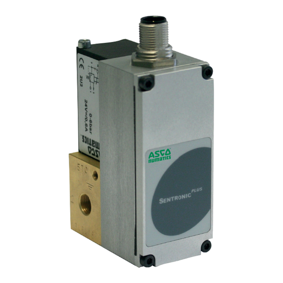
- Page 1 PLUS entronic Digital Pressure Regulator Series 614 Régulateur de pression numérique Series 614 Digitaler Druckregler Baureihe 614 Installation manual Manuel d'installation Installationshandbuch IM14229-R04 (3835192-B) GB FR DE...
-
Page 2: Table Des Matières
The information in this manual is subject to change without notice. In no event shall ASCO NUMATICS be liable for technical or editorial errors or omissions. Neither is any liability assumed for accidental or consequential damages arising out of or in connection with the supply or use of the information contained herein. -
Page 3: Description
INSTALLATION DESCRIPTION PLUS The S with integrated digital control loop combines the latest in pneumatics technology with intelli- entronic PLUS gent electronics. The S series allows precise control of pressure, flow, force, velocity and displace- entronic ment or angle positions. It supplements the S series. -
Page 4: Operating Elements
INSTALLATION OPERATING ELEMENTS Proportional solenoid coil Pressure supply Pressure outlet Exhaust Power supply, M12 connector or 7-pin DIN connector Ground connection M4 Mounting hole Serial communication RS232 (PC connection) LC display 2 pushbuttons OPERATING MODES Shut-off: If the setpoint falls below 0.5 %, the coil current is switched off and the valve is fully exhausted. Overtemperature: If the temperature of the internal control electronics exceeds 100°C, the operating mode is switched to AUTOSAFE. -
Page 5: Electrical Connection
INSTALLATION ELECTRICAL CONNECTION 5-pin M12 female connector Valve Control M12 connector +24V supply voltage Supply voltage GND 250 Ohm at current setpoint Setpoint 0-10V (or 0-20 / 4-20mA) Setpoint GND (only for 6-wire cable) Analog output: Feedback Only at current output: 0-10V max. - Page 6 INSTALLATION 7-pin DIN connector Connector on View on solder side electronic card of female connector Supply voltage +24V Supply voltage GND Setpoint (or 0-20 mA or 4-20 mA) Setpoint GND Not used Outlet pressure feedback (Output) 0-10V (or 0-20mA or 4-20mA) PRESSURE SWITCH OUTPUT NPN if setpoint + 30V max.
-
Page 7: Analog Setpoint - Outlet Pressure
INSTALLATION ANALOG SETPOINT - OUTLET PRESSURE Setpoint offset The pressure setpoint zero can be changed via the DaS software. Switch to "Custom" in the "Setpoint setting" section. The zero range is max. -50 ... +100 %. Max. Max. Max. outlet pressure outlet pressure inlet pressure (bar) -
Page 8: Pneumatic Connection
INSTALLATION PNEUMATIC CONNECTION The air flow is from port 1 to port 2. Exhaust Pressure outlet Pressure supply Inch screw connections (pipe threads) must be used. Each screw connections must be lined with a fitting synthetic sealing disc. Do not use Teflon sealing tape or hemp as they may get inside the valve and damage it. Use an appropriate silencer at port (3). -
Page 9: Specifications
INSTALLATION SPECIFICATIONS Flow Nominal Supply diameter Max. power Max. current Insulation Degree of at 6 bar voltage Electrical connections (mA) class protection (l/min (stabilised) (mm) ANR) 0,18 5-pin female M12 connector 1000 0,60 +/-10% 24 V= IP 65 1400 1,20 1400 7-pin female DIN connector 1800... -
Page 10: Warning Notes
Before using these products with fluids other than those specified, for non-industrial applications, life-support systems, or other applications not within published specifications, consult ASCO Numatics. Through misuse, age, or malfunction, components used in fluid power systems can fail in various modes. -
Page 11: Dimensions And Weight
INSTALLATION DIMENSIONS (mm), WEIGHT (kg) PLUS - Digital electronic pressure regulator valve with M12 connection entronic G 1/8 Weight: 0,550 kg PE(4-8 deep) 2xM4-10 deep G 1/4 Weight: 0,850 kg PE(4-8 deep) G 1/2 Weight: 1,650 kg PE(4-8 deep) IM14229-11... - Page 12 INSTALLATION DIMENSIONS (mm), WEIGHT (kg) PLUS - Digital electronic pressure regulator valve with M12 connection entronic Weight: 3,400 kg PE(4-8 deep) IM14229-12...
- Page 13 INSTALLATION DIMENSIONS (mm), WEIGHT (kg) PLUS - Digital electronic pressure regulator valve with 7-pin DIN connector entronic G 1/8 Weight: 0,550 kg 34.8 G 1/4 Weight: 0,850 kg 34.8 IM14229-13...
- Page 14 INSTALLATION DIMENSIONS (mm), WEIGHT (kg) PLUS - Digital electronic pressure regulator valve with 7-pin DIN connector entronic G 1/2 Weight: 1,650 kg 34.8 57.5 Weight: 3,400 kg 34.8 100.7 IM14229-14...
- Page 15 INSTALLATION DIMENSIONS (mm), WEIGHT (kg) PLUS - with external pressure supply and M12 connection entronic G 1/8 Weight: 0,700 kg PE(4-8 deep) G 1/4 Weight: 1,000 kg PE(4-8 deep) 2x Ø4,3 G 1/2 Weight: 1,800 kg PE(4-8 deep) 2x Ø 5 22,5 57,5 IM14229-15...
- Page 16 INSTALLATION DIMENSIONS (mm), WEIGHT (kg) PLUS - with external pressure supply and M12 connection entronic Weight: 3,550 kg PE(4-8 deep) 2x Ø7 durchgehend IM14229-16...
- Page 17 INSTALLATION DIMENSIONS (mm), WEIGHT (kg) PLUS - with external pressure supply and 7-pin DIN connector entronic G 1/8 Weight: 0,700 kg 34.8 G 1/4 Weight: 1,000 kg 34.8 86.063 IM14229-17...
- Page 18 INSTALLATION DIMENSIONS (mm), WEIGHT (kg) PLUS - with external pressure supply and 7-pin DIN connector entronic G 1/2 Weight: 1,800 kg 34.8 57.5 Weight: 3,550 kg 34.8 118.7 IM14229-18...
- Page 19 Régulateur de pression numérique PLUS entronic Série 614 Manuel d'installation IM14229-FR/R04 (3835192-B)
- Page 20 NOTES Les informations contenues dans le présent manuel sont susceptibles d’être modifiées sans préavis. ASCO NUMATICS ne peut être tenu responsable des omissions techniques ou rédactionnelles, ni des dommages accidentels ou consécutifs à la fourniture ou l’utilisation du présent document.
-
Page 21: Description
INSTALLATION DESCRIPTION PLUS à boucle de régulation interne numérique associe une technologie pneumatique innovante et une entronic électronique integrée. Cette série de distributeurs permet de réguler avec précision les valeurs de pression, débit, PLUS force, vitesse, et de positionnement linéaire ou angulaire. La série de vannes S vient compléter la entronic série S... -
Page 22: Composants De Fonctionnement
INSTALLATION COMPOSANTS DE FONCTIONNEMENT Bobine proportionnelle Alimentation en pression Utilisation Echappement Alimentation électrique, connecteur M12 ou connecteur DIN à 7 broches Connexion de mise `da la terre, M4 Orifice de montage Communication série RS232 (liaison PC) Affichage LC 2 Boutons-poussoirs MODES DE FONCTIONNEMENT Shut off (fermeture) : Si la pression de sortie devient inférieure à... -
Page 23: Raccordement Électrique
INSTALLATION RACCORDEMENT ELECTRIQUE Connecteur femelle M12 5 broches Vanne Contrôle Connecteur M12 Alimentation +24V Masse d’alimentation GND 250 Ohm à la consigne courant Consigne 0-10V (ou 0-20 / 4-20mA) Masse consigne GND (seul pour câble à 6 fils) Sortie analogique : Retour Seul pour sortie cour- 0-10V... - Page 24 INSTALLATION Connecteur DIN 7 broches Connecteur sur Vu coté soudure carte électronique +24V Alimentation en tension Masse d'alimentation GND Consigne (ou 0-20 mA ou 4-20 mA) Masse consigne GND Non utilisée Retour de la pression de sortie (Sortie) 0-10V (ou 0-20mA ou 4-20mA) SORTIE PRESSOSTAT NPN si consigne + 30V maxi...
-
Page 25: Consigne Analogique - Pression De Sortie
INSTALLATION CONSIGNE ANALOGIQUE - PRESSION DE SORTIE Décalage du zéro Le réglage du point zéro de consigne peut être effectué par le programme DaS. Pour ce faire, sélectionner "Personnalisé" sous "Réglage consigne". La plage du zéro est de -50 ... +100 % au maximum. Pression de Pression de Pression... -
Page 26: Raccordement Pneumatique
INSTALLATION RACCORDEMENT PNEUMATIQUE Le sens de circulation de l'air est de 1 vers 2. Echappement 3 Utilisation 2 Alimentation pression 1 Les taraudages gaz sont à utiliser. Chaque connexion vissée doit être montée avec un joint d’étanchéité synthétique adapté. Ne pas utiliser de ruban d’étanchéité en Teflon ou de chanvre car ils pourraient pénétrer à l’intérieur de la vanne et l’endommager. -
Page 27: Sélection Du Matériel
INSTALLATION SÉLECTION DU MATÉRIEL débit diamètre tension puissance maxi courant maxi classe degré de à 6 bar nominal DN raccordement électrique coeff. K (stabilisée) (mA) d'isolation protection (l/min (mm) ANR) 0,18 connecteur femelle M12 1000 0,60 à 5 broches +/-10% 24 V= IP 65 ou connecteur femelle DIN... -
Page 28: Consignes De Securite
Avant d'utiliser les produits avec des fluides autres que ceux spécifiés, pour des applications non-industrielles, dans des systèmes de support vie ou d'autres systèmes non spécifiés, veuillez consulter ASCO Numatics. L'utilisation abusive, l'usure ou le dysfonctionnement peuvent entraîner de différents modes de défaillance des compo- sants utilisés dans les systèmes hydrauliques et pneumatiques. - Page 29 Digitaler Druckregler PLUS entronic Baureihe 614 Installationshandbuch IM14229-DE/R04 (3835192-B)
- Page 30 DIE IN DIESEM HANDBUCH ENTHALTENEN ANGABEN KÖNNEN OHNE VORHERIGE ANKÜNDIGUNG GEÄNDERT WERDEN. ASCO NUMATICS übernimmt keinerlei Haftung für technische oder redaktionelle Fehler oder Ungenauigkeiten oder für versehentlich entstehende Schäden oder Folgeschäden, die durch die Bereitstellung dieses Handbuchs oder aus der Anwendung desselben entstehen.
-
Page 31: Beschreibung
INSTALLATION BESCHREIBUNG PLUS mit integriertem digitalem Regelkreis verbindet neueste Pneumatik-Technologie mit intelligenter entronic Elektronik. Diese Baureihe ermöglicht die exakte Regelung von Druck, Durchfluss, Kraft, Geschwindigkeit und PLUS Weg oder Winkelpositionen. Die Baureihe S ist eine Ergänzung zur S -Baureihe. entronic entronic PLUS ist in 14 Standarddruckbereichen von 100 mbar bis 50 bar erhältlich. -
Page 32: Bedienelemente
INSTALLATION BEDIENELEMENTE Proportionalmagnet Druckversorgung Druckausgang Entlüftung Elektrische Versorgung, M12-Stecker oder 7-po- liger DIN-Stecker Anschluss für Schutzerde, M4 Befestigung Serielle Kommunikation RS232 (PC-Anschluss) LC-Display 2 Tasten BETRIEBSZUSTÄNDE Shutoff: Wird der Sollwert kleiner 0,5 %, so wird der Proportionalmagnet stromlos geschaltet und das Ventil entlüftet vollständig. -
Page 33: Elektrischer Anschluss
INSTALLATION ELEKTRISCHER ANSCHLUSS 1. Das Ventil darf nur mit einer Versorgungsspannung von 24VDC ±10% und einer maximalen Welligkeit von 10% betrie- ben werden. (Eine Einspeisung über Diodenbrücke ist nicht gestattet). Überspannungen und Welligkeiten außerhalb dieser Toleranzen können zu einer Beschädigung der Elektronik führen. 2. - Page 34 INSTALLATION 7poliger Steckverbinder Steckverbinder Ansicht auf Lötseite auf der Elektronikkarte der Kabeldose Spannungsversorgung +24V Versorgungsmasse Sollwert (oder 0-20 mA oder 4-20 mA) Sollwertmasse Nicht belegt Istwert: Ausgangsdruck (Ausgang) 0-10V (oder 0-20mA oder 4-20mA) DRUCKSCHALTERAUSGANG NPN bei Erreichen + 30V max. des Sollwerts Ist = Soll I = 500 mA max.
-
Page 35: Analoger Sollwert - Ausgangsdruck
INSTALLATION ANALOGER SOLLWERT - AUSGANGSDRUCK Sollwert-Nullpunkt Der Druck-Nullpunkt des Sollwerts kann über die DaS-Software verändert werden. Hierzu im Abschnitt "Sollwerteinstel- lung" auf "Kunde" umschalten. Der Einstellbereich für den Nullpunkt ist maximal -50 ... +100 %. Max. Max. Max. Ausgangsdruck Ausgangsdruck Eingangsdruck (bar) (bar) -
Page 36: Pneumatischer Anschluss
INSTALLATION PNEUMATISCHER ANSCHLUSS Die pneumatische Durchflussrichtung ist von Anschluss 1 nach 2. Entlüftung 3 Druckausgang 2 Druckversorgung 1 Es sind zöllige Verschraubungen (Rohrgewinde) zu verwenden. Jede Verschraubung ist mit einem passenden Kunststoffdichtring zu unterlegen. Teflondichtband und Hanf dürfen nicht verwendet werden, da sie in das Innere des Ventils gelangen können. An der Entlüftung (3) ist ein passender Schalldämpfer zu verwenden. -
Page 37: Kennwerte
INSTALLATION KENNWERTE Ø Leistungs- Strom- Durchfluss Versorgungs- Nennweite aufnahme aufnahme Isolations- spannung Schutzart Elektrischer Anschluss -Wert bei 6 bar max. max. klasse (geregelt) (Nl/min) (mm) (mA) 0,18 5-polige Leitungsdose M12 1000 0,60 +/-10% 24 V= IP 65 oder 1400 1,20 1400 7-polige DIN-Leitungsdose 1800... -
Page 38: Sicherheitshinweise
Vor dem Einsatz der Produkte mit Flüssigkeiten sowie bei nicht industriellen Anwendungen, in lebenserhaltenden- oder anderen Systemen, die nicht in den veröffentlichten Anleitungsunterlagen enthalten sind, wenden Sie sich bitte direkt an ASCO Numatics. Durch Missbrauch, Verschleiß oder Störungen können in Hydrosystemen verwendete Komponenten auf verschiedene Arten versagen. - Page 40 INSTALLATION ASCO Numatics GmbH Otto-Hahn-Straße 7-11 75248 Ölbronn-Dürrn Germany Tel: +49 7237 996-0 Email: asconumatics-de@emerson.com www.asconumatics.eu IM14229-40...