Table des Matières
Publicité
Les langues disponibles
Les langues disponibles
Liens rapides
Montage- und Bedienungsanleitung für
Notice de montage et d'utilisation du
No. de commande 9918A
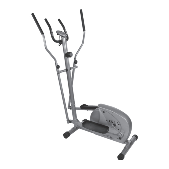
Heimsport-Trainingsgerät
CS 1.1
D
Bestell-Nr. 9918A
F
RU
Инструкция по монтажу и эксплуатации
№ заказа 9918A
GB
Assembly and exercise instructions for
Order No. 9918A
NL
Montage- en bedieningshandleiding voor
Bestellnummer 9918A
1
Publicité
Chapitres
Table des Matières

Manuels Connexes pour Christopeit Sport CS 1.1


Sommaire des Matières pour Christopeit Sport CS 1.1
- Page 1 Heimsport-Trainingsgerät CS 1.1 Montage- und Bedienungsanleitung für Assembly and exercise instructions for Bestell-Nr. 9918A Order No. 9918A Notice de montage et d’utilisation du Montage- en bedieningshandleiding voor No. de commande 9918A Bestellnummer 9918A Инструкция по монтажу и эксплуатации № заказа 9918A...
-
Page 2: Table Des Matières
Inhaltsübersicht Contents Page 1. Wichtige Empfehlungen und Sicherheitshinweise Seite 2. Einzelteileübersicht Seite 3. Stückliste Seite 4 - 5 4. Montageanleitung mit Explosionsdarstellungen Seite 6 - 8 5. Computeranleitung Seite Sommaire Page 6. Trainingsanleitung Seite 10 Sehr geehrte Kundin, sehr geehrter Kunde Wir gratulieren Ihnen zum Kauf dieses Heims port-Trai nings ge rä... -
Page 4: Stückliste - Ersatzteilliste
Nach Öffnen der Verpackung bitte kontrollieren, ob alle Teile ent- Stückliste - Ersatzteilliste spre chend der nachfolgenden Stückliste vor han den sind. Ist dies CS 1.1 Best.-Nr. 9918A der Fall, können Sie mit dem Zu sam men bau beginnen. Technische Daten: Stand: 01. - Page 5 Stückliste - Ersatzteilliste CS 1.1 Best.-Nr. 9918A Abbildungs- Bezeichnung Abmessung Menge Montiert an ET-Nummer Stück Abbildungs Nr. Distanzstück 36-9918-23-BT Widerstandsregulierung 36-9918-24-BT Hutmutter 39-9900-VC Fuß vorne 33-9918-19-SI Fußkappe mit Transportrolleneinheit 36-9918-25-BT Schlossschraube 8x75 51+87 39-10019-CR Sechskantschraube M10x85 39-10122 Sensorkabel 36-9918-26-BT Grundrahmen...
-
Page 6: Montageanleitung Mit Explosionsdarstellungen
Montageanleitung Bevor Sie mit der Montage beginnen, unbedingt unsere Empfehlungen und Sicherheitshinweise beachten! Schritt 1: Montage des Vorderen Fußrohr (51) und des Hinteren Fußrohr (87) am Grundrahmen (56) mittels der Schloßschrauben (53), der Unterleg- scheiben 8//19 (18), der Federringen (10) und der Hutmuttern M8 (50). 1. - Page 7 Schritt 4: Montage der rechten Fußschale (88) an der rechten Fußschalenauf- nahme (89) und der linken Fußschale (29) an der linken Fußschalen- aufnahme (32) mittels der Schrauben (28), der Unterlegscheiben (33) und der Mutter (34). 1. Die rechte Fußschale (88) auf die Fußschalenaufnahme (89) aufste- cken.
- Page 8 Schritt 7: Montage des Haltegriff (3) am Stützrohr (46) mittels der Flügelschrau- be (12). 1. Führen Sie den Haltegriff (3) zur geöffneten Aufnahme am Stützrohr (46) und schließen Sie diese über den Haltegriff (3). 2. Auf die Flügelschraube (12) das Distanzstück (11) und die Abdeck- kappe (95) aufstecken und den Haltegriff (3) am Stützrohr (46) in ge- wünschter Position fest montieren.
-
Page 9: Computeranleitung
Computeranleitung für 9918A Der mitgelieferte Computer bietet den größten Trainingskomfort. Jeder „L“= Löschen: trainingsrelevante Wert wird in dem Sichtfenster angezeigt. Durch ein kurzes Drücken dieser Taste kann der durch die „F“-Taste aus- gewählte Wert auf Null gesetzt werden. Vom Trainingsbeginn an werden die benötigte Zeit, die aktuelle Ge schwin - Durch ein längeres Drücken der Taste (ca. -
Page 10: Trainingsanleitung
Trainingsanleitung Um spürbare körperliche und gesundheitliche Verbesserungen zu er rei chen, müssen für die Bestimmung des erforderlichen Trai nings auf wan des die fol- gen den Faktoren beachtet werden: 1. Intensität: Die Stufe der körperlichen Belastung beim Training muß den Punkt der nor ma len Belastung überschreiten, ohne dabei den Punkt der Atem lo sig keit und /oder der Erschöpfung zu er rei chen. -
Page 11: Important Recommendations And Safety Instructions
Contents 1. Summary of Parts Page 2. Important Recommendations and Safety Information Page 11 3. Parts List Page 12 - 13 4. Assembly Instructions With Exploded Diagrams Page 14 - 16 5. Computer instructions Page 17 6. Training Instructions Page 18 Dear customer, We congratulate you on your purchase of this home training sports unit and hope that we will have a great deal of pleasure with it. -
Page 12: Parts List
Please check after opening the packing that all the parts shown in Parts List – Spare Parts List the following parts lists are there. Once you are sure that this is the CS 1.1 Order No. 9918A case, you can start assembly. Technical data: Issue: 01. - Page 13 Parts List – Spare Parts List CS 1.1 Order No. 9918A Illustration Designation Dimensions Quantity Attached to ET number illustration No. swing bar gap sleeve 36-9918-23-BT 8-stage tension control 36-9918-24-BT 39-9900-VC front stabilizer 33-9918-19-SI front transportation wheel 36-9918-25-BT carriage screw...
-
Page 14: Assembly Instructions With Exploded Diagrams
Assembly Instruction Before beginning assembly, be sure to observe our recommenda- tions and safety instructions. Step 1: Install of the front footbar (51) and the rear footbar (87) on the main frame (56) with the carriage bolts (53), the washers 8//19 (18), spring washer (10) and the cap nuts M8 (50). - Page 15 Step 4: Installation of the right footrest (88) on the right footrest holder (89) and the left footrest (29) on the left footrest holder (32) with the bolts (28), the washers (33) and the nuts (34). 1. Push the right footrest (88) onto the footrest holder (89). Adjust the holes in the parts so that they are aligned.
- Page 16 Step 7: Attach the hand grip bar (3) at support (46) wit handle bar screw (12). 1. Place the hand grip bar (3) against the open holder of support (46) and close the clamp. 2. Push a spacer (11) and the handlebar cover (95) onto the handlebar screw (12) and tighten the handgrip bar (3) at support (46) into desire position fi...
-
Page 17: Computer Instructions
Computer instructions for 9918A The supplied computer allows the most convenient training. Every value relevant to training is displayed in the window. From the beginning of the training session, the required time, the current speed, the approximate calory consumption, the travelled distance, the travelled distance of all training sessions and the current pulse rate are displayed. -
Page 18: Training Instructions
Training instructions You must consider the following factors in determining the amount of training effort required in order to attain tangible physical and health benefi ts: 1. Intensity: The level of physical exertion in training must exceed the level of normal exertion without reaching the point of breathlessness and / or exhaustion. -
Page 19: Recommandations Importantes Et Consignes De Sécurité
Sommaire 1. Aperçu des pièces Page 2. Recommandations importantes et règles de sécurité Page 3. Nomenclature Page 20 - 21 4. Notice de montage avec écorchés Page 22 - 24 5. Manuel d’utilisation du calculateur électronique Page 6. Recommandations pour l’entraînement Page Chère cliente, cher client, Nous vous félicitons pour l’achat de ce cycle d’entraînement intérieur et... -
Page 20: Liste Des Pièces- Liste Des Pièces De Rechange Cs 1.1 N° De Commande 9918A
Liste des pièces- Liste des pièces de rechange Après avoir ouvert l’emballage, veuillez contrôler s’il y a toutes les pièces conformément à la liste suivante. Si c’est le cas, vous pouvez CS 1.1 N° de commande 9918A commencer l’assemblage. Caractéristiques techniques : Version du : 01/ 11/ 2006 Si une pièce n’est pas correcte, s’il manque une pièce ou si vous... - Page 21 Liste des pièces- Liste des pièces de rechange CS 1.1 N° de commande 9918A Schéma Désignation Dimensions Quantité Monté sur Numéro ET n° en mm Unités schéma n° Réglage de la résistance 36-9918-24-BT Ecrou à chapeau 39-9900-VC Tube du pied avant 33-9918-19-SI Chapeaux fi...
- Page 22 Instructions de montage Il est strictement conseillé d’observer nos recommandations et consi- gnes de sécurité avant de commencer le montage ! Etape n° 1: Montage du tube du pied avant (51) et du tube du pied arrière (87) sur le cadre de base (56) à l’aide des boulons bruts à tête bombée et collet carré...
- Page 23 Etape n° 4: Montage de la coque de la pédale droite (88) sur le logement de la co- que de la pédale droite (89) et de la coque de la pédale gauche (29) sur le logement de la coque de la pédale gauche (32) à l’aide des boulons (28), des rondelles (33) et des Écrou (34).
- Page 24 Etape n° 7: Montage du poignée de maintien (3) sur le tube de support (46). 1. Dirigez la poignée de maintien (3) vers le logement ouvert du guidon, au niveau du tube support (46) et fermez-le au-dessus du poignée de maintien (3).
- Page 25 Mode d’emploi de l‘ordinateur 9918A L’ordinateur livré vous offre le plus grand confort d‘entraînement. Chaque chages, à l’exception des valeurs affi chées dans „KM-TOTAL“, appuyer plus valeur importante pour l’entraînement est affi chée dans une fenêtre. longuement sur cette touche (pendant environ 3 secondes). Le temps nécessaire, la vitesse actuelle, la consommation de calories ap- 2.
-
Page 26: Recommandations Pour L'entraînement
Recommandations pour l’entraînement Les facteurs ci-après doivent être pris en compte pour la détermination de l’entraînement indispensable afi n d’améliorer concrètement son physique et sa santé: 1. Intensité: L’entraînement n’aura d’effets positifs que si les efforts déployés dépassent ceux de la vie quotidienne, mais sans être hors d’haleine et/ou se sentir épui- sé. -
Page 27: Belangrijke Aanbevelingen En Veiligheidsinstructies
Inhoudsopgave 1. Overzicht van de losse delen pagina 2. Belangrijke aanbevelingen en veiligheidsinstructies pagina 27 3. Stuklijst pagina 28 - 29 4. Montagehandleiding met explosietekeningen pagina 30 - 32 5. Handleiding bij de computer pagina 33 6. Trainingshandleiding pagina 34 Geachte klant Wij willen u van harte gelukwensen met de aanschaf van uw hometrainer en hopen dat u hier veel plezier aan zult beleven. - Page 28 Controleer na het openen van de verpakking a.u.b. aan de hand van de onderstaande stuklijst of alle onderdelen aanwezig zijn. Wan ne er CS 1.1 best.nr. 9918A dit het geval is, kunt u met de montage beginnen. Technische specifi catie: Stand: 01.
- Page 29 Stuklijst - reserveonderdelenlijst CS 1.1 best.nr. 9918A Afbeeldings- Beschrijving Afmetingen Aantal Gemonteerd aan ET-nummer stuks afbeeldingsnr. Afstandsstuk 36-9918-23-BT Weerstandsinstelling 36-9918-24-BT Dopmoer 39-9900-VC Voetbuis voor 33-9918-19-SI Eindkappen met transportrol 36-9918-25-BT Slotschroef M8x75 51+87 39-10019-CR Zeskantschroef M10x85 39-10122 Sensorkabel 36-9918-26-BT Basisframe 33-9918-20-SI...
- Page 30 Montagehandleiding Voordat u met de montage begint, absoluut onze adviezen en veiligheidsvoorschriften in acht nemen! Stap 1: Montage van de voorste voetbuis (51) en de achterste voetbuis (87) op het frame (56) door middel van de sluitschroeven (53), de onderlegplaatjes 8//20 (19), de veeringen (10) en de dopmoeren M8 (50).
- Page 31 Stap 4: Montage van de rechter voetschaal (88) aan de rechter voetschaalbe- vestiging (89) en de linker voetschaal (29) aan de linker voetschaalbe- vestiging (32) met behulp van de zeskantschroef (28), de onderlegplatje (33) en de moer (34). 1. De rechter voetschaal (88) op de bevestiging (89) steken. De openingen in de delen zo uitlijnen dat ze precies boven elkaar liggen.
- Page 32 Stap 7: Montage van het handgreep (3) an het steunbus (46). 1. Voer het handgreep (3) door de geopende handgreephouder op de steunbuis (46) en sluit u deze over het handgreep (3). 2. Plaatst u een afstandstuk (11) en de afdekkappen (95) op de vleugel- schroef (12) en hiermee bevestigd u het handgreep (3) in de gewenste positie op stuurbuis (46).
- Page 33 Computerhandleiding voor 9918A De bijgeleverde computer zorgt voor een uitstekend trainingscomfort. Elke trainingsrelevante waarde wordt in het venster weergegeven. Vanaf het begin van de training worden de benodigde tijd, de actuele snel- heid, het verbruikte aantal calorieën, de afgelegde afstand, de afgelegde afstand van alle trainingunits en de actuele hartslag weergegeven.
- Page 34 Trainingshandleiding De onderstaande factoren moeten in acht worden genomen bij het bepalen van de benodigde training voor het bereiken van een merkbare verbetering van uw fi guur en gezondheid: 1. Intensiteit: De mate van lichamelijke belasting bij de training moet de normale belasting overschrijden, zonder dat u daarbij buiten adem en/of uitgeput raakt.
-
Page 35: Обзор Содержания
Обзор содержания Важные рекомендации и указания по безопасности ctp. 2. Обзор отдельных деталей стр. 3. Спецификация стр. 36 - 37 4. Руководство по сборке с отдельными иллюстрациями стр. 38 - 40 5. Руководство по использованию компьютера стр. 6. Руководство по тренировкам стр. - Page 36 Сняв упаковку, проверьте по списку, все ли детали на месте. Спецификация - Список запасных частей Если все в порядке, то можно начинать сборку. Если какой- CS 1.1 № заказа 9918A нибудь агрегат не в порядке или отсутствует, обращайтесь к Технические характеристики...
- Page 37 Спецификация - Список запасных частей CS 1.1 № заказа 9918A № Наименование Размеры в мм Кол-во Монтируется на № ЕТ-№ картинки штук Колпачковая гайка 39-9900-VC Передняя ножная труба 33-9918-19-SI Концевой колпачок с транспортировочным роликом 36-9918-25-BT Замковый болт с грибовидной головкой...
-
Page 38: Руководство По Монтажу
Руководство по монтажу Прежде чем Вы начнете производить монтаж, следует непременно обратить внимание на наши рекомендации и указания по технике безопасности Шаг 1: Монтаж передней ножной трубы (51) и задней ножной трубы (87) на основную раму (56) с помощью замкового болта с грибовидной головкой... - Page 39 Шаг 4: Монтаж фиксатора стопы справа (88) на ножной рычаг справа (89) и фиксатора стопы слева (29) на ножной рычаг слева (32) с помощью болтов (28), подкладных шайб (33) и гаек (34). Вставьте фиксатор стопы справа (88) на ножной рычаг (89) таким образом, чтобы...
- Page 40 Шаг 7: Монтаж поручня (3) на опорную трубу (46) с помощью болта для крепления руля (12). Подведите поручень (3) к открытому креплению руля на опорной трубе (46) и закройте его над рулем (3). 2. Наденьте на болт для крепления руля (12) промежуточное тело (11) и...
- Page 41 Руководство по использованию компьютера на тренажере серии 9918A Входящий в комплект оборудования снаряда компьютер обеспечит ФУНКЦИЯ КЛАВИШ: Вам максимальный комфорт во время тренировки. Любой важный для 1. Клавиша „F“: тренировочного процесса показатель отражается на дисплее. Коротким однократным нажатием клавиши можно переходить от одной Перед...
- Page 42 ИНСТРУКЦИЯ ПО ТРЕНИРОВКЕ Вы должны учитывать следующие факторы, чтобы определить верные параметры тренировок для достижения ощутимых физических результатов и пользы для здоровья. Интенсивность Уровень физических нагрузок при тренировках должен превышать уровень нормальных физических нагрузок, но вы не должны задыхаться и сильно переутомляться. Удобной мерой эффективности тренировки...
- Page 44 Service Bei Reklamationen, notwendigen Ersatzteilbestellungen oder © by Top-Sports Gilles GmbH Reparaturen wenden Sie sich bitte an unsere Service Abteilung. D-42551 Velbert (Germany) Service: Top-Sports Gilles GmbH Tel.: +49 (0)2051/6067-0 Friedrichstrasse 55 info@christopeit-sport.com Fax: +49 (0)2051/6067-44 D - 42551 Velbert http://www.christopeit-sport.com...