Table des Matières

Publicité

Les langues disponibles
  • FR

Les langues disponibles

Liens rapides

FORNO PER PIZZA - PIZZA-OVEN - FOUR POUR PIZZA -
PIZZA-OFEN - HORNO PARA PIZZA
SUPERTOP
Mod.
SUPERTOP VARIO
Mod.
MANUALE D'USO
USER MANUAL
MODE D'EMPLOI
BEDIENUNGSANLEITUNG
MANUAL DE USO

Publicité

Table des Matières
loading

Sommaire des Matières pour OEM SUPERTOP

  • Page 1 FORNO PER PIZZA - PIZZA-OVEN - FOUR POUR PIZZA - PIZZA-OFEN - HORNO PARA PIZZA SUPERTOP Mod. SUPERTOP VARIO Mod. MANUALE D'USO USER MANUAL MODE D'EMPLOI BEDIENUNGSANLEITUNG MANUAL DE USO...
  • Page 2 Serial number - Numéro d' immatriculation - Kenn-Nummer - Número de matrícula Data di consegna......................Delivery date - Date di livraison - Lieferdatum - Fecha de entrega Realizzato per OEM ALI Group S.r.l. a Socio Unico da DUESSE Service - Samarate (VA) - www.duesse.it...
  • Page 3: Dichiarazione Ce Di Conformita

    Dichiara che il modello - It is hereby declared that model Déclare que le modèle - erklärt, daß die Maschine Modell SUPERTOP VARIO 440 - 640S - 640L - 940 FORNI ELETTRICI - ELECTRIC OVEN è conforme alle disposizioni legislative che traspongono le direttive e successivi emendamenti: SUPERTOP 435 –...
  • Page 4 Frontespizio - Frontispiece - Frontispiece Titelseite - Frontespizio INDICE GENERALE GENERAL INDEX - INDEX GENERAL ALLGEMEINES INHALTSVERZEICHNIS - ÍNDICE GENERAL - Italiano ........ Pag.IT - 1 (Istruzioni originali) English ......Pag.EN - 1 (Translation of original instructions) Français ......Pag.FR - 1 (Traduction des instructions d’origine) Deutsch ......
  • Page 5: Table Des Matières

    SUPERTOP - SUPERTOP VARIO Norme ed avvertenze generali ITALIANO 5.5 - PROGRAMMAZIONE PARAMETRI DI COTTURA ..27 CAPITOLO ............5.6 - ILLUMINAZIONE CAMERA ......... 28 5.7 - MENU’ UTENTE ............29 Capitolo per il tecnico e l'operatore 5.8 - TIMER AUTOACCENSIONE ........30 1.1 -...
  • Page 6 SUPERTOP - SUPERTOP VARIO Norme ed avvertenze generali IT - 2...
  • Page 7: Avvertenze Generali

    SUPERTOP - SUPERTOP VARIO Norme ed avvertenze generali Capitolo 1 1.1 - AVVERTENZE GENERALI - L’impianto di alimentazione elettrica, dell’ac- - Prima di procedere alla messa in funzione quirente, deve essere provvisto di un sistema dell'apparecchio l’operatore dovrà aver let- di sgancio automatico a monte dell’interrut-...
  • Page 8 SUPERTOP - SUPERTOP VARIO Norme ed avvertenze generali - Il pavimento nei pressi del forno può essere - E’ fatto assoluto divieto a chiunque di scivoloso fare attenzione. Dotarsi di adeguate utilizzare l'apparecchio per usi diversi da scarpe antiscivolo. quelli espressamente previsti e documen- tati.
  • Page 9: Riferimenti Normativi

    SUPERTOP - SUPERTOP VARIO Norme ed avvertenze generali 1.2 - RIFERIMENTI NORMATIVI PERICOLO - L'apparecchio e i suoi dispositivi di sicurezza sono Per chiarezza di informazione, alcune illu- stati costruiti in conformità alle norme indicate nella strazioni di questo manuale mostrano l'ap- dichiarazione di conformità.
  • Page 10: Predisposizioni A Carico Dell'acquirente

    1.8 - LIVELLO DI PRESSIONE ACUSTICA risulti inferiore al 2%. I forni modello SUPERTOP / SUPERTOP VARIO sono stati costruiti al fine di mantenere il livello di pressione acustica c) Predisposizione canna fumaria.
  • Page 11: Dimensioni Di Ingombro

    SUPERTOP - SUPERTOP VARIO Trasporto e disimballo Capitolo 2 DIMENSIONI DI INGOMBRO SUPERTOP 1170 2037 1590,5 (+325) (+325) 1200,5 (+325) 810,5 (+325) (+325) 1647 (+325) 1200,5 (+325) 810,5 (+325) (+325) min-max 0 - 32,5 cm Passo fori | Step holes Schritt Löcher | Trous step...
  • Page 12 SUPERTOP - SUPERTOP VARIO Trasporto e disimballo DIMENSIONI DI INGOMBRO SUPERTOP VARIO PPA VA 1092 1282 (+325) (+325) (+325) (+325) PPA VA 1507 (+325) 1697 1226 (+325) (+325) (+325) (+325) min-max 0 - 32,5 cm PPA VA Passo fori | Step holes Schritt Löcher | Trous step...
  • Page 13: Caratteristiche Tecniche

    SUPERTOP - SUPERTOP VARIO Trasporto e disimballo 2.1 - CARATTERISTICHE TECNICHE Modello 635S Collegamento 208/240V 208/240V 380/416V 208/240V 208/240V 380/416V 1Ph+PE 3Ph+PE 3Ph+N+PE 1Ph+PE 3Ph+PE 3Ph+N+PE elettrico 36,5A 21,5A 12,5A 45,7A 26,5A 15,5A Potenza 8,4 kW 10,5 kW Sezione cavo...
  • Page 14 SUPERTOP - SUPERTOP VARIO Trasporto e disimballo Modello 640L Collegamento 208/240V 208/240V 380/416V 208/240V 208/240V 380/416V elettrico 1Ph+PE 3Ph+PE 3Ph+N+PE 1Ph+PE 3Ph+PE 3Ph+N+PE 88,7A 51,2A 29,6A 101,8A 58,8A 34,0A Potenza 20,4Kw 23,4Kw Sezione cavo 3x25mm² 4x10mm² 5x6mm² 3x25mm² 4x16mm² 5x10mm²...
  • Page 15 SUPERTOP - SUPERTOP VARIO Trasporto e disimballo Dimensione Posizione KW Resistenza KW tot. resistenza bocca resistenza centro cielo resistenza fondo resistenza bocca resistenza centro platea resistenza fondo resistenza bocca 1,65 resistenza bocca 1,47 resistenza centro 1,47 cielo resistenza centro 1,47...
  • Page 16: Trasporto

    SUPERTOP - SUPERTOP VARIO Trasporto e disimballo 2.2 - TRASPORTO FIG. 1 2.2.a - Spedizione (Fig. 1) L'apparecchio viene posizionato su di un pallet in le- gno, ancorato con viti, dentro una scatola di cartone reggiata. La spedizione dell'apparecchio viene eseguita sceglien-...
  • Page 17: Controllo Al Ricevimento

    SUPERTOP - SUPERTOP VARIO Trasporto e disimballo 2.3 - CONTROLLO AL RICEVIMENTO FIG. 3 Al ricevimento della fornitura, verificare che l'imballo sia integro e visivamente non danneggiato. Se il tutto è integro, rimuovere l'imballo come specificato al punto 2.4 (salvo casi di istruzioni differenti comunicate dalla ditta costruttrice).
  • Page 18: Identificazione Componenti

    SUPERTOP - SUPERTOP VARIO Trasporto e disimballo 2.5 - IDENTIFICAZIONE COMPONENTI 2.6 - IDENTIFICAZIONE DELLA (Fig. 4) MACCHINA (Fig. 4) Il numero di matricola ed i dati per l'identificazione della 1. Targa dati macchina sono punzonati su una targhetta (1) fissata 2.
  • Page 19: Sollevamento Apparecchio

    SUPERTOP - SUPERTOP VARIO Installazione e collegamenti Capitolo 3 FIG. 1 PERICOLO Tutte le operazioni descritte in questo capi- tolo devono essere effettuate da un tecnico specializzato ed abilitato. 3.1 - SOLLEVAMENTO APPARECCHIO (Fig. 1) Il sollevamento dell'apparecchio deve essere effettuato tramite una gru o paranco agendo come segue: •...
  • Page 20 SUPERTOP - SUPERTOP VARIO Installazione e collegamenti FIG. 3 Montaggio forno monocamera (Fig. 3) • Appoggiare il forno (1) sul supporto (2) e fissarlo con le due viti (3) sul lato destro e sinistro. Montaggio forni bicamera o tricamera (Fig. 4) •...
  • Page 21: Collegamento Elettrico

    SUPERTOP - SUPERTOP VARIO Installazione e collegamenti 3.4 - COLLEGAMENTO ELETTRICO ratteristiche tecniche consultabile nella parte introduttiva del presente manuale. PERICOLO PERICOLO • La linea elettrica di alimentazione deve Prima di effettuare il collegamento elettrico, essere provvista di un adeguato SEZIO-...
  • Page 22: Posizionamento Forno

    SUPERTOP - SUPERTOP VARIO Installazione e collegamenti 3.4.b - Collegamento equipotenziale (Fig. 6) FIG. 6 L'apparecchio deve essere inserito in un sistema equi- potenziale la cui efficacia deve essere verificata secondo le norme vigenti. Rimuovere il carter (1) svitando le viti (2) (Fig. 5).
  • Page 23 SUPERTOP - SUPERTOP VARIO Installazione e collegamenti FIG. 8 3.5.a - Montaggio camino (Fig. 8) 120 mm • Montare la scatola (1) sulla parte superiore del forno avvitandola con le viti (2) • Montare il camino (3) bloccandolo sulla scatola (1) tramite la piastra (4) con le viti (5).
  • Page 24: Uso Previsto

    SUPERTOP - SUPERTOP VARIO Sicurezze Capitolo 4 4.1 - USO PREVISTO Pericolo Tensione inserita IMPORTANTE I forni Mod. SUPER TOP sono dei forni professionali per la cottura di pizze e affini. I vari modelli possono essere utilizzati solo • Non eseguire lavori con tensione inserita.
  • Page 25: Sicurezze

    SUPERTOP - SUPERTOP VARIO Sicurezze 4.4 - SICUREZZE L'apparecchio è dotato dei seguenti sistemi di sicurezza: 1) Tutte le zone pericolose sono chiuse da carter con viti. 2) Ogni forno è dotato di un termostato di sicurezza che spegne il forno in caso di sovratemperatura rilevata all'interno della camera di cottura;...
  • Page 26 SUPERTOP - SUPERTOP VARIO Funzionamento Capitolo 5 Il funzionamento del forno per tutte le composizioni è Il Mod. 635 L può contenere n° 6 pizze Ø 30 o Ø 35 cm, sempre singolo e quindi, è possibile per le versioni bica- n°2 pizze Ø...
  • Page 27 SUPERTOP - SUPERTOP VARIO Funzionamento SUPERTOP VARIO Il Mod. 440 può contenere n° 4 pizze Ø 40 cm oppure Il Mod. 640 L può contenere n° 6 pizze Ø 40 cm oppure n° 2 teglie 60x40 cm posizionate come lo schema n°...
  • Page 28: Pannello Comandi Forno Digitali

    SUPERTOP - SUPERTOP VARIO Funzionamento FIG. 1 5.1 - PANNELLO COMANDI FORNO DIGITALI (Fig. 1) www.oemali.com Sulla macchina sono posizionati i seguenti comandi: 1. Display Sul display appaiono tutte le funzioni relative al fun- zionamento del forno, gli allarmi, i valori impostabili, ecc..
  • Page 29: Interfaccia Utente

    SUPERTOP - SUPERTOP VARIO Funzionamento FIG. 2 5.2 - INTERFACCIA UTENTE (Fig. 2) All’alimentazione del forno sul display viene visualizzata la seguente schermata: 1. Calendario Visualizza giorno della settimana, mese ed anno. 2. Lingua Mediante una bandiera viene visualizzata la lingua impostata.
  • Page 30: Schermata Principale

    SUPERTOP - SUPERTOP VARIO Funzionamento 5.3 - SCHERMATA PRINCIPALE (Fig. 3) FIG. 3 Dopo l’avvio del forno la schermata principale ad uso dell’utente è la seguente: 1. Temperatura Visualizza la temperatura in camera in quel momento 2. Resistenza Cielo Visualizza la percentuale impostata delle resistenze di Cielo, se la resistenza è...
  • Page 31: Selezione Programmi O Modifica Parametri

    SUPERTOP - SUPERTOP VARIO Funzionamento 5.4 - SELEZIONE PROGRAMMI O FIG. 4 MODIFICA PARAMETRI (Fig. 4) Ruotando la manopola (1) verso sinistra, si selezionano le icone partendo dal basso del display; ruotando verso destra, si selezionano le icone partendo dall'alto.
  • Page 32 SUPERTOP - SUPERTOP VARIO Funzionamento FIG. 5 Ad esempio, per variare la temperatura di cottura è necessario (Fig. 5) : • Posizionarsi sul valore da variare (2) • Premere la manopola, il valore (2) cambia da bianco a rosso; l'icona (3) selezionata lampeggia •...
  • Page 33: Menu' Utente

    È possibile impostare la lingua mediante la selezione della rispettiva bandiera. 2. MENU’ SERVICE FIG. 7 Menù dedicato per uso interno “OEM” o personale specializzato, protetto da password. 3. TIMER AUTOACCENSIONE È possibile impostare la data, l’ora e il programma per l’accensione automatica del forno.
  • Page 34: Timer Autoaccensione

    SUPERTOP - SUPERTOP VARIO Funzionamento 5.8 - TIMER AUTOACCENSIONE FIG. 8a Dal menù utente si accede all’impostazione del timer di autoaccensione selezionando l’icona “ ”. Mediante questo menù è possibile impostare due ac- censioni giornaliere sul programma desiderato (Fig. 8a).
  • Page 35: Calendario

    SUPERTOP - SUPERTOP VARIO Funzionamento 5.9 - CALENDARIO FIG. 9 Dal menù utente si accede all’impostazione del calen- dario selezionando l’icona “ ” 1. Giorno della settimana Selezionando questo campo è possibile impostare il giorno della settimana. 2. DATA Selezionando questo campo è possibile impostare il giorno, il mese e l’anno.
  • Page 36: Visualizzazione Ricette Emanuale

    SUPERTOP - SUPERTOP VARIO Funzionamento 5.10 - VISUALIZZAZIONE RICETTE E FIG.10 MANUALE In questa parte del menù è possibile visualizzare le ricette e il manuale contenuti in memoria. Selezionare l’icona “ ” e si accede alla pagina di visualizzazione (Fig. 10).
  • Page 37: Modalità Inserimento Ricette

    SUPERTOP - SUPERTOP VARIO Funzionamento 5.11 - MODALITÀ INSERIMENTO RICETTE Per uscire dalla schermata USB premere l'icona (9). Per eseguire il DOWNLOAD sulla chiavetta: Per poter utilizzare questa funzione sono necessari i seguenti programmi per PC: • Inserire una chiavetta vuota nella porta USB, l’icona...
  • Page 38 SUPERTOP - SUPERTOP VARIO Funzionamento • Salvare l’immagine nella cartella “ricette” (apposita- • Selezionare sulla barra degli strumenti mente creata) con il numero di pagina e la rispettiva Image, Decrease color depth ed impostare 256 Co- lingua, esempio :“01it” Bitmap a 24 bit fino ad un lors (8 BPP).
  • Page 39 SUPERTOP - SUPERTOP VARIO Funzionamento • Mettere la cartella ricette (contenente i file convertiti) FIG. 12 in una chiavetta USB (compatibile con il sistema). • Accendere il forno ed entrare nell’apposito menù USB tramite il tasto (1) (Fig. 12). FIG. 13 •...
  • Page 40: Preparazione Del Forno

    SUPERTOP - SUPERTOP VARIO Funzionamento 5.12 - PREPARAZIONE DEL FORNO IMPORTANTE Si possono avere due tipi di cottura della pizza, la cottura I parametri possono variare a seconda del diretta sul piano refrattario e la cottura su teglia. tipo di pasta utilizzata.
  • Page 41: Cottura Della Pizza

    SUPERTOP - SUPERTOP VARIO Funzionamento Intensità Programma Tipo cottura Temperatura Tempo programma • 4 min • • Refrattario 4 min • • • 4 min • 6 min • • Teglia 6 min • • • 6 min 5.12.b Norme generali di cottura su teglia •...
  • Page 42: Allarmi

    SUPERTOP - SUPERTOP VARIO Funzionamento FIG.14 5.14 - ALLARMI Malfunzionamento camino (Fig. 14) Quando si visualizza questo allarme sul display appare il simbolo (1) e il simbolo (2) Questo allarme indica che vi è un malfunzionamento sulla movimentazione del camino.
  • Page 43 SUPERTOP - SUPERTOP VARIO Funzionamento Sonda temperatura scheda di potenza interrotta o Sonda temperatura camera interrotta o scollegata scollegata Quando si inserisce questo allarme sul display appare Quando si inserisce questo allarme sul display appare l’allarme “TC1” l’allarme “NTC” Indica che la sonda di temperatura camera è interrotta Questo allarme indica che la sonda della scheda di o scollegata;...
  • Page 44 SUPERTOP - SUPERTOP VARIO Funzionamento 5.14.a Allarmi vaporiera Sonda temperatura vano tecnico in cortocircuito (solo per mercato americano) Termostato di sicurezza Quando si inserisce questo allarme sul display appare Quando si inserisce questo allarme sul display, di fianco l’allarme “TC2”...
  • Page 45: Spegnimento

    SUPERTOP - SUPERTOP VARIO Funzionamento Sonda in corto circuito 5.15 - SPEGNIMENTO (Fig. 16) Quando si inserisce questo allarme sul display, di fianco • Alla fine della giornata lavorativa spegnere il forno al simbolo della vaporiera, appare il simbolo (1) e (2).
  • Page 46: Manutenzione Ordinaria Eprogrammata

    SUPERTOP - SUPERTOP VARIO Manutenzione Capitolo 6 6.1 - MANUTENZIONE ORDINARIA E IMPORTANTE PROGRAMMATA Se per qualsiasi motivo prima della fine del ciclo di pulizia si toglie la corrente al forno, 6.1.a Generalitá al reinserimento della corrente il programma riavvia automaticamente il ciclo di pulizia PERICOLO che ripartirà...
  • Page 47: Pulizia Esterna

    SUPERTOP - SUPERTOP VARIO Manutenzione 6.1.b.b - Pulizia esterna FIG. 2 ATTENZIONE Pulire accuratamente il forno al termine di ogni ciclo di lavoro. Per la pulizia del forno NON adoperare utensili metallici quali pagliette, spazzole, raschietti, e/o prodotti corrosivi. NON utilizzare getti d'acqua, sulle parti del forno.
  • Page 48: Pulizia Della Ventola Di Raffreddamento

    SUPERTOP - SUPERTOP VARIO Manutenzione FIG. 4 (Versione con vetro estraibile) • Rimuovere il vetro (1) utilizzando le dita o facendo leva con un utensile piatto. • Sostituire la lampadina (2). • Rimontare il vetro (1) spingendolo verso la cornice (3).
  • Page 49: Riarmo Termostato Di Sicurezza

    SUPERTOP - SUPERTOP VARIO Manutenzione FIG. 6 6.2 - RIARMO TERMOSTATO DI SICUREZZA PERICOLO Accertarsi che non vi sia presenza di ten- sione all'interno del quadro elettrico. Per riarmare il termostato di sicurezza agire come segue: • Svitare le due viti (1).
  • Page 50: Riarmo Termostato Di Sicurezza Vaporiera

    SUPERTOP - SUPERTOP VARIO Manutenzione 6.3 - RIARMO TERMOSTATO DI FIG. 7 SICUREZZA VAPORIERA Per riarmare il termostato di sicurezza premere il pulsante rosso (1) che fuoriesce dal pannello (2). ATTENZIONE Se il termostato si inserisce più volte indica che vi è qualche problema nella vaporiera.
  • Page 51: Smontaggio Della Macchina

    Lo smaltimento inadeguato o abusivo delle appa- differente rispetto a quanto descritto consul- recchiature oppure un uso improprio delle stesse, in tare la ditta OEM, oppure il proprio Agente, considerazione delle sostanze e dei materiali conte- consultando i recapiti riportati nella terza nuti può...
  • Page 52: Schema Forno "Super Top" 208/240 Volt 3Ph + Pe

    SUPERTOP - SUPERTOP VARIO Schema elettrico SCHEMA FORNO "SUPER TOP" - 208/240 Volt 3Ph + PE IT - 48...
  • Page 53 SUPERTOP - SUPERTOP VARIO Schema elettrico LEGENDA SCHEMA FORNO "SUPER TOP" - 208/240 Volt 3Ph + PE RC1= Resistenza Cielo Bocca RC2= Resistenza Cielo Centro RC3= Resistenza Cielo Fondo RP1= Resistenza Platea Bocca RP2= Resistenza Platea Centro RP3= Resistenza Platea Fondo...
  • Page 54 SUPERTOP - SUPERTOP VARIO Schema elettrico SCHEMA FORNO "SUPER TOP" - 380/416 Volt 3Ph + N + PE IT - 50...
  • Page 55 SUPERTOP - SUPERTOP VARIO Schema elettrico LEGENDA SCHEMA FORNO "SUPER TOP" - 380/416 Volt 3Ph + N + PE RC1= Resistenza Cielo Bocca RC2= Resistenza Cielo Centro RC3= Resistenza Cielo Fondo RP1= Resistenza Platea Bocca RP2= Resistenza Platea Centro RP3= Resistenza Platea Fondo...
  • Page 56: Schema Forno "Super Top" 208/240 Volt 1Ph + N + Pe

    SUPERTOP - SUPERTOP VARIO Schema elettrico SCHEMA FORNO "SUPER TOP" - 208/240 Volt 1Ph + N + PE IT - 52...
  • Page 57 SUPERTOP - SUPERTOP VARIO Schema elettrico LEGENDA SCHEMA FORNO "SUPER TOP" - 208/240 Volt 1Ph + N + PE RC1= Resistenza Cielo Bocca RC2= Resistenza Cielo Centro RC3= Resistenza Cielo Fondo RP1= Resistenza Platea Bocca RP2= Resistenza Platea Centro RP3= Resistenza Platea Fondo...
  • Page 58: Schema Vaporiera Per Forno "Vario

    SUPERTOP - SUPERTOP VARIO Schema elettrico SCHEMA VAPORIERA PER FORNO "VARIO" LEGENDA SCHEMA OM23.00500 SONDA DI TEMPERATURA ELETTROVALVOLA EROGZIONE TELERUTTORE DI SICURA RESISTENZA 1 VAPORIERA RESISTENZA 2 VAPORIERA RESISTENZA 3 VAPORIERA TERMOSTATO DI SICURA VAPORIERA IT - 54...
  • Page 59 SUPERTOP - SUPERTOP VARIO General specifications and warning ENGLISH CHAPTER 5.5 PROGRAMMING BAKING PARAMETERS ..... 27 ............5.6 CHAMBER LIGHTING ............. 28 Chapter for the technician and operator 5.7 USER MENU ..............29 1.1 GENERAL WARNINGS ............. 3 5.8 AUTO POWER-ON TIMER ..........30 1.2 REFERENCE NORMATIVE ..........
  • Page 60 SUPERTOP - SUPERTOP VARIO General specifications and warning EN - 2...
  • Page 61: General Warnings

    SUPERTOP - SUPERTOP VARIO General specifications and warning Chapter 1 1.1 - GENERAL WARNINGS - In case of repairs to be done on the main switch or in the main switch area, turn off the - Before setting the machine at work the opera- power of the electrical line.
  • Page 62: Reference Normative

    SUPERTOP - SUPERTOP VARIO General specifications and warning - In case of repairs to be done near or under The machine should be used always when the machine, make sure that: and how provided by the good technique, in • there are no machine members that can...
  • Page 63: Description Of The Symbols

    SUPERTOP - SUPERTOP VARIO General specifications and warning - The machine and its safety components have been manufactured in compliance with the directives indi- DANGER cated in the declaration of conformity. For clarity reasons, some illustrations of this booklet show the machine without safety guards.
  • Page 64: Prearrangements At Purchaser'scharge

    1.8 - ACOUSTIC PRESSURE LEVEL • It is necessary to prearrange a vapour flue, whose With SUPERTOP / SUPERTOP VARIO ovens, an A acous- features shall be in compliance with the rules being tic continuous equivalent weighted pressure level(dB) in force in the Country the oven shall be installed in.
  • Page 65: Overall Dimensions

    SUPERTOP - SUPERTOP VARIO Transport and unpacking Chapter 2 OVERALL DIMENSIONS SUPERTOP 1170 2037 1590,5 (+325) (+325) 1200,5 (+325) 810,5 (+325) (+325) 1647 (+325) 1200,5 (+325) 810,5 (+325) (+325) min-max 0 - 32,5 cm Passo fori | Step holes Schritt Löcher | Trous step...
  • Page 66 SUPERTOP - SUPERTOP VARIO Transport and unpacking OVERALL DIMENSIONS SUPERTOP VARIO PPA VA 1092 1282 (+325) (+325) (+325) (+325) PPA VA 1507 (+325) 1697 1226 (+325) (+325) (+325) (+325) min-max 0 - 32,5 cm PPA VA Passo fori | Step holes Schritt Löcher | Trous step...
  • Page 67: Technical Features

    SUPERTOP - SUPERTOP VARIO Transport and unpacking 2.1 - TECHNICAL FEATURES Model 635S Electric 208/240V 208/240V 380/416V 208/240V 208/240V 380/416V connection 1Ph+PE 3Ph+PE 3Ph+N+PE 1Ph+PE 3Ph+PE 3Ph+N+PE 36,5A 21,5A 12,5A 45,7A 26,5A 15,5A Power 8,4 kW 10,5 kW cable section...
  • Page 68 SUPERTOP - SUPERTOP VARIO Transport and unpacking Model 640L Electric 208/240V 208/240V 380/416V 208/240V 208/240V 380/416V connection 1Ph+PE 3Ph+PE 3Ph+N+PE 1Ph+PE 3Ph+PE 3Ph+N+PE 88,7A 51,2A 29,6A 101,8A 58,8A 34,0A Power 20,4Kw 23,4Kw cable section 3x25mm² 4x10mm² 5x6mm² 3x25mm² 4x16mm² 5x10mm²...
  • Page 69 SUPERTOP - SUPERTOP VARIO Transport and unpacking Dimension Position kW of the electric total kW resistance mouth resistor centre resistor heaven bottom resistor mouth resistor centre resistor background bottom resistor mouth resistor 1,65 mouth resistor 1,47 centre resistor 1,47 heaven...
  • Page 70: Transport

    SUPERTOP - SUPERTOP VARIO Transport and unpacking 2.2 - TRANSPORT FIG. 1 2.2.a - Shipment (Fig. 1) The machine is positioned on a wooden pallet, fastened with screws, inside a strapped carton. The machine can be delivered with one of the following...
  • Page 71: Reception Of The Machine

    SUPERTOP - SUPERTOP VARIO Transport and unpacking 2.3 - RECEPTION OF THE MACHINE FIG. 3 Upon reception of the machine make sure that the pack- ing is complete and not damaged. Should the packing be complete, remove it as specify at point 2.4 (aside from different manufacturer’s instructions).
  • Page 72: Identification Of The Components

    SUPERTOP - SUPERTOP VARIO Transport and unpacking 2.5 - IDENTIFICATION OF THE COMPONENTS 2.6 - IDENTIFICATION OF THE MACHINE (Fig. 4) (Fig. 4) The serial number and identification data of the machine 1. Data plate are punched on a plate (1) fastened to the machine base.
  • Page 73: Unit Lifting

    SUPERTOP - SUPERTOP VARIO Installation and connections Chapter 3 FIG. 1 DANGER All operations described in this chapter shall be carried out by skilled and author- ized technicians, only. 3.1 - UNIT LIFTING (Fig. 1) Lift the unit through a suitable device, such as a crane or an hoist, complying with the following instructions: •...
  • Page 74 SUPERTOP - SUPERTOP VARIO Installation and connections FIG. 3 Single-chamber oven assembling (Fig 3) • Position the oven (1) on the base unit (2) and fi it by means of the two screws (3), on the right and the left side.
  • Page 75: Electric Connection

    SUPERTOP - SUPERTOP VARIO Installation and connections 3.4 - ELECTRIC CONNECTION DANGER Before connecting the machine to the DANGER electric line, make sure that the DISCON- • The power feed line should be provided NECTING SWITCH is disconnected (line with a suitable omni-polar DISCONNECT- not energized).
  • Page 76: Oven Positioning

    SUPERTOP - SUPERTOP VARIO Installation and connections 3.4.b - Unipotential connection (Fig 6) FIG. 6 The equipment shall be inserted in a unipotential system, whose effectiveness shall be verified according to the rules being in force. Remove the cover (1) by undoing the screws (2) (Fig. 5).
  • Page 77 SUPERTOP - SUPERTOP VARIO Installation and connections FIG. 8 3.5.a - Assembling the chimney (Fig. 8) 120 mm • Assemble the box (1) on the top part of the oven, screwing it in with screws (2) • Assemble the chimney (3) locking it onto box (1) by means of plate (4) with screws (5).
  • Page 78: Intended Use

    OBJECTS AND CUSTOMER WILL BE DE- BARRED FROM A POSSIBLE GUARANTEE RIGHT. 4.2 - IMPROPER USE The SUPERTOP - SUPERTO VARIO oven FIG. 1 models have been designed and con- structed exclusively for food use and the following is hence prohibited: - For non-professional operators to use the oven.
  • Page 79: Safety Devices

    SUPERTOP - SUPERTOP VARIO Safety devices 4.4 - SAFETY DEVICES The equipment is equipped with following safety systems: 1) All dangerous areas are closed by screwed cases. 2) ach oven is equipped with a safety thermostat, which disconnects the oven in case of overtemperature in-...
  • Page 80 SUPERTOP - SUPERTOP VARIO Functioning Chapter 5 For all ompositions, oven functioning is single, there- Mod. 635 L can contain 6 pizzas Ø 30 or Ø 35 cm, 2 fore it is possible to set two or three different baking pizzas Ø...
  • Page 81 SUPERTOP - SUPERTOP VARIO Functioning SUPERTOP VARIO The Mod. 440 can contain 4 pizzas of Ø 40 cm or 2 60x40 The Mod. 640 L can contain 6 pizzas of Ø 40 cm or 3 cm baking trays positioned as the following scheme.
  • Page 82: Digital Oven Control Panel

    SUPERTOP - SUPERTOP VARIO Functioning FIG. 1 5.1 - DIGITAL OVEN CONTROL PANEL (Fig. 1) The following controls are positioned on the machine: www.oemali.com 1. Display All functions related to oven operation are shown on the display, with alarms, settings etc.
  • Page 83: User Interface

    SUPERTOP - SUPERTOP VARIO Functioning FIG. 2 5.2 - USER INTERFACE (Fig. 2) The following appears when the display oven is switched 1. Calendar This shows the day of the week, the month and the year. 2. Language A flag is used to view the set language.
  • Page 84: Main Screen

    SUPERTOP - SUPERTOP VARIO Functioning 5.3 - MAIN SCREEN (Fig. 3) FIG. 3 After starting the oven, the main screen used by the user is as follows: 1. Temperature This shows the current temperature in the chamber 2. Ceiling heating element...
  • Page 85: Programming Baking Parameters

    SUPERTOP - SUPERTOP VARIO Functioning 5.4 - SELECTING PROGRAMS OR CHANGING FIG. 4 PARAMETERS (Fig. 4) By turning the knob (1) to the left, you select the icons from the bottom of the display; by rotating to the right, you select the icons from the top.
  • Page 86: Chamber Lighting

    SUPERTOP - SUPERTOP VARIO Functioning • Move to the value to be changed (2). FIG. 5 • Press the knob, the value (2) changes from white to red; the selected icon ( ) flashes. • Turn the knob to change the value up to the desired value.
  • Page 87: User Menu

    1. Language This can be used to set the language by selecting the respective flag. 2. SERVICE MENU This menu is for “OEM” or specialised personnel use FIG. 7 only and is password-protected. 3. AUTO POWER-ON TIMER The time, date and program for automatic power-on of the oven can be set.
  • Page 88: Auto Power-On Timer

    SUPERTOP - SUPERTOP VARIO Functioning 5.8 - AUTO POWER-ON TIMER The auto power-on timer can be set from the user menu FIG. 8a by means of icon “ ”. This menu can be used to set to switch the required program on twice every day (Fig.
  • Page 89: Calendar

    SUPERTOP - SUPERTOP VARIO Functioning 5.9 - CALENDAR FIG. 9 The calendar can be set from the user menu by means of icon “ ”. 1. Day of the week Select this field to set the day of the wee .
  • Page 90: Displaying Recipes And Manual

    SUPERTOP - SUPERTOP VARIO Functioning 5.10 - DISPLAYING RECIPES AND MANUAL FIG.10 In this part of the menu you can view the recipes and the manual contained in memory. Select the icon “ “ and you will access the display page (Fig. 10).
  • Page 91: Recipe Entry Mode

    SUPERTOP - SUPERTOP VARIO Functioning To exit the USB screen, press the icon (9). 5.11 - RECIPE ENTRY MODE To make the download on the stick: The following PC programs are required to use this function: • Inserting an empty stick into the USB port the icon...
  • Page 92 SUPERTOP - SUPERTOP VARIO Functioning • Select the following on the tool bar: • Save the image in the “recipe” folder (created for Image, Decrease color depth and set 256 Colors (8 this purpose) with the page number and relevant BPP).
  • Page 93 SUPERTOP - SUPERTOP VARIO Functioning • Put the recipe folder (containing converted files) in a FIG. 12 USB flash drive (compatible with the system). • Turn on the oven and access the relevant USB menu with button (1) (Fig. 12).
  • Page 94: Oven Preparation

    SUPERTOP - SUPERTOP VARIO Functioning 5.12 - OVEN PREPARATION IMPORTANT Pizza can be baked as follows: either directly on the Parameters can change according o the refractory surface or in the baking tin. Following a few information on the adjustment of the type of pastry used.
  • Page 95: Pizza Baking

    SUPERTOP - SUPERTOP VARIO Functioning Program Program Baking type Temperature Time Intensity • 4 min • • Refractory 4 min • • • 4 min • 6 min • • Baking tray 6 min • • • 6 min 5.12.b General rules to bake in baking-tin •...
  • Page 96: Alarms

    SUPERTOP - SUPERTOP VARIO Functioning FIG.14 5.14 -ALARMS Chimney malfunction (Fig. 13) When this alarm is shown on the display, symbols (1) and (2) appear. This alarm indicates a malfunction of the chimney move- ment. Turn off the oven and contact the technical support to check the chimney motor, the limit switch and the me- chanical gears.
  • Page 97 SUPERTOP - SUPERTOP VARIO Functioning Power board temperature probe open circuited or Chamber temperature probe open circuited or dis- disconnected connected When this alarm is activated, the “NTC” alarm appears When this alarm is activated, the “TC1” alarm appears on the display.
  • Page 98 SUPERTOP - SUPERTOP VARIO Functioning Technical compartment temperature probe short 5.14.a Steamer alarms circuit (only for American market) Safety thermostat When this alarm is activated, the “TC2” alarm appears When you insert this alarm on the display, next to the on the display steamer symbol, the symbol (1) and (2) appears.
  • Page 99: Switch-Off

    SUPERTOP - SUPERTOP VARIO Functioning 5.15 - SWITCH-OFF (Fig. 16) Probe in short-circuit • At the end of each working day switch off the oven by When you insert this alarm on the display, next to the steamer symbol, the symbol (1) and (2) appears. It in- (1).
  • Page 100: Routine And Planned Maintenance

    SUPERTOP - SUPERTOP VARIO Maintenance Chapter 6 6.1 - ROUTINE AND PLANNED MAINTE- IMPORTANT NANCE Should you switch off the oven before the end of the cleaning cycle, the cleaning pro- 6.1.a- In general gram will restart automatically once you turn again the oven on.
  • Page 101: Outer Cleaning

    SUPERTOP - SUPERTOP VARIO Maintenance 6.1.b.b - Outer cleaning FIG. 2 ATTENTION At the end of each working cycle, carefully clean the oven. To clean the oven, NEITHER metallic objects such as steel wool, brushes, scrapers NOR corrosive products shall be used.
  • Page 102: How To Clean The Cooling Fan Of The Switchboard

    SUPERTOP - SUPERTOP VARIO Maintenance FIG. 4 (Version with removable glass) • Remove the glass (1) using your fingers or a flat tool. • Replace bulb (2). • Reassemble the glass (1) pushing it towards the frame (3). ATTENTION It is an halogen lamp do NOT touch with our fingers.
  • Page 103: Resetting The Safety Thermostat

    SUPERTOP - SUPERTOP VARIO Maintenance FIG. 6 6.2 - RESETTING THE SAFETY THERMOSTAT DANGER Make sure that the power to the electric panel has been cut. Operate as follows to reset the safety thermostat: • Unscrew the two screws (1).
  • Page 104: Reactivation Of The Steamer Safety Thermostat

    SUPERTOP - SUPERTOP VARIO Maintenance 6.3 - REACTIVATION OF THE STEAMER FIG. 7 SAFETY THERMOSTAT To reactivate the safety thermostat, press the red button (1) that comes out of the panel (2). ATTENTION If the thermostat activates several times it indicates that there is some problem in the steamer.
  • Page 105: Machine Disassembling

    Company OEM or be sub ect to administrative fines and penal sanctions. its Agent shall be contacted - see addresses on the third page of this publication.
  • Page 106 SUPERTOP - SUPERTOP VARIO Wiring diagram “SUPER TOP” OVEN DIAGRAM - 208/240 Volt 3Ph + PE EN - 48...
  • Page 107 SUPERTOP - SUPERTOP VARIO Wiring diagram “SUPER TOP” OVEN DIAGRAM KEY - 208/240 Volt 3Ph + PE RC1= Port Ceiling heating element RC2= Middle Ceiling heating element RC3= Bottom Ceiling heating element RP1= Port Floor heating element RP2= Middle Floor heating element...
  • Page 108: Super Top" Oven Diagram - 380/416 Volt 3Ph + N + Pe

    SUPERTOP - SUPERTOP VARIO Wiring diagram “SUPER TOP” OVEN DIAGRAM - 380/416 Volt 3Ph + N + PE EN - 50...
  • Page 109 SUPERTOP - SUPERTOP VARIO Wiring diagram “SUPER TOP” OVEN DIAGRAM KEY - 380/416 Volt 3Ph + N + PE RC1= Port Ceiling heating element RC2= Middle Ceiling heating element RC3= Bottom Ceiling heating element RP1= Port Floor heating element RP2= Middle Floor heating element...
  • Page 110: Super Top" Oven Diagram - 208/240 Volt 1Ph + N + Pe

    SUPERTOP - SUPERTOP VARIO Wiring diagram “SUPER TOP” OVEN DIAGRAM - 208/240 Volt 1Ph + N + PE EN - 52...
  • Page 111 SUPERTOP - SUPERTOP VARIO Wiring diagram “SUPER TOP” OVEN DIAGRAM KEY - 208/240 Volt 1Ph + N + PE RC1= Port Ceiling heating element RC2= Middle Ceiling heating element RC3= Bottom Ceiling heating element RP1= Port Floor heating element RP2= Middle Floor heating element...
  • Page 112: Vario" Oven Steam Cooker Diagram

    SUPERTOP - SUPERTOP VARIO Wiring diagram “VARIO” OVEN STEAM COOKER DIAGRAM OM23.00500 OVEN DIAGRAM KEY TEMPERATURE SENSOR DELIVERY SOLENOID VALVE SAFETY CONTACTOR STEAM COOKER HEATING ELEMENT 1 STEAM COOKER HEATING ELEMENT 2 STEAM COOKER HEATING ELEMENT 3 STEAM COOKER SAFETY THERMOSTAT...
  • Page 113 SUPERTOP - SUPERTOP VARIO Normes et instructions générales FRANÇAIS 5.5 - PROGRAMMATION PARAMÈTRES DE CUISSON . 27 CHAPITRE 5.6 - ECLAIRAGE CHAMBRE ..........28 ............5.7 - MENU UTILISATEUR ..........29 Chapitre pour le technicien et l’opérateur 5.8 - MINUTERIE AUTOALLUMAGE ........30 1.1 -...
  • Page 114 SUPERTOP - SUPERTOP VARIO Normes et instructions générales FR - 2...
  • Page 115: Instructions Générales

    SUPERTOP - SUPERTOP VARIO Normes et instructions générales Chapitre 1 1.1 - INSTRUCTIONS GENERALES - Le système d’alimentation électrique de - Avant de la mise en route de la machine, l’acheteur (utilisateur) doit être pourvu d’un l’opérateur doit avoir soigneusement lu ce système de décrochage automatique près de...
  • Page 116: En Cas De Doute Demander Tou

    SUPERTOP - SUPERTOP VARIO Normes et instructions générales - Le sol situé près du four pourrait être glis- sant: faire attention. Utiliser des chaussures - Il est absolument interdit à qui que ce soit antidérapantes appropriées. d’utiliser la machine pour tout emploi différent par rapport aux emplois expressément prévus.
  • Page 117: Références Normatives

    SUPERTOP - SUPERTOP VARIO Normes et instructions générales 1.2 - REFERENCES NORMATIVES DANGER - La machine et ses dispositifs de sécurité ont été Pour clarté d’information, quelques illus- produits en conformité aux normes indiquées dans trations de ce manuel montrent la machine la déclaration de conformité.
  • Page 118: Adaptations Á La Charge De L'acheteur

    à plaine charge, résulte inférieure à 2%. 1.8 - NIVEAU DE PRESSION ACOUSTIQUE Les fours modèle SUPERTOP / SUPERTOP VARIO ont c) Disposition du tuyau de cheminée. été étudiés pour garder le niveau de pression acoustique •...
  • Page 119: Dimensions

    SUPERTOP - SUPERTOP VARIO Transport et désemballage Chapitre 2 DIMENSIONS SUPERTOP 1170 2037 1590,5 (+325) (+325) 1200,5 (+325) 810,5 (+325) (+325) 1647 (+325) 1200,5 (+325) 810,5 (+325) (+325) min-max 0 - 32,5 cm Passo fori | Step holes Schritt Löcher | Trous step...
  • Page 120 SUPERTOP - SUPERTOP VARIO Transport et désemballage DIMENSIONS SUPERTOP VARIO PPA VA 1092 1282 (+325) (+325) (+325) (+325) PPA VA 1507 (+325) 1697 1226 (+325) (+325) (+325) (+325) min-max 0 - 32,5 cm PPA VA Passo fori | Step holes Schritt Löcher | Trous step...
  • Page 121: Caractéristiques Techniques

    SUPERTOP - SUPERTOP VARIO Transport et désemballage 2.1 - CARACTERISTIQUES TECHNIQUES Modèle 635S Branchement 208/240V 208/240V 380/416V 208/240V 208/240V 380/416V électrique 1Ph+PE 3Ph+PE 3Ph+N+PE 1Ph+PE 3Ph+PE 3Ph+N+PE 36,5A 21,5A 12,5A 45,7A 26,5A 15,5A 8,4 kW 10,5 kW Puissance 3 x 10 mm...
  • Page 122 SUPERTOP - SUPERTOP VARIO Transport et désemballage Modèle 640L Branchement 208/240V 208/240V 380/416V 208/240V 208/240V 380/416V électrique 1Ph+PE 3Ph+PE 3Ph+N+PE 1Ph+PE 3Ph+PE 3Ph+N+PE 88,7A 51,2A 29,6A 101,8A 58,8A 34,0A Puissance 20,4Kw 23,4Kw Section câble 3x25mm² 4x10mm² 5x6mm² 3x25mm² 4x16mm² 5x10mm²...
  • Page 123 SUPERTOP - SUPERTOP VARIO Transport et désemballage Dimension Position KW Résistance KW tot. Résistance ouverture Résistance centre ciel Résistance fond Résistance ouverture Résistance centre fond Résistance fond Résistance ouverture 1,65 Résistance ouverture 1,47 Résistance centre 1,47 ciel Résistance centre 1,47 Résistance fond...
  • Page 124: Transport

    SUPERTOP - SUPERTOP VARIO Transport et désemballage 2.2 - TRANSPORT FIG. 1 2.2.a - Expedition (Fig. 1) La machine est positionnée sur une palette en bois, ancrés à l’aide de vis, dans une boîte en carton avec feuillard. L’expédition de la machine est faite en choisissant parmi...
  • Page 125: Contrôle Á La Réception

    SUPERTOP - SUPERTOP VARIO Transport et désemballage 2.3 - CONTROLE A LA RECEPTION FIG. 3 A la réception de la fourniture, vérifier que l emballage soit intact et visiblement pas endommagé. Si l’emballage est intact, l’enlever comme indiqué au point 2.4 (sauf en cas d’instructions différentes commu- niquées par la société...
  • Page 126: Identification Des Composants

    SUPERTOP - SUPERTOP VARIO Transport et désemballage 2.5 - IDENTIFICATION DES COMPOSANTS 2.6 - IDENTIFICATION DE LA MACHINE (Fig. 4) (Fig. 4) Le numéro de matricule et les données pour l identifica- 1. Plaque données tion de la machine sont poinçonnés sur une plaquette 2.
  • Page 127: Manutention Verticale Du Four

    SUPERTOP - SUPERTOP VARIO Installation et branchements Chapitre 3 FIG. 1 DANGER Toute opération décrite dans ce chapitre doivent être effectuées par un technicien spécialisé et préposé à les effectuer. 3.1 - SOULEVEMENT MACHINE (Fig. 1) Le soulèvement de la machine doit être fait à l’aide d’une grue ou d’un palan, en agissant comme indiqué...
  • Page 128 SUPERTOP - SUPERTOP VARIO Installation et branchements FIG. 3 Montage four monochambre (Fig. 3) • Positionner le four (1) sur le support (2) et le fi er par les deux vis (3) sur le côté droit et gauche. Montage fours à deux ou à trois chambres (Fig. 4) •...
  • Page 129: Branchement Électrique

    SUPERTOP - SUPERTOP VARIO Installation et branchements niques dans l’introduction de ce manuel. 3.4 - BRANCHEMENT ELECTRIQUE DANGER DANGER Avant d’effectuer le branchement élec- • La ligne électrique d’alimentation doit être trique, s’assurer que le SECTIONNEUR pourvue d’un SECTIONNEUR de LIGNE de LIGNE soit débranché...
  • Page 130: Positionnement Four

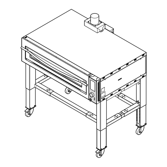
    SUPERTOP - SUPERTOP VARIO Installation et branchements 3.4.b - Branchement équipotentiel (Fig. 6) FIG. 6 L’appareil doit être inséré dans un système équipotentiel dont l efficacité doit tre vérifiée d après les normes en vigueur. Enlever le carter (1) après avoir dévissé les vis (2) (Fig.
  • Page 131 SUPERTOP - SUPERTOP VARIO Installation et branchements FIG. 8 3.5.a - Montage de la cheminée (Fig. 8) 120 mm • Monter le boîtier (1) sur la partie supérieure du four, en le vissant à l'aide des vis (2). • Monter la cheminée ( ) en la fi ant sur le bo tier (1) à...
  • Page 132: Utilisation Prévue

    SUPERTOP - SUPERTOP VARIO Sécurité Chapitre 4 4.1 - UTILISATION PRÉVUE Danger Tension insérée IMPORTANT Les fours Mod. SUPER TOP sont des fours professionnels pour la cuisson de pizzas et de produits semblables. • Ne pas effectuer de travaux lorsque la tension est Les différents modèles ne peuvent être utili-...
  • Page 133: Sécurités

    SUPERTOP - SUPERTOP VARIO Sécurité 4.4 - SECURITE Le four est pourvu des systèmes de sécurité suivants: 1)Toutes les zones dangereuses sont fermées par une protection («carter») par des vis. 2) Chaque four est pourvu d’un thermostat de sécurité qui éteint le four en cas de température trop élevée enregistrée à...
  • Page 134 SUPERTOP - SUPERTOP VARIO Fonctionnement Chapitre 5 Le fonctionnement du four pour toutes les compositions Le Mod. 635 L peut contenir n° 6 pizzas Ø 30 ou Ø 35 est toujours individuel donc pour les versions à deux cm, n°2 pizzas Ø 45 cm ou n°2 plaques à pizza 60x40 chambres ou à...
  • Page 135 SUPERTOP - SUPERTOP VARIO Fonctionnement SUPERTOP VARIO Le Mod. 440 peut contenir n° 4 pizzas Ø 40 cm ou n° Le Mod. 640 L peut contenir n° 6 pizzas Ø 40 cm ou n° 2 plaques 60x40 cm positionnées comme d’après le 3 ou 4 plaques 60x40 cm positionnées comme d’après...
  • Page 136 SUPERTOP - SUPERTOP VARIO Fonctionnement FIG. 1 5.1 - BANDEAU DU FOUR À COMMANDES NUMÉRIQUES (Fig. 1) www.oemali.com L'appareil présente les commandes suivantes : fficheur L'afficheur montre toutes les fonctions concernant le fonctionnement du four, les alarmes, les valeurs paramétrables, etc.
  • Page 137: Interface Utilisateur

    SUPERTOP - SUPERTOP VARIO Fonctionnement FIG. 2 5.2 - INTERFACE UTILISATEUR (Fig. 2) Lorsque le four est sous tension, la page-écran suivante s'affiche : 1. Calendrier Affiche le our de la semaine, le mois et l'année. 2. Langue Un drapeau indique la langue sélectionnée.
  • Page 138 SUPERTOP - SUPERTOP VARIO Fonctionnement 5.3 - PAGE-ÉCRAN PRINCIPALE (Fig. 3) FIG. 3 Une fois le four mis en route, l'utilisateur voit s'afficher la page-écran principale suivante : 1. Température Affiche la température actuelle de la chambre. 2. Résistance voûte Affiche le pourcentage sélectionné...
  • Page 139: Programmation Des Paramètres De Cuisson

    SUPERTOP - SUPERTOP VARIO Fonctionnement 5.4 - SÉLECTION DES PROGRAMMES OU MODI- FIG. 4 FICATION DES PARAMÈTRES (Fig. 4) En tournant la poignée (1) vers la gauche, on sélectionne les ic nes partir du bas de l affichage; en tournant droite, on sélectionne les icônes à...
  • Page 140 SUPERTOP - SUPERTOP VARIO Fonctionnement Par e emple, pour modifier la température de cuisson, FIG. 5 il est nécessaire (Fig.5): • Se positionner sur la valeur modifier (2). • Appuyer sur le bouton, la valeur (2) passe du blanc au rouge; l'icône sélectionnée (3) clignote.
  • Page 141: Menu Utilisateur

    2. MENU DE SERVICE FIG. 7 Menu dédié à un usage interne « OEM » ou à un personnel spécialisé, protégé par un mot de passe. 3. MINUTERIE POUR AUTO-ALLUMAGE Il est possible de paramétrer la date, l'heure et le programme pour l'allumage automatique du four.
  • Page 142 SUPERTOP - SUPERTOP VARIO Fonctionnement 5.8 - MINUTERIE POUR AUTO-ALLUMAGE Le menu utilisateur permet d'accéder au paramétrage FIG. 8a de la minuterie pour l'auto-allumage en sélectionnant l'icône « ». Ce menu permet de configurer deu allumages par our sur le programme souhaité (Fig. 8a).
  • Page 143: Calendrier

    SUPERTOP - SUPERTOP VARIO Fonctionnement 5.9 - CALENDRIER FIG. 9 Le menu utilisateur permet d'accéder au paramétrage du calendrier en sélectionnant l'icône « ». 1. Jour de la semaine La sélection de ce champ permet de paramétrer le jour de la semaine.
  • Page 144: Affichage Des Recettes Et Manuel

    SUPERTOP - SUPERTOP VARIO Fonctionnement 5.10 - AFFICHAGE DES RECETTES ET MANUEL FIG.10 Dans cette section du menu il est possible de lire les recettes et le manuel mémorisés. Sélectionner l’icône “ ” pour avoir accès à la Page d affichage ( ig. 10).
  • Page 145 SUPERTOP - SUPERTOP VARIO Fonctionnement Pour sortir de l’écran USB, appuyer sur l’icône (9). 5.11 - MODE DE SAISIE DES RECETTES Pour réaliser le TÉLÉCHARGEMENT sur la clé USB: Pour pouvoir utiliser cette fonction, les programmes pour PC suivants sont exigés : •...
  • Page 146 SUPERTOP - SUPERTOP VARIO Fonctionnement • Sur la barre d'outils, sélectionner • Enregistrer l'image dans le dossier « recettes » (créé Image, Decrease color depth et configurer 2 6 Colors spécialement à cet effet) avec le numéro de page (8 BPP).
  • Page 147 SUPERTOP - SUPERTOP VARIO Fonctionnement • Mettre le dossier Recettes (contenant les fichiers FIG. 12 convertis) sur une clé USB (compatible avec le sys- tème). • Allumer le four et accéder au menu USB spécial à l'aide de la touche (1) (Fig. 12).
  • Page 148: Préparation Du Four

    SUPERTOP - SUPERTOP VARIO Fonctionnement 5.12 - PREPARATION DU FOUR IMPORTANT Il est possible d’avoir deux types de cuissons de la pizza: Les paramètres peuvent varier d’après le la cuisson directe sur le plano réfractaire et la cuisson sur moule à pizza.
  • Page 149: Cuisson De La Pizza

    SUPERTOP - SUPERTOP VARIO Fonctionnement Intensité Programme Type de cuisson Température Temps programme • 4 min • • Réfractaire 4 min • • • 4 min • 6 min • • Moule 6 min • • • 6 min 5.12.b Normes générales de cuisson sur moule à pizza •...
  • Page 150: Alarmes

    SUPERTOP - SUPERTOP VARIO Fonctionnement FIG.14 5.14 - ALARMES Défaillance de la cheminée (Fig. 13) Lorsque cette alarme survient, les pictogrammes (1) et (2) s'affichent. Cette alarme indique que le mouvement de la cheminée est défectueux. Éteindre le four et contacter l'assistance technique pour faire vérifier le moteur de la cheminée, le micro inter-...
  • Page 151 SUPERTOP - SUPERTOP VARIO Fonctionnement Sonde de température de la carte de puissance Sonde de température de la chambre coupée ou coupée ou déconnectée déconnectée Lorsque cette alarme survient, l'alarme NTC s'affiche. Lorsque cette alarme survient, l'alarme TC1 s'affiche. Cette alarme indique que la sonde de la carte de puis- Elle indique que la sonde de température de la chambre...
  • Page 152 SUPERTOP - SUPERTOP VARIO Fonctionnement Sonde de température du compartiment technique 5.14.a Alarmes option vapeur court-circuitée (uniquement pour le marché américain) Thermostat de sécurité Lorsque cette alarme survient, l'alarme TC2 s'affiche. Quand cet alarme s affiche, on verra sur l écran, c té...
  • Page 153: Mauvais Fonctionnement, Causes Et Remèdes

    SUPERTOP - SUPERTOP VARIO Fonctionnement 5.15 - COMMENT ETEINDRE LE FOUR (Fig. 16) Sonde en court-circuit Quand cet alarme s affiche, on verra sur l écran, c té • A la fine de la ournée de travail éteindre le four en du symbole pour l’option vapeur, le symbole (1) et (2).
  • Page 154: Entretien Ordinaire Et Programmé

    SUPERTOP - SUPERTOP VARIO Entretien Chapitre 6 6.1 - ENTRETIEN ORDINAIRE ET PROGRAMME IMPORTANT Si on enlève courante avant que le cycle 6.1.a- Généralité de netto age finisse, il repartira automati- quement du début quand la courante sera remise en place.
  • Page 155: Nettoyage Externe

    SUPERTOP - SUPERTOP VARIO Entretien 6.1.b.b - Nettoyage externe FIG. 2 ATTENTION Netto er soigneusement le four la fin de chaque cycle de travail. Pour le nettoyage du four NE PAS UTILISER d’outillages métalliques comme pailles de fer, brosses, grattoirs, et/ou produits cor- rosifs.
  • Page 156: Nettoyage Du Ventilateur De Refroidisse- Ment Du Tableau Électrique

    SUPERTOP - SUPERTOP VARIO Entretien FIG. 4 (Version avec vitre extractible) • Enlever la vitre (1) avec les doigts ou en faisant levier à travers un utensile plat. • Remplacer l’ampoule (2). • Remonter la vitre (1) en la poussant vers l’encadre- ment (3).
  • Page 157: Réinitialisation Du Thermostat De Sécurité

    SUPERTOP - SUPERTOP VARIO Entretien FIG. 6 6.2 - RÉINITIALISATION DU THERMOSTAT DE SÉCURITÉ DANGER S'assurer qu'il n'y a pas de tension à l'inté- rieur du tableau électrique. Pour réinitialiser le thermostat de sécurité, procéder comme suit : • Dévisser les deux vis (1).
  • Page 158: Réinitialisation Thermostat De Sécurité Vaporisateur

    SUPERTOP - SUPERTOP VARIO Entretien 6.3 - RÉINITIALISATION THERMOSTAT FIG. 7 DE SÉCURITÉ VAPORISATEUR Pour réinitialiser le thermostat de sécurité, appuyer sur la touche rouge (1) qui sort du panneau (2). ATTENTION Si le thermostat se réintroduit plusieurs fois, le vaporisateur a quelques problèmes.
  • Page 159: Démontage De La Machine

    à ce qu’il est décrit, dans ces appareillages, peut provoquer des dom- consulter la société OEM, ou bien son mages aux personnes ou à l’environnement. L’écou- Agent, en s’adressant aux coordonnées lement des déchets électriques qui ne respectent...
  • Page 160 SUPERTOP - SUPERTOP VARIO Schema eletrique SCHÉMA DU FOUR « SUPER TOP » - 208/240 Volts 3Ph + PE FR - 48...
  • Page 161 SUPERTOP - SUPERTOP VARIO Schema eletrique LÉGENDE SCHÉMA DU FOUR « SUPER TOP » - 208/240 Volts 3Ph + PE RC1= Résistance voûte bouche RC2= Résistance voûte centre RC3= Résistance voûte fond RP1= Résistance sole bouche RP2= Résistance sole centre RP3= Résistance sole fond...
  • Page 162: Schéma Four "Super Top" 380/416 Volt 3Ph + N + Pe

    SUPERTOP - SUPERTOP VARIO Schema eletrique SCHÉMA DU FOUR « SUPER TOP » - 380/416 Volts 3Ph + N + PE FR - 50...
  • Page 163 SUPERTOP - SUPERTOP VARIO Schema eletrique LÉGENDE SCHÉMA DU FOUR « SUPER TOP » - 380/416 Volts 3Ph + N + PE RC1= Résistance voûte bouche RC2= Résistance voûte centre RC3= Résistance voûte fond RP1= Résistance sole bouche RP2= Résistance sole centre RP3= Résistance sole fond...
  • Page 164: Schéma Four "Super Top" 208/240 Volt 1Ph + N + Pe

    SUPERTOP - SUPERTOP VARIO Schema eletrique SCHÉMA DU FOUR « SUPER TOP » - 208/240 Volts 1Ph + N + PE FR - 52...
  • Page 165 SUPERTOP - SUPERTOP VARIO Schema eletrique LÉGENDE SCHÉMA DU FOUR « SUPER TOP » - 208/240 Volts 1Ph + N + PE RC1= Résistance voûte bouche RC2= Résistance voûte centre RC3= Résistance voûte fond RP1= Résistance sole bouche RP2= Résistance sole centre RP3= Résistance sole fond...
  • Page 166 SUPERTOP - SUPERTOP VARIO Schema eletrique SCHÉMA DU GÉNÉRATEUR DE VAPEUR POUR LE FOUR « VARIO » LÉGENDE SCHÉMA OM23.00500 SONDE DE TEMPÉRATURE ÉLECTROVANNE DE DISTRIBUTION TÉLÉRUPTEUR DE SÉCURITÉ RÉSISTANCE 1 GÉNÉRATEUR DE VAPEUR RÉSISTANCE 2 GÉNÉRATEUR DE VAPEUR RÉSISTANCE 3 GÉNÉRATEUR DE VAPEUR THERMOSTAT DE SÉCURITÉ...
  • Page 167 SUPERTOP - SUPERTOP VARIO Allgemeine Normen und Anmerkungen DEUTSCH 5.5 - PROGRAMMIERUNG DER GARPARAMETER ..27 KAPITEL ............5.6 - BELEUCHTUNG DER BACKKAMMER ...... 28 5.7 - BENUTZER MENÜ ............29 Kapitel für den Techniker und Bediener 5.8 - TIMER FÜR SELBSTEINSCHALTUNG ...... 30 1.1 -...
  • Page 168 SUPERTOP - SUPERTOP VARIO Allgemeine Normen und Anmerkungen DE - 2...
  • Page 169: Allgemeine Anmerkungen

    SUPERTOP - SUPERTOP VARIO Allgemeine Normen und Anmerkungen Abschnitt 1 1.1 - ALLGEMEINE ANMERKUNGEN - Die Stromzuführungsanlage des Ein- käufers muss mit einem automatischen - Vor dem Maschinenstarten soll der Benutzer Auslösungssystem über dem Ma- dieses Handbuch sorgfältig lesen, um die...
  • Page 170 SUPERTOP - SUPERTOP VARIO Allgemeine Normen und Anmerkungen - Der Boden in der Nähe des Ofens kann rut- - Die Maschine ist nur zum vorgesehenen, schig sein. Achtung! Geeignete rutschfeste belegten Zweck zu gebrauchen. Schuhe tragen. Die Maschine ist im Bezug auf technische Verfahrens-, Zeit-, Ortmerkmale gemäss der...
  • Page 171: Bezugsnormen

    SUPERTOP - SUPERTOP VARIO Allgemeine Normen und Anmerkungen 1.2 - BEZUGSNORMEN - Die Maschine und ihre Sicherheitsvorrichtungen sind GEFAHRLAGE nach den Normen, die in der Konformitätserklärung Aus Deutlichkeitsgründen wird die Ma- enthalten sind, gebaut worden. schine in einigen Abbildungen dieses Handbuchs ohne Schutzvorrichtungen 1.3 - BESCHREIBUNG DER SYMBOLE...
  • Page 172: Vorbereitungen Zu Lasten Des Einkäufers

    Maschine benötigten Stromwerts zu dimensionieren, sodaß ein 1.8 - SCHALLDRUCKPEGEL eventueller Stromabfall bei Volllast 2% unter- SUPERTOP / SUPERTOP VARIO-Öfen sind so gebaut schreitet. worden, da der fortdauernde gleichwertige gewogene A-Schalldruckpegel (dB) die maximal zulässige 70dB- c) Rauchabzugsvorbereitung.
  • Page 173 SUPERTOP - SUPERTOP VARIO Transport und Auspacken Abschnitt 2 AUSSENMASSE SUPERTOP 1170 2037 1590,5 (+325) (+325) 1200,5 (+325) 810,5 (+325) (+325) 1647 (+325) 1200,5 (+325) 810,5 (+325) (+325) min-max 0 - 32,5 cm Passo fori | Step holes Schritt Löcher | Trous step...
  • Page 174 SUPERTOP - SUPERTOP VARIO Transport und Auspacken AUSSENMASSE SUPERTOP VARIO PPA VA 1092 1282 (+325) (+325) (+325) (+325) PPA VA 1507 (+325) 1697 1226 (+325) (+325) (+325) (+325) min-max 0 - 32,5 cm PPA VA Passo fori | Step holes Schritt Löcher | Trous step...
  • Page 175: Technische Merkmale

    SUPERTOP - SUPERTOP VARIO Transport und Auspacken 2.1 - TECHNISCHE MERKMALE Modell 635S 208/240V 208/240V 380/416V 208/240V 208/240V 380/416V Elektrischer Anschluss 1Ph+PE 3Ph+PE 3Ph+N+PE 1Ph+PE 3Ph+PE 3Ph+N+PE 36,5A 21,5A 12,5A 45,7A 26,5A 15,5A Leistung 8,4 kW 10,5 kW 3 x 10 mm...
  • Page 176 SUPERTOP - SUPERTOP VARIO Transport und Auspacken Modell 640L Elektrischer 208/240V 208/240V 380/416V 208/240V 208/240V 380/416V Anschluss 1Ph+PE 3Ph+PE 3Ph+N+PE 1Ph+PE 3Ph+PE 3Ph+N+PE 88,7A 51,2A 29,6A 101,8A 58,8A 34,0A Leistung 20,4 w 2 ,4 w Kabelquerschnitt 3x25mm² 4x10mm² 5x6mm² 3x25mm²...
  • Page 177 SUPERTOP - SUPERTOP VARIO Transport und Auspacken Abmessung Position kW des elektrischen kW insgesamt Widerstands M ndungswiderstand Mittewiderst nde Decke Bodenwiderstand M ndungswiderstand Mittewiderst nde Boden Bodenwiderstand M ndungswiderstand 1,65 M ndungswiderstand 1,47 Mittewiderst nde 1,47 Decke Mittewiderst nde 1,47...
  • Page 178: Transport

    SUPERTOP - SUPERTOP VARIO Transport und Auspacken 2.2 - TRANSPORT ABB. 1 FIG. 1 2.2.a - Sendung (Abb. 1) Die Maschine wird in einem Umreifungs arton an einer durch Schrauben befestigten Holzpalette positioniert. Die Maschinensendung ann wie folgt erfolgen: Luftweg Bahn Die Wahl unter den verschiedenen Sendungsmöglich-...
  • Page 179: Eingangsprüfung

    SUPERTOP - SUPERTOP VARIO Transport und Auspacken 2.3 - EINGANGSPRÜFUNG FIG. 3 ABB. 3 Sich beim Eingang der Lieferung versichern, daß die Verpackung unversehrt und bei Sicht unbeschädigt ist. Ist das der Fall, ist die Verpackung laut Pos 2.4 zu entfer-...
  • Page 180: Identifikation Der Komponenten

    SUPERTOP - SUPERTOP VARIO Transport und Auspacken 2.5 - IDENTIFIKATION DER 2.6 - IDENTIFIKATION DER MASCHINE KOMPONENTEN (Abb. 4) (Abb. 4) 1. Datenschild Die enn Nummer der Maschine sowie die Daten zur 2. Ofen identifi ation der Maschine sind an einem Schild (1) an 3.
  • Page 181: Gerät-Aufheben

    SUPERTOP - SUPERTOP VARIO Maschinenaufstellung und - anschluss Abschnitt 3 ABB. 1 FIG. 1 GEFAHRLAGE Nur befugtes Fachpersonal darf die in die- sem Abschnitt beschriebenen Verfahren durchführen. 3.1 - GERÄT-AUFHEBEN (Abb. 1) Das Gerät ist durch einen Kran oder einen Flaschenzug wie folgt aufzuheben: •...
  • Page 182 SUPERTOP - SUPERTOP VARIO Maschinenaufstellung und - anschluss FIG. 3 ABB. 3 Montage von Einzelkammeröfen (Abb. 3) • An dem Untergestell (2) den Backofen (1) positionie- ren und es an der rechten und linken Seite mit den Schrauben (3) befestigen.
  • Page 183: Elektrischer Anschluss

    SUPERTOP - SUPERTOP VARIO Maschinenaufstellung und - anschluss 3.4 - ELEKTRISCHER ANSCHLUSS GEFAHRLAGE Vor der Durchführung des elektrischen GEFAHRLAGEN Anschlusses sichergehen, daß der LEI- • Die elektrische Speiseleitung ist mit einem TUNGSTRENNSCHALTER ausgeschaltet ist angemessenen, allpoligen LEITUNGSTRENN- (die Leitung steht nicht unter Spannung).
  • Page 184: Ofen-Positionierung

    SUPERTOP - SUPERTOP VARIO Maschinenaufstellung und - anschluss 3.4.b - Äquipotentieller Anschluss (Abb. 6) ABB. 6 FIG. 6 Die Anlage ist in ein äquipotentielles System, dessen Wirksamkeit nach den geltenden Normen festzustellen ist, einzusetzen. Die Schrauben (2) abschrauben, um das Gehäuse (1) abzunehmen (Abb.
  • Page 185 SUPERTOP - SUPERTOP VARIO Maschinenaufstellung und - anschluss FIG. 8 ABB. 8 3.5.a - Montage des Kamins (Abb. 8) 120 mm • Die Schrauben (2) festziehen, um das Gehäuse (1) am oberen Teil des Ofens anzumontieren. • Den Kamin (3) mit der Platte (4) mit den Schrauben (5) auf dem Gehäuse (1) montieren.
  • Page 186: Vorgesehene Anwendung

    Benutzung lehnt der Hersteller irgendwelche Haftung ab, in diesem Fall entfallen auch eventuelle Ga- rantierechte. 4.2 - FALSCHE ANWENDUNG Die Öfen Mod. SUPERTOP - SUPERTOP VARIO wurden rein für die Zubereitung von FIG. 1 ABB. 1 Lebensmittel entworfen und gebaut. Es ist...
  • Page 187: Sicherheitsvorrichtungen

    SUPERTOP - SUPERTOP VARIO Sicherheitsvorrichtungen 4.4 - SICHERHEITSVORRICHTUNGEN Die Anlage ist mit folgenden Sicherheitsvorrichtungen versehen: 1) Alle gefährlichen Stellen sind durch Kästen mit Schrauben geschlossen. 2) Jeder Ofen ist mit einem Sicherheitsthermostat, der bei Übertemperatur in der Backkammer den Ofen ausschaltet, versehen, bei Öfen mit Digitalsteuerung...
  • Page 188 SUPERTOP - SUPERTOP VARIO Maschinenbetrieb Abschnitt 5 Das Modell 635 L kann Nr. 6 Pizzen (Ø30cm oder Bei allen Ofenzusammensetzungen handelt es sich Ø35cm), Nr. 2 ø45cm Pizzen oder Nr. 2 60x40 Pizza- immer um Einzelfunktionieren, daher ist es möglich bei...
  • Page 189 SUPERTOP - SUPERTOP VARIO Maschinenbetrieb SUPERTOP VARIO Das Mod. 440 kann 4 Pizzen Ø 40 cm oder 2 60x40 Das Mod. 640 L kann 6 Pizzen Ø 40 cm oder 3-4 60x40 cm Backformen enthalten, die als folgendes Schema cm Backformen enthalten, die als folgendes Schema...
  • Page 190: Steuertafel Für Digitale Öfen

    SUPERTOP - SUPERTOP VARIO Maschinenbetrieb ABB. 1 FIG. 1 5.1 - STEUERTAFEL FÜR DIGITALE ÖFEN (Abb. 1) www.oemali.com Auf der Maschine sind folgende Steuerungen: 1. Display Auf dem Display werden alle un tionen f r den Betrieb des Ofens, die Alarmmeldungen, die einge- stellten erte usw.
  • Page 191: Benutzerschnittstelle

    SUPERTOP - SUPERTOP VARIO Maschinenbetrieb ABB. 2 FIG. 2 5.2 - BENUTZERSCHNITTSTELLE (Abb. 2) Die Versorgung des fens auf dem Display wird in der folgenden Bildschirmseite angezeigt: 1. Kalender Zeigvt den Wochentag, den Monat und das Jahr an. 2. Sprache Mit einer ahne wird die eingestellte Sprache ange- zeigt.
  • Page 192 SUPERTOP - SUPERTOP VARIO Maschinenbetrieb 5.3 - HAUPTBILDSCHIRMSEITE (Abb. 3) ABB. 3 FIG. 3 Nach der inschaltung des fens wird die folgende Hauptseite für den Benutzer angezeigt: 1. Temperatur Zeigt die aktuelle Temperatur in der Backkammer an 2. Deckenwiderstand eigt den eingestellten Prozentsatz der Dec enwi- derstände an.
  • Page 193: Programmierung Der Garparameter

    SUPERTOP - SUPERTOP VARIO Maschinenbetrieb 5.4 - PROGRAMMAUSWAHL ODER PARAME- ABB. 4 FIG. 4 TERÄNDERUNG (Abb. 4) enn Sie den nopf (1) nach lin s drehen, w hlen Sie die Symbole von unten im Display aus. wenn Sie nach rechts rotieren, w hlen Sie die Symbole von oben aus.
  • Page 194: Beleuchtung Der Backkammer

    SUPERTOP - SUPERTOP VARIO Maschinenbetrieb FIG. 5 ABB. 5 Um beispielsweise die artemperatur zu ndern, muss man (Abb. 5): • Sich auf den zu ändernden Wert (2) positionieren. • Den Drehknopf drücken, damit der Wert (2) von Weiß auf Rot wechselt; das ausgew hlte Symbol ( ) blin t.
  • Page 195: Benutzer Menü

    SUPERTOP - SUPERTOP VARIO Maschinenbetrieb 5.7 - MENÜ BENUTZER (Abb. 7) Für den Zugriff auf das Menü Benutzer das Ikon “ ” anw hlen In diesem Menü können alle Funktionen für den Benut- zer angew hlt und eingestellt werden. Durch Betätigen des Drehknopfs kann man sich auf die Ikons positionieren und die betreffenden Parameter einstellen: 1.
  • Page 196: Timer Für Selbsteinschaltung

    SUPERTOP - SUPERTOP VARIO Maschinenbetrieb 5.8 - TIMER FÜR SELBSTEINSCHALTUNG ABB. 8a Vom Menü Benutzer gelangt man zur Einstellung des FIG. 8a Timers für die Selbsteinschaltung, indem man das Ikon “ ” anw hlt. Mit diesem Men nne t glich zwei inschaltvorg nge im gew nschten Programm (Abb.
  • Page 197: Kalender

    SUPERTOP - SUPERTOP VARIO Maschinenbetrieb 5.9 - KALENDER ABB. 9 FIG. 9 Vom Menü Benutzer gelangt man zur Einstellung des Kalenders, indem man das Ikon “ ” anw hlt 1. Wochentag Durch Anw hlen dieses eldes ann der ochentag eingestellt werden.
  • Page 198: Anzeige Der Rezepte Und Handbuch

    SUPERTOP - SUPERTOP VARIO Maschinenbetrieb 5.10 - ANZEIGE DER REZEPTE UND HANDBUCH ABB.10 FIG.10 In diesem Teil des Menüs können Sie die Rezepte und das Handbuch im Speicher lesen. Für den Zugriff auf die Seite das Ikon “ ” ausw hlen (Abb.
  • Page 199: Angabemodus Der Rezepte

    SUPERTOP - SUPERTOP VARIO Maschinenbetrieb Um den USB-Bildschirm zu verlassen, drücken Sie das 5.11 - EINGABEMODUS DER REZEPTE Symbol (9). Für das HERUNTERLADEN auf USB-Stick: Um diese Funktion benutzen zu können, sind folgende Rechnerprogramme erforderlich: Paint ( indows Anwendung) •...
  • Page 200 SUPERTOP - SUPERTOP VARIO Maschinenbetrieb • Auf der Toolleiste Image, Decrease color depth an- • Das Bild im Ordner "Rezepte" (eigens angelegt) mit w hlen und 2 6 Colors ( BPP) einstellen. der Seitennummer und der eweiligen Sprache spei- chern, z.B. "01de" Bitmap mit 24 Bit bis zu maximal 51 Seiten (von 00de bis 50de).
  • Page 201 SUPERTOP - SUPERTOP VARIO Maschinenbetrieb • rdner Rezepte (mit den umgewandelten ABB. 12 FIG. 12 Dateien) auf einen (mit dem System kompatiblen) USB-Stick verschieben. • Den Ofen einschalten und mit der Taste (1) (Abb. 12) in das betreffende Menü USB-Stick gehen.
  • Page 202 SUPERTOP - SUPERTOP VARIO Maschinenbetrieb 5.12 - OFENVORBEREITUNG WICHTIG Die Pizza ann entweder dire t an der hitzebest ndigen Die Parameter können sich je nach dem Fläche oder in der Backform erfolgen. benutzten Pizzateig ändern. Nachfolgend finden Sie einige inweise bez glich der Einstellung der verschiedenen Parameter.
  • Page 203: Pizzabacken

    SUPERTOP - SUPERTOP VARIO Maschinenbetrieb Programm- Programm Backtyp Temperatur Zeit intensität • 4 min • • Auf feuerfestem Stein 4 min • • • 4 min • 6 min • • Backform 6 min • • • 6 min 5.13 - PIZZABACKEN 5.12.b - Allgemeine Anweisungen zum Backen in...
  • Page 204: Alarmmeldungen

    SUPERTOP - SUPERTOP VARIO Maschinenbetrieb ABB.14 FIG.14 5.14 - ALARMMELDUNGEN Betriebsstörung des Kamins (Abb. 13) enn dieser Alarm auf dem Display angezeigt wird, werden die Symbole (1) und (2) angezeigt Dieser Alarm zeigt an, dass an der Bewegung des a- mins eine Störung vorliegt.
  • Page 205 SUPERTOP - SUPERTOP VARIO Maschinenbetrieb Temperaturfühler der Leistungsplatine unterbrochen Temperaturfühler in der Kammer unterbrochen oder oder abgetrennt abgetrennt enn dieser Alarm ausgel st wird, wird auf dem Display enn dieser Alarm ausgel st wird, wird auf dem Display der Alarm "NTC" angezeigt der Alarm "TC1"...
  • Page 206 SUPERTOP - SUPERTOP VARIO Maschinenbetrieb Kurzschluss des Temperaturfühlers im technischen 5.14.a Dampfer-Alarm Fach (nur für den amerikanischen Markt) enn dieser Alarm ausgel st wird, wird auf dem Display Sicherheit-Thermostat der Alarm "TC2" angezeigt enn es diesen Alarm auf dem Display gibt, wird neben Gibt an, dass sich ein Kurzschluss des Temperaturfühler...
  • Page 207: Ausschaltung

    SUPERTOP - SUPERTOP VARIO Maschinenbetrieb 5.15 - AUSSCHALTUNG (Abb. 16) Kurzschluss des Sensors enn es diesen Alarm auf dem Display gibt, wird neben • Am Ende des Arbeitstags ist der Ofen durch aus- dem Dampfer-Symbol das Symbol (1) und (2) angezeigt.
  • Page 208: Ordentliche Und Eingeplante Instandhaltung

    SUPERTOP - SUPERTOP VARIO Instandhaltung Abschnitt 6 6.1 - ORDENTLICHE UND EINGEPLANTE WICHTIG INSTANDHALTUNG Wenn man die Elektrizität vom Ofen ab- nehmen wird, vorher des Ende der Säu- 6.1.a- Allgemeine Daten berungsreihe, wird sie automatisch vom Anfang aufnehmen sobald die Elektrizität GEFAHRLAGE eingeführt wird.
  • Page 209: Aussenreinigung

    SUPERTOP - SUPERTOP VARIO Instandhaltung 6.1.b.b - Aussenreinigung ABB. 2 FIG. 2 ACHTUNG Am Ende jedes Arbeitskreislaufs ist der Ofen sorgfältig zu reinigen. Zur Ofenreinigung sind KEINE Metallgegen- stände wie Metallwolle, Bürsten, Schaber und/oder Ätzmittel zu benutzen. • Zur Aussenreinigung ist ein (mit Wasser und für die zu reinigende Fläche geeignetem Reinigungsmittel)
  • Page 210: Reinigung Des Kühllüfters Der Elektrischen Schalttafel

    SUPERTOP - SUPERTOP VARIO Instandhaltung FIG. 4 ABB. 4 (Version mit herausnehmbarem Glas) • Mit den ingern oder einem lachwer zeug das las entfernen (1). • Glühbirne austauschen (2). • las nach Rahmen dr c en ( ) um es wieder zu- sammenzusetzen (1).
  • Page 211: Rücksetzung Des Sicherheitsthermostats

    SUPERTOP - SUPERTOP VARIO Instandhaltung ABB. 6 FIG. 6 6.2 - RÜCKSETZUNG DES SICHERHEITSTHERMOSTATS GEFAHRLAGE Sicherstellen, dass im Schaltschrank keine Spannung anliegt. r die R c setzung des Sicherheitsthermostats wie folgt vorgehen: • Die beiden Schrauben (1) aufschrauben. • Die Tür öffnen und die Schraube (2) aufschrauben.
  • Page 212: Reaktivierung Des Sicherheit-Thermostats Des Dampfkessels

    SUPERTOP - SUPERTOP VARIO Instandhaltung 6.3 - REAKTIVIERUNG DES FIG. 7 SICHERHEIT-THERMOSTATS DES DAMPFKESSELS Um den Sicherheitsthermostat wieder einzuschalten, drücken Sie die rote Taste (1), auf dem Panel (2). ACHTUNG Wenn der Thermostat mehrmals aktiv ist, zeigt es an, dass es ein Problem im Dampf- kessel gibt.
  • Page 213: Demontage Der Maschine

    Rahmen der Abfalltrennung als Industrieabfall derselben anders auszubauen, ist die Firma gesondert entsorgt werden mu . OEM oder ihre Vertretung zu kontaktieren Eine unangemessene oder nicht den gesetzlichen - zu diesem Zweck siehe Adressen auf der Vorschriften entsprechende Entsorgung von elekt- dritten Seite dieses Handbuchs.
  • Page 214 SUPERTOP - SUPERTOP VARIO Elektrischer schaltplan SCHEMA OFEN "SUPER TOP" - 208/240 Volt 3 Phasen + PE DE - 48...
  • Page 215 SUPERTOP - SUPERTOP VARIO Elektrischer schaltplan LEGENDE SCHEMA OFEN "SUPER TOP" - 208/240 Volt 3 Phasen + PE RC1= Widerstand Decke Öffnung RC2= Widerstand Decke Mitte RC3= Widerstand Decke Boden RP1= Widerstand Boden Öffnung RP2= Widerstand Boden Mitte RP3= Widerstand Boden Boden MV= Lüfter Haube...
  • Page 216 SUPERTOP - SUPERTOP VARIO Elektrischer schaltplan SCHEMA OFEN "SUPER TOP" - 380/416 Volt 3 Phasen + N + PE DE - 50...
  • Page 217 SUPERTOP - SUPERTOP VARIO Elektrischer schaltplan LEGENDE SCHEMA OFEN "SUPER TOP" - 380/416 Volt 3 Phasen + N + PE RC1= Widerstand Decke Öffnung RC2= Widerstand Decke Mitte RC3= Widerstand Decke Boden RP1= Widerstand Boden Öffnung RP2= Widerstand Boden Mitte RP3= Widerstand Boden Boden MV= Lüfter Haube...
  • Page 218: Schema Ofen "Super Top" 208/240 Volt 1Ph + N + Pe

    SUPERTOP - SUPERTOP VARIO Elektrischer schaltplan SCHEMA OFEN "SUPER TOP" - 208/240 Volt 1 Phase + N + PE DE - 52...
  • Page 219 SUPERTOP - SUPERTOP VARIO Elektrischer schaltplan LEGENDE SCHEMA OFEN "SUPER TOP" - 208/240 Volt 1 Phase + N + PE RC1= Widerstand Decke Öffnung RC2= Widerstand Decke Mitte RC3= Widerstand Decke Boden RP1= Widerstand Boden Öffnung RP2= Widerstand Boden Mitte RP3= Widerstand Boden Boden MV= Lüfter Haube...
  • Page 220: Schema Verdampfer Für Ofen „Vario

    SUPERTOP - SUPERTOP VARIO Elektrischer schaltplan SCHEMA VERDAMPFER FÜR OFEN „VARIO“ LEGENDE SCHEMA OM23.00500 TEMPERATURSONDE E-VENTIL ABGABE SICHERHEITSRELAIS WIDERSTAND 1 VERDAMPFER WIDERSTAND 2 VERDAMPFER WIDERSTAND 3 VERDAMPFER SICHERHEITSTHERMOSTAT VERDAMPFER DE - 54...
  • Page 221 SUPERTOP - SUPERTOP VARIO Normas y advertencias generales ESPAÑOL 5.5 - PROGRAMACIÓN PARÁMETROS DE COCCIÓN ..27 CAPÍTULO ............5.6 - ILUMINACIÓN CÁMARA ..........28 5.7 - MENÚ USUARIO ............29 Capítulo para el técnico y el operador 5.8 - TEMPORIZADOR AUTOENCENDIDO .......
  • Page 222 SUPERTOP - SUPERTOP VARIO Normas y advertencias generales ES - 2...
  • Page 223: Advertencias Generales

    SUPERTOP - SUPERTOP VARIO Normas y advertencias generales Capítulo 1 1.1 - ADVERTENCIAS GENERALES - La instalación de alimentación eléctrica del comprador tiene que contar con un sistema - Antes de poner en marcha la máquina, el de desconexión automático colocado antes operador tendrá...
  • Page 224 SUPERTOP - SUPERTOP VARIO Normas y advertencias generales - El piso cerca del horno puede ser resbaladizo: - Se prohíbe el uso de la máquina para usos tener cuidado. Utilizar zapatos antideslizan- diferentes de los expresamente previstos tes apropiados. y documentados.
  • Page 225: Normas De Referencia

    SUPERTOP - SUPERTOP VARIO Normas y advertencias generales 1.2 - NORMAS DE REFERENCIA PELIGRO - La máquina y sus dispositivos de seguridad han sido Para aclarar las informaciones, algunas fabricados de conformidad con las normas indicadas ilustraciones de este manual muestran en la declaración de conformidad.
  • Page 226: Conexiones A Cargo Del Comprador

    1.8 - NIVEL DE PRESIÓN ACÚSTICA resulte inferior al 2%. Los hornos modelos SUPERTOP / SUPERTOP VARIO han sido fabricados con el objetivo de mantener el nivel c) Preparación de la campana de aspiración.
  • Page 227: Espacio Ocupado

    SUPERTOP - SUPERTOP VARIO Transporte y desembalaje Capítulo 2 ESPACIO OCUPADO SUPERTOP 1170 2037 1590,5 (+325) (+325) 1200,5 (+325) 810,5 (+325) (+325) 1647 (+325) 1200,5 (+325) 810,5 (+325) (+325) min-max 0 - 32,5 cm Passo fori | Step holes Schritt Löcher | Trous step...
  • Page 228 SUPERTOP - SUPERTOP VARIO Transporte y desembalaje ESPACIO OCUPADO SUPERTOP VARIO PPA VA 1092 1282 (+325) (+325) (+325) (+325) PPA VA 1507 (+325) 1697 1226 (+325) (+325) (+325) (+325) min-max 0 - 32,5 cm PPA VA Passo fori | Step holes Schritt Löcher | Trous step...
  • Page 229: Características Técnicas

    SUPERTOP - SUPERTOP VARIO Transporte y desembalaje 2.1 - CARACTERÍSTICAS TÉCNICAS Modelo 635S Conexión 208/240V 208/240V 380/416V 208/240V 208/240V 380/416V eléctrica 1Ph+PE 3Ph+PE 3Ph+N+PE 1Ph+PE 3Ph+PE 3Ph+N+PE 36,5A 21,5A 12,5A 45,7A 26,5A 15,5A Potencia 8,4 kW 10,5 kW Sección del...
  • Page 230 SUPERTOP - SUPERTOP VARIO Transporte y desembalaje Modello 640L Conexión 208/240V 208/240V 380/416V 208/240V 208/240V 380/416V eléctrica 1Ph+PE 3Ph+PE 3Ph+N+PE 1Ph+PE 3Ph+PE 3Ph+N+PE 88,7A 51,2A 29,6A 101,8A 58,8A 34,0A Potencia 20,4Kw 23,4Kw Sección del 3x25mm² 4x10mm² 5x6mm² 3x25mm² 4x16mm² 5x10mm²...
  • Page 231 SUPERTOP - SUPERTOP VARIO Transporte y desembalaje Tamaño Posición KW Resistencia KW totales Resistencia boca Resistencias centro cielo Resistencia fondo Resistencia boca Resistencias centro fondo Resistencia fondo Resistencia boca 1,65 Resistencia boca 1,47 Resistencias centro 1,47 cielo Resistencias centro 1,47...
  • Page 232: Transporte

    SUPERTOP - SUPERTOP VARIO Transporte y desembalaje 2.2 - TRANSPORTE FIG. 1 2.2.a - Envío (Fig. 1) La m quina se posiciona sobre un pallet de madera, fi a- do por medio de tornillos, en una ca a de cart n fle eada.
  • Page 233: Controles Al Recibir El Producto

    SUPERTOP - SUPERTOP VARIO Transporte y desembalaje 2.3 - CONTROLES AL RECIBIR EL FIG. 3 PRODUCTO Al recibir el suministro, controle que el embalaje esté íntegro y no haya sufrido daños a simple vista. Si está ntegro, quite el embala e como se especifica en el punto 2.4 (excepto en casos de instrucciones diferentes...
  • Page 234: Identificación De La Máquina

    SUPERTOP - SUPERTOP VARIO Transporte y desembalaje 2.5 - IDENTIFICACIÓN DE LOS COMPONEN- 2.6 - IDENTIFICACIÓN DE LA MÁQUINA TES (Fig. 4) (Fig. 4) l n mero de matr cula y los datos para la identificaci n 1. Chapa de datos de la máquina están troquelados en la chapa (1) que se...
  • Page 235: Ensamblaje De Los Componentes

    SUPERTOP - SUPERTOP VARIO Instalación y conexión Capítulo 3 FIG. 1 PELIGRO Todas las operaciones descritas en este capítulo tienen que ser efectuadas por un técnico especializado y habilitado. 3.1 - ELEVACIÓN DEL APARATO (Fig. 1) La elevación del aparato se debe efectuar mediante una grúa o un aparejo actuando como sigue:...
  • Page 236 SUPERTOP - SUPERTOP VARIO Instalación y conexión FIG. 3 Montaje del horno monocámara (Fig. 3) • Apoye el horno (1) sobre el soporte (2) y fíjelo con los dos tornillos (3) del lado derecho e izquierdo. Montaje de hornos bicámara o tricámara (Fig. 4) •...
  • Page 237: Conexión Eléctrica

    SUPERTOP - SUPERTOP VARIO Instalación y conexión 3.4 - CONEXIÓN ELÉCTRICA PELIGRO Antes de realizar la conexión eléctrica, ase- PELIGRO gurarse de que el SECCIONADOR de LÍNEA • La línea eléctrica de alimentación debe esté desconectado (línea no bajo tensión).
  • Page 238 SUPERTOP - SUPERTOP VARIO Instalación y conexión FIG. 6 3.4.b - Conexión equipotencial (Fig. 6) El aparato tiene que estar conectado en un sistema equipotencial cuya eficacia tiene que comprobarse de acuerdo a las normas vigentes. Quitar el cárter (1) desenroscando los tornillos (2) (Fig. 5).
  • Page 239 SUPERTOP - SUPERTOP VARIO Instalación y conexión FIG. 8 3.5.a - Montaje de la chimenea (Fig. 8) 120 mm • Montar la caja (1) en la parte superior del horno enroscándola con los tornillos (2) • Montar la chimenea (3) bloqueándola en la caja (1) mediante la placa (4) con los tornillos (5).
  • Page 240: Uso Previsto

    RESPONSABILIDAD POR ACCIDENTES A PERSONAS O COSAS Y HACE CADUCAR LA GARANTÍA. 4.2 - USO INCORRECTO Los hornos Mod. SUPERTOP - SUPERTOP FIG. 1 VARIO se han diseñado y construido para un uso exclusivamente alimentario, por lo que está prohibido: - el uso del horno a operadores no profe- sionales;...
  • Page 241: Dispositivos De Seguridad

    SUPERTOP - SUPERTOP VARIO Dispositivos de seguridad 4.4 - DISPOSITIVOS DE SEGURIDAD El aparato está dotado de los siguientes sistemas de seguridad: 1) Todas las zonas peligrosas están cerradas por medio de cárteres con tornillos. 2) Cada horno está dotado de un termostato de segu- ridad que lo apaga en caso de que se detecte un recalentamiento dentro de la cámara de cocción.
  • Page 242 SUPERTOP - SUPERTOP VARIO Funcionamiento Capítulo 5 nes es siempre individual y por lo tanto es posible para El Mod. 635 L puede contener 6 pizzas de Ø 30 o Ø las versiones bicámara o tricámara plantear dos o tres 35 cm, 2 pizzas de Ø...
  • Page 243 SUPERTOP - SUPERTOP VARIO Funcionamiento SUPERTOP VARIO El Mod. 440 puede contener n° 4 pizzas Ø 40 cm o n° El Mod. 640 L puede contener n° 6 pizzas Ø 40 cm o n° 2 bandejas 60x40 cm colocadas según este esquema.
  • Page 244 SUPERTOP - SUPERTOP VARIO Funcionamiento FIG. 1 5.1 - PANEL DE MANDOS DIGITALES DEL HOR- NO (Fig. 1) www.oemali.com En la máquina se encuentran los siguientes mandos: 1. Pantalla En la pantalla aparecen todas las funciones relativas al funcionamiento del horno, las alarmas, los valores configurables, etc.
  • Page 245: Interfaz De Usuario

    SUPERTOP - SUPERTOP VARIO Funcionamiento FIG. 2 5.2 - INTERFAZ DE USUARIO (Fig. 2) Cuando se alimenta el horno en la pantalla se visualiza la siguiente pantalla: 1. Calendario Visualiza día de la semana, mes y año. 2. Idioma Mediante una bandera se visualiza el idioma confi- gurado.
  • Page 246: Pantalla Principal

    SUPERTOP - SUPERTOP VARIO Funcionamiento 5.3 - PANTALLA PRINCIPAL (Fig. 3) FIG. 3 Después del arranque del horno la pantalla principal para el uso del usuario es la siguiente: 1. Temperatura Visualiza la tempera presente en la cámara en ese momento 2.
  • Page 247: Selección Programas O Modificació

    SUPERTOP - SUPERTOP VARIO Funcionamiento 5.4 - SELECCIÓN PROGRAMAS O MODIFICA- FIG. 4 CIÓN DE LOS PARÁMETROS (Fig. 4) Girando el pomo (1) hacia la izquierda, se seleccionan los iconos empezando desde abajo del display; girando hacia la derecha, se seleccionan los iconos empezando desde arriba.
  • Page 248 SUPERTOP - SUPERTOP VARIO Funcionamiento Por ejemplo, para cambiar la temperatura de cocción FIG. 5 es necesario: • Posicionarse en el valor a cambiar (2). • Pulsar el pomo, el valor (2) cambia de blanco a rojo; el icono seleccionado (3) parpadea.
  • Page 249: Menú Servicio

    Se puede configurar el idioma seleccionando la bandera correspondiente. FIG. 7 2. MENÚ SERVICIO Menú dedicado para uso interno de "OEM" o personal especializado, protegido por contraseña. 3. TEMPORIZADOR DE ENCENDIDO AUTOMÁTICO Se puede configurar la fecha, la hora y el programa para el encendido automático del horno.
  • Page 250: Temporizador Autoencendido

    SUPERTOP - SUPERTOP VARIO Funcionamiento 5.8 - TEMPORIZADOR DE ENCENDIDO AUTO- MÁTICO FIG. 8a Desde el men usuario se accede a la configuraci n del temporizador de encendido automático seleccionando el icono “ ”. Mediante este men se pueden configurar dos encen- didos diarios en el programa deseado (Fig.
  • Page 251: Calendario

    SUPERTOP - SUPERTOP VARIO Funcionamiento 5.9 - CALENDARIO FIG. 9 Desde el men usuario se accede a la configuraci n del calendario seleccionando el icono “ ” 1. Día de la semana Seleccionando este campo se puede configurar el día de la semana.
  • Page 252 SUPERTOP - SUPERTOP VARIO Funcionamiento 5.10 - VISUALIZACIÓN DE LAS RECETAS Y DEL FIG.10 MANUAL En esta sección del menú se pueden leer las recetas y el manual memorizados. Seleccionar el icono “ ” y acceder a la página de visualización (Fig.
  • Page 253: Modalidad Introducción Recetas

    SUPERTOP - SUPERTOP VARIO Funcionamiento Para salir de la panorámica USB, pulsar el icono (9). 5.11 - MODALIDAD INTRODUCCIÓN RECETAS Para realizar la DESCARGA en la memoria USB: Para poder utilizar esta función son necesarios los si- guientes programas para el ordenador: •...
  • Page 254 SUPERTOP - SUPERTOP VARIO Funcionamiento • Guardar la imagen en la carpeta “recetas” (creada • Seleccionar en la barra de herramientas espec ficamente) con el n mero de p gina y el idio- Image, Decrease color depth y configurar 2 6 Colors ma relativo, ejemplo: “01it”...
  • Page 255 SUPERTOP - SUPERTOP VARIO Funcionamiento • Poner la carpeta recetas (que contiene los archivos FIG. 12 convertidos) en un dispositivo USB (compatible con el sistema). • Encender el horno y entrar en el menú USB mediante la tecla (1) (Fig. 12).
  • Page 256: Preparación Del Horno

    SUPERTOP - SUPERTOP VARIO Funcionamiento 5.12 - PREPARACIÓN DEL HORNO IMPORTANTE Se pueden efectuar dos tipos de cocción de la pizza, Los parámetros pueden variar según el tipo la cocción directa en el plano refractario y la cocción en bandeja.
  • Page 257: Cocción De La Pizza

    SUPERTOP - SUPERTOP VARIO Funcionamiento Intensidad Programa Tipo de cocción Temperatura Tiempo programa • 4 min • • Refractario 4 min • • • 4 min • 6 min • • Bandeja 6 min • • • 6 min 5.12.b Normas generales de la cocción en bandeja •...
  • Page 258: Alarmas

    SUPERTOP - SUPERTOP VARIO Funcionamiento FIG.14 5.14 - ALARMAS Mal funcionamiento de la chimenea (Fig. 13) Cuando se visualiza esta alarma en la pantalla aparece el símbolo (1) y el símbolo (2) Esta alarma indica que existe un fallo en el desplaza- miento de la chimenea.
  • Page 259 SUPERTOP - SUPERTOP VARIO Funcionamiento Sonda de temperatura de la cámara interrumpida o Sonda de temperatura de la tarjeta de potencia in- desconectada terrumpida o desconectada Cuando se activa esta alarma en la pantalla aparece Cuando se activa esta alarma en la pantalla aparece la alarma "TC1"...
  • Page 260 SUPERTOP - SUPERTOP VARIO Funcionamiento Sonda de temperatura del compartimiento técnico 5.14.a Alarmas vaporera en cortocircuito (solo para el mercado americano) Termostato de seguridad Cuando se activa esta alarma en la pantalla aparece Cuando aparece esta alarma en la pantalla, al lado del la alarma "TC2"...
  • Page 261: Funcionamientos Anómalos, Causasy Soluciones

    SUPERTOP - SUPERTOP VARIO Funcionamiento 5.15 - APAGADO (Fig. 16) Sonda en cortocircuito • Al final de la ornada de traba o apague el horno pul- Cuando aparece esta alarma en la pantalla, al lado del símbolo de la vaporera, aparece el símbolo (1) y (2).
  • Page 262: Mantenimiento Ordinario Y Programado

    SUPERTOP - SUPERTOP VARIO Mantenimiento Capítulo 6 6.1 - MANTENIMIENTO ORDINARIO Y PRO- IMPORTANTE GRAMADO Si por cualquiera raz n antes del final del ciclo de limpieza se quita la electricidad 6.1.a- Generalidades al horno, cuando se vuelve a encender el horno, el programa en automático se pone...
  • Page 263: Limpieza Plano Refractario

    SUPERTOP - SUPERTOP VARIO Mantenimiento FIG. 2 ATENCIÓN impie con cuidado el horno al finalizar cada ciclo de trabajo. Para la limpieza del horno NO use utensilios metálicos como por ejemplo estropajos, ce- pillos, espátulas, y/o productos corrosivos. NO utilice chorros de agua sobre las pare- des del horno.
  • Page 264: Limpieza Del Ventilador De Refrigeración Del Cuadro Eléctrico

    SUPERTOP - SUPERTOP VARIO Mantenimiento FIG. 4 (Versión con vidrio extraíble) • Quitar el vidrio (1) por los dedos o sopalancando por un utensilio llano. • Reemplazar la bombilla (2). • Reensamblar el vidrio (1) empujandolo hacia el marco (3).
  • Page 265: Rearme Del Termostato De Seguridad

    SUPERTOP - SUPERTOP VARIO Mantenimiento FIG. 6 6.2 - REARME DEL TERMOSTATO DE SEGU- RIDAD PELIGRO Asegurarse de que no haya tensión dentro del cuadro eléctrico. Para rearmar el termostato de seguridad, realizar lo siguiente: • Desenroscar los dos tornillos (1).
  • Page 266: Rearme Termostato De Seguridad Vaporera

    SUPERTOP - SUPERTOP VARIO Mantenimiento 6.3 - REARME TERMOSTATO DE FIG. 7 SEGURIDAD VAPORERA Para rearmar el termostato de seguridad, pulsar la tecla roja (1) que sobresale del panel (2). ATENCIÓN Si el termostato se reactiva varias veces, sig- nifica que la vaporera tiene alg n problema.
  • Page 267: Desmontaje De La Máquina

    La OEM o con el propio Agente, consultando eliminación de residuos eléctricos que no respete las los datos que se encuentran en la tercera normas vigentes conlleva la aplicación de sanciones...
  • Page 268 SUPERTOP - SUPERTOP VARIO Esquema electrico ESQUEMA HORNO “SUPER TOP” - 208/240 Volt 3Ph + PE ES - 48...
  • Page 269 SUPERTOP - SUPERTOP VARIO Esquema electrico LEYENDA ESQUEMA HORNO “SUPER TOP” - 208/240 Volt 3Ph + PE RC1= Resistencia Superior Boca RC2= Resistencia Superior Centro RC3= Resistencia Superior Fondo RP1= Resistencia inferior Boca RP2= Resistencia inferior Centro RP3= Resistencia inferior Fondo...
  • Page 270: Esquema Horno "Super Top" 380/416 Volt 3Ph + N + Pe

    SUPERTOP - SUPERTOP VARIO Esquema electrico ESQUEMA HORNO “SUPER TOP” - 380/416 Volt 3Ph + N + PE ES - 50...
  • Page 271 SUPERTOP - SUPERTOP VARIO Esquema electrico LEYENDA ESQUEMA HORNO “SUPER TOP” - 380/416 Volt 3Ph + N + PE RC1= Resistencia Superior Boca RC2= Resistencia Superior Centro RC3= Resistencia Superior Fondo RP1= Resistencia inferior Boca RP2= Resistencia inferior Centro RP3= Resistencia inferior Fondo...
  • Page 272: Esquema Horno "Super Top" 208/240 Volt 1Ph + N + Pe

    SUPERTOP - SUPERTOP VARIO Esquema electrico ESQUEMA HORNO “SUPER TOP” - 208/240 Volt 1Ph + N + PE ES - 52...
  • Page 273 SUPERTOP - SUPERTOP VARIO Esquema electrico LEYENDA ESQUEMA HORNO “SUPER TOP” - 208/240 Volt 1Ph + N + PE RC1= Resistencia Superior Boca RC2= Resistencia Superior Centro RC3= Resistencia Superior Fondo RP1= Resistencia inferior Boca RP2= Resistencia inferior Centro RP3= Resistencia inferior Fondo...
  • Page 274: Esquema Vaporera Para Horno "Vario

    SUPERTOP - SUPERTOP VARIO Esquema electrico ESQUEMA VAPORERA PARA HORNO "VARIO" LEYENDA ESQUEMA OM23.00500 SONDA DE TEMPERATURA ELECTROVÁLVULA DE SUMINISTRO TELERRUPTOR DE SEGURIDAD RESISTENCIA 1 VAPORERA RESISTENCIA 2 VAPORERA RESISTENCIA 3 VAPORERA TERMOSTATO DE SEGURIDAD VAPORERA ES - 54...
  • Page 276 OEM ALI Group S.r.l. a Socio Unico Viale Lombardia, 33 Tel.: +39 0376 - 910511 Fax: +39 0376 - 920754 www.oemali.com info@oemali.com...

Ce manuel est également adapté pour:

Supertop vario

Table des Matières