Télécharger Imprimer la page

Optika Italy SLX Serie Manuel D'instructions

Masquer les pouces Voir aussi pour SLX Serie:

Publicité

Les langues disponibles
  • FR

Les langues disponibles

  • FRANÇAIS, page 74

Liens rapides

SLX Series
INSTRUCTION MANUAL
Model
SLX-1
SLX-2
SLX-3
SLX-4
SLX-5
Ver. 2.4
2023

Publicité

loading

Sommaire des Matières pour Optika Italy SLX Serie

  • Page 1 SLX Series INSTRUCTION MANUAL Model SLX-1 SLX-2 SLX-3 SLX-4 SLX-5 Ver. 2.4 2023...
  • Page 2 Table of Contents Warning Safety Information Package content SLX-1 SLX-2 / SLX-3 SLX-4 / SLX-5 Unpacking Intended use Symbols and conventions Instrument description SLX-1 SLX-2 / SLX-3 SLX-4 / SLX-5 Assembly Assembling procedure 8.1.1 SLX-1 / SLX-2 / SLX-3 8.1.2 SLX-4 / SLX-5 Use of the microscope Adjust interpupillary distance...
  • Page 3 Warning This microscope is a scientific precision instrument designed to last for many years with a minimum of maintenance. It is built to high optical and mechanical standards and to withstand daily use. We remind you that this manual contains important information on safety and maintenance, and that it must therefore be made accessible to the instrument users.
  • Page 4 Package content SLX-1 ① ⑤ ④ ③ ⑥ ② ① Microscope body ④ Stage clips (one pair) ② Eyepieces ⑤ Dust cover ③ Microscope stand ⑥ Power supply SLX-2 / SLX-3 ① ⑤ ④ ② ③ ⑥ ⑦ ① Microscope body ⑤ Dust Cover • SLX-2: binocular ⑥ Power supply • SLX-3: trinocular ⑦ Allen Wrench (SLX-3 only) ② Eyepieces • SLX-2: one (2mm)
  • Page 5 SLX-4 / SLX-5 ① ③ ⑤ ② ⑥ ④ ① Microscope body ③ Overhanging stand • SLX-4: binocular ④ Focus • SLX-4: trinocular ⑤ Dust cover ② Eyepieces ⑥ Allen wrench Page 5...
  • Page 6 Unpacking The microscope is housed in a moulded Styrofoam container. Remove the tape from the edge of the container and lift the top half of the container. Take some care to avoid that the optical items (objectives and eyepieces) fall out and get dam- aged.
  • Page 7 Instrument description SLX-1 TRANSPORTATION HANDLE EYEPIECES FOCUS KNOB MICROSCOPE BODY MAGNIFICATION CHANGER STAGE CLIPS TRANSMITTED LIGHT ON/OFF AND INCIDENT LIGHT INTENSITY CONTROL ILLUMINATOR STAND INCIDENT LIGHT ON/OFF AND INTENSITY CONTROL TRANSLUCENT DISC (TRANSMITTED LIGHT) Page 7...
  • Page 8 SLX-2 / SLX-3 PHOTO/TV PORT TRANSPORTATION (ONLY SLX-3) HANDLE EYEPIECES ZOOM KNOB FOCUS KNOB MICROSCOPE BODY -) SLX-2: BINOCULAR -) SLX-3: TRINOCULAR STAGE CLIPS TRANSMITTED LIGHT ON/OFF AND INTENSITY CONTROL INCIDENT LIGHT ILLUMINATOR STAND INCIDENT LIGHT ON/OFF AND INTENSITY CONTROL TRANSLUCENT DISC (TRANSMITTED LIGHT) Page 8...
  • Page 9 SLX-4 / SLX-5 EYEPIECES PHOTO/TV PORT VERTICAL ARM (ONLY SLX-5) FIXING KNOB PILLAR HORIZONTAL ARM FIXING KNOBS ZOOM KNOB MICROSCOPE BODY -) SLX-4: BINOCULAR -) SLX-5: TRINOCULAR DROP PREVENTION RING FIXING KNOB FOCUS HANDLE BASE Page 9...
  • Page 10 Assembly Assembling procedure 8.1.1 SLX-1 / SLX-2 / SLX-3 • The microscope is shipped from the factory without bat- teries. 1. Open the lid of the battery compartment. (Fig. 1) F ig. 1 ig. 1 2. Insert 3x AA NiMh 1.2V rechargeable batteries (respecting the polarity of each battery).
  • Page 11 6. Remove the eyepieces dust caps and insert the eyepieces in the empty eyepiece sleeve. (Fig. 5) F ig. 5 ig. 5 7. Connect the jack of the power supply to the socket in the rear part of the microscope base. (Fig. 6) F ig.
  • Page 12 3. Insert the drop preventing ring and fix it at the desired height by screwing the fixing knob. (Fig. 9) F ig. 9 ig. 9 4. Insert the horizontal arm and secure it with the fixing screw ①. (Fig. 10 - 11) F ig.
  • Page 13 5. Install the head holder. Unscrew the locking knob ③ and in- sert the arm for the focus support from above ② into the hole of the horizontal arm. (Fig. 12 - 13) 6. Once fully inserted, tighten the fixing screw ④ (Fig. 13) ②...
  • Page 14 Use of the microscope Adjust interpupillary distance 1. Hold the right and left eyepiece tube with both hands and ad- just the interpupillary distance by moving the two parts (Fig. 16) until one circle of light can be seen. • If two circles appear, the interpupillary distance is too big.
  • Page 15 Diopter compensation • This compensation makes possible for people wearing ③ glasses to adjust the microscope to their eyes and use the microscope without glasses. 1. Put the zoom ② down to the lowest magnification and focus the specimen with the focusing knobs ③. (Fig. 19) 2.
  • Page 16 Use of additional lens • Additional lenses can be used on models SLX-2 / SLX-3 / SLX-4 / SLX-5. 1. Screw the desired additional lens on the microscope body. (Fig. 14) • Each additional lens has a specific Working Distance (see table below).
  • Page 17 9.6.2 Use of 1.5X additional lens (ST-086.1) 1.5X additional lens has a Working Distance of 47 mm and, in case of very thin specimens (when working with SLX-2 / SLX-3 models), the microscope cannot get a proper focus. In order to overcome this effect, the 1.5X lens is provided with a transparent spacer ④ that must be placed on the base plate (Fig.
  • Page 18 • Use without eyeglasses Raise eye shields and observe at the microscope placing eyes to the shields, avoiding external light to disturb the observation. (Fig. 30) F ig. 30 ig. 30 9.10 Use of overhanging stand Moving the horizontal arm 1.
  • Page 19 Rotating the horizontal arm 1. Loosen the horizontal arm fixing knob ② and rotate the arm, then tighten again the fixing knob. (Fig. 34) • NOTE: 180° rotation of the microscope with respect to the base could cause a rollover of the entire system. ③...
  • Page 20 10. Microphotography 10.1 Use of C-mount adapter 1. Loosen the clamping screw ① on the trinocular port and re- move the dust cap ②. (Fig. 35) ② ① F ig. 35 ig. 35 2. Screw the C-mount adapter ③ to the camera ④ and insert the round dovetail of the C-mount into the empty hole of the trinocular port (Fig.
  • Page 21 11. Maintenance Microscopy environment This microscope is recommended to be used in a clean, dry and shock free environment with a temperature of 5°-40°C and a maximum relative humidity of 75 % (non condensing). Use a dehumidifier if needed. To think about when and after using the microscope •...
  • Page 22 12. Troubleshooting Review the information in the table below to troubleshoot operating problems. PROBLEM CAUSE SOLUTION I. Optical Section: The illumination is ON, but the field of The plug is not connected to the illu- Connect the cable view is dark. mination The brightness is too low Adjust to a proper setting...
  • Page 23 Equipment disposal Art.13 Dlsg 25 July 2005 N°151. “According to directives 2002/95/EC, 2002/96/EC and 2003/108/EC relating to the reduc- tion in the use of hazardous substances in electrical and electronic equipment and waste disposal.” The basket symbol on equipment or on its box indicates that the product at the end of its useful life should be collected sep- arately from other waste.
  • Page 24 OPTIKA S.r.l. ® Via Rigla, 30 - 24010 Ponteranica (BG) - ITALY Tel.: +39 035.571.392 info@optikamicroscopes.com - www.optikamicroscopes.com OPTIKA Spain spain@optikamicroscopes.com OPTIKA USA usa@optikamicroscopes.com OPTIKA China china@optikamicroscopes.com OPTIKA India india@optikamicroscopes.com OPTIKA Central America camerica@optikamicroscopes.com...
  • Page 25 Serie SLX MANUALE DI ISTRUZIONI Modello SLX-1 SLX-2 SLX-3 SLX-4 SLX-5 Ver. 2.4 2023...
  • Page 26 Indice Avvertenza Informazioni sulla sicurezza Contenuto della confezione SLX-1 SLX-2 / SLX-3 SLX-4 / SLX-5 Disimballaggio Utilizzo previsto Simboli Descrizione dello strumento SLX-1 SLX-2 / SLX-3 SLX-4 / SLX-5 Assemblaggio Procedura di assemblaggio 8.1.1 SLX-1 / SLX-2 / SLX-3 8.1.2 SLX-4 / SLX-5 Uso del microscopio Regolare la distanza interpupillare...
  • Page 27 Avvertenza Questo microscopio è uno strumento scientifico di alta precisione, progettato per durare a lungo con una minima manutenzione; la realizzazione è secondo i migliori standard ottici e meccanici, per poter essere utilizzato quotidianamente. Vi ricordiamo che questo manuale contiene informazioni importanti per la sicurezza e per la manutenzione dello strumento, e deve quindi essere messo a disposizione di coloro che lo utilizzeranno.
  • Page 28 Contenuto della confezione SLX-1 ① ⑤ ④ ③ ⑥ ② ① Corpo microscopio ④ Mollettine fermacampione (una coppia) ② Oculari ⑤ Copertina antipolvere ③ Stativo microscopio ⑥ Alimentatore SLX-2 / SLX-3 ① ⑤ ④ ② ③ ⑥ ⑦ ① Corpo microscopio ⑤ Copertina antipolvere ⑥ Alimentatore • SLX-2: binoculare ⑦ Chiave a brugola • SLX-3: trinoculare ② Oculari...
  • Page 29 SLX-4 / SLX-5 ① ③ ⑤ ② ⑥ ④ ① Corpo microscopio ③ Base a sbalzo ④ Messa a fuoco • SLX-4: binoculare ⑤ Copertina antipolvere • SLX-4: trinoculare ② Oculari ⑥ Chiave a brugola Pagina 29...
  • Page 30 Disimballaggio Il microscopio è riposto in un imballo di polistirolo espanso. Rimuovere il nastro adesivo dal collo ed aprire la parte superiore dell’imballo. Fare attenzione a non far cadere le parti ottiche (obiettivi e oculari) nell’estrarre il microscopio dalla scatola per evitare che vengano danneggiati.
  • Page 31 Descrizione dello strumento SLX-1 MANIGLIA DI TRASPORTO OCULARI MANOPOLA DI MESSA A FUOCO CORPO MICROSCOPIO VARIATORE DI INGRANDIMENTO MOLLETTINE MANOPOLA ON/OFF E ILLUMINATORE CONTROLLO INTENSITÀ LUCE INCIDENTE LUCE TRASMESSA STATIVO MANOPOLA ON/OFF E CONTROLLO INTENSITÀ LUCE INCIDENTE DISCO OPALINO (LUCE TRASMESSA) Pagina 31...
  • Page 32 SLX-2 / SLX-3 USCITA FOTO/TV MANIGLIA DI (SOLO SLX-3) TRASPORTO OCULARI MANOPOLA ZOOM MANOPOLA DI MESSA A FUOCO CORPO MICROSCOPIO -) SLX-2: BINOCULARE -) SLX-3: TRINOCULARE MOLLETTINE MANOPOLA ON/OFF E CONTROLLO INTENSITÀ LUCE TRASMESSA ILLUMINATORE LUCE INCIDENTE BASE MANOPOLA ON/OFF E CONTROLLO INTENSITÀ...
  • Page 33 SLX-4 / SLX-5 OCULARI USCITA FOTO/TV (SOLO SLX-5) MANOPOLA FISSAGGIO BRACCIO VERTICALE COLONNA MANOPOLE FISSAGGIO MANOPOLA BRACCIO ORIZZONTALE ZOOM CORPO MICROSCOPIO -) SLX-4: BINOCULARE -) SLX-5: TRINOCULARE ANELLO PREVENZIONE DISCESA MANOPOLA DI BLOCCO MANOPOLA DI MESSA A FUOCO BASE Pagina 33...
  • Page 34 Assemblaggio Procedura di assemblaggio 8.1.1 SLX-1 / SLX-2 / SLX-3 • Il microscopio viene spedito dalla fabbrica senza batte- rie. 1. Aprire il coperchio del vano batterie. (Fig. 4) F ig. 1 ig. 1 2. Inserire 3 batterie ricaricabili AA NiMh 1,2V (rispettando la polarità...
  • Page 35 6. Rimuovere i tappi antipolvere dai portaoculari ed inserire gli oculari nei portaoculari vuoti. (Fig. 5) F ig. 5 ig. 5 7. Inserire lo spinotto dell’alimentatore nel connettore posto nel- la parte posteriore della base. (Fig. 6) F ig. 6 ig.
  • Page 36 3. Inserire l’anello di prevenzione discesa e fissarlo all’altezza desiderata avvitando la manopola di fissaggio. (Fig. 9) F ig. 9 ig. 9 4. Inserire il braccio orizzontale e bloccarlo con la vite di fissag- gio ①. (Fig. 10-11) F ig. 10 ig.
  • Page 37 5. Installare il supporto per la testa. Svitare la manopola di bloc- co ③ ed inserire dall’alto il braccio per il supporto della mes- sa a fuoco ② dall’alto nel foro del braccio orizzontale. (Fig. 12 - 13) 6. Una volta inserito a fondo bloccare la vite di fissaggio ④. ②...
  • Page 38 Uso del microscopio Regolare la distanza interpupillare 1. Tenere la parte destra e sinistra della testa d’osservazione usando entrambe le mani e regolare la distanza interpupilla- re ruotando le due parti (Fig. 16) fino ad ottenere la visione di un unico cerchio di luce. •...
  • Page 39 Compensazione diottrica • Questa compensazione consente ai portatori di occhiali di adattare il microscopio alla propria vista ed usare il ③ microscopio senza occhiali. 1. Portare lo zoom al minimo ingrandimento ② e mettere a fuo- co con le manopole di messa a fuoco ③. (Fig. 19) 2.
  • Page 40 Uso di lenti addizionali • Le lenti addizionali possono essere utilizzate sui modelli SLX-2 / SLX-3 / SLX-4 / SLX-5. 1. Avvitare la lente addizionale al corpo del microscopio. (Fig. • Ogni lente ha una specifica Distanza di Lavoro. • (Solo SLX-2 / SLX-3): La corsa del supporto di messa a fuo- co potrebbe non compensare le diverse distanza di lavoro delle varie lenti addizionali.
  • Page 41 9.6.2 Uso della lente addizionale 1.5X (ST-086.1) La lente aggiuntiva 1.5X ha una distanza di lavoro di 47 mm e, in caso di campioni molto sottili (quando si lavora con i modelli SLX-2 / SLX-3), il microscopio non riesce ad ottenere una messa a fuoco adeguata.
  • Page 42 • Uso senza occhiali da vista Rialzare i paraocchi ed osservare al microscopio appoggiando gli occhi ai paraocchi, in modo da evitare che la luce esterna arrivi a disturbare l’occhio. (Fig. 30) F ig. 30 ig. 30 9.10 Uso della base a sbalzo Spostare il braccio orizzontale 1.
  • Page 43 Ruotare il braccio orizzontale 1. Allentare la vite di fissaggio del braccio orizzontale ③ e ruotare il braccio, quindi serrare la vite di fissaggio. (Fig. 34) • NOTA: Una rotazione del microscopio di 180° rispetto alla base potrebbe causare un rovesciamento di tutto il sistema.
  • Page 44 Microfotografia 10.1 Uso di telecamere a passo “C” 1. Allentare la vite di bloccaggio ① sul tubo trinoculare e rimuo- vere il tappo antipolvere ②. (Fig. 35) ② ① F ig. 35 ig. 35 2. Avvitare l’adattatore passo “C” ③ alla telecamera ④ e in- stallare l’attacco rotondo del passo C nel foro vuoto del tubo trinoculare (Fig.
  • Page 45 11. Manutenzione Condizioni ambientali Questo microscopio è consigliato per l’uso in un ambiente pulito, asciutto e privo di urti con una temperatura di 5°-40°C e un’umidità relativa massima del 75% (senza condensa). Se necessario, utilizzare un deumidificatore. Prima e dopo l’utilizzo del microscopio •...
  • Page 46 12. Risoluzione dei problemi Consultare le informazioni contenute nella tabella seguente per risolvere i problemi di funzionamento. PROBLEMA CAUSA SOLUZIONE I. Sezione Ottica: L’illuminazione è accesa ma il campo I connettori dell’alimentatore non sono Collegarli visivo è scuro. ben collegati La luminosità...
  • Page 47 Smaltimento Ai sensi dell’articolo 13 del decreto legislativo 25 luglio 2005 n°151. “Attuazione delle direttive 2002/95/CE, 2002/96/CE e 2003/108/CE, relative alla riduzione dell’uso di sostanze pericolose nelle apparecchiature elettriche ed elettroniche, nonché allo smaltimento dei rifiuti”. Il simbolo del cassonetto riportato sulla apparecchiatura o sulla sua confezione indica che il prodotto alla fine della propria vita utile deve essere raccolto separatamente degli altri rifiuti.
  • Page 48 OPTIKA S.r.l. ® Via Rigla, 30 - 24010 Ponteranica (BG) - ITALY Tel.: +39 035.571.392 info@optikamicroscopes.com - www.optikamicroscopes.com OPTIKA Spain spain@optikamicroscopes.com OPTIKA USA usa@optikamicroscopes.com OPTIKA China china@optikamicroscopes.com OPTIKA India india@optikamicroscopes.com OPTIKA Central America camerica@optikamicroscopes.com...
  • Page 49 Serie SLX MANUAL DE INSTRUCCIONES Modelo SLX-1 SLX-2 SLX-3 SLX-4 SLX-5 Ver. 2.4 2023...
  • Page 50 Índice Advertencia Información de seguridad Contenido del paquete SLX-1 SLX-2 / SLX-3 SLX-4 / SLX-5 Desembalaje Utilización Símbolos Descripción del instrumento SLX-1 SLX-2 / SLX-3 SLX-4 / SLX-5 Montaje Procedimiento de montaje 8.1.1 SLX-1 / SLX-2 / SLX-3 8.1.2 SLX-4 / SLX-5 Uso del microscopio Ajustar la distancia interpupilar Enfoque...
  • Page 51 Advertencia Este microscopio es un instrumento científico de precisión. Su utilización está pensada para una larga duración con un mínimo nivel de mantenimiento. Para su fabricación se han utilizado elementos ópticos y mecánicos de elevada calidad que lo convierten en el instrumento ideal para la utilización diaria en las aulas y el laboratorio. Informamos que esta guía contiene importantes informaciones sobre la seguridad y el mantenimiento del producto y por lo tanto debe ser accesible a todos aquellos que utilizan dicho instrumento.
  • Page 52 Contenido del paquete SLX-1 ① ⑤ ④ ③ ⑥ ② ① Cuerpo microscopio ④ Clips de muestra (un par) ② Oculares ⑤ Cubierta antipolvo ③ Base microscopio ⑥ Fuente de alimentación SLX-2 / SLX-3 ① ⑤ ④ ② ③ ⑥ ⑦ ① Cuerpo microscopio ⑤ Cubierta antipolvo • SLX-2: binocular ⑥ Fuente de alimentación • SLX-3: trinocular ⑦ Llave Allen ② Oculares...
  • Page 53 SLX-4 / SLX-5 ① ③ ⑤ ② ⑥ ④ ① Cuerpo microscopio ③ Base en voladizo • SLX-4: binocular ④ Enfoque • SLX-4: trinocular ⑤ Cubierta antipolvo ② Oculares ⑥ Llave Allen Página 53...
  • Page 54 Desembalaje El microscopio esta embalado dentro de una caja de porexpan. Quitar el precinto que hay alrededor de la caja y abrirla. Tenga cuidado al abrir la caja ya que algunos accesorios ópticos como objetivos y oculares podrían caerse o dañarse. Con las dos manos (una sujetando el brazo y la otra la base) extraer el microscopio de dentro la caja de porexpan y poner sobre la mesa, procurando que ésta sea fuerte y estable.
  • Page 55 Descripción del instrumento SLX-1 ASA DE TRANSPORTE OCULARES MANDO DE ENFOQUE CUERPO MICROSCOPIO VARIADOR DE AUMENTO CLIPS DE MUESTRA PERILLA DE ENCENDIDO/ APAGADO Y CONTROL DE ILUMINADOR DE LA INTENSIDAD DE LA LUZ LUZ INCIDENTE TRANSMITIDA BASE PERILLA DE ENCENDIDO/ APAGADO Y CONTROL DE LA INTENSIDAD DE LA LUZ INCIDENTE...
  • Page 56 SLX-2 / SLX-3 PUERTO DE FOTO/TV ASA DE (SÓLO SLX-3) TRANSPORTE OCULARES MANDO ZOOM MANDO DE ENFOQUE CUERPO MICROSCOPIO -) SLX-2: BINOCULAR -) SLX-3: TRINOCULAR PERILLA DE ENCENDIDO/ CLIPS DE MUESTRA APAGADO Y CONTROL DE LA INTENSIDAD DE LA LUZ TRANSMITIDA ILUMINADOR DE LUZ INCIDENTE...
  • Page 57 SLX-4 / SLX-5 OCULARES PUERTO DE FOTO/TV (SÓLO SLX-5) POMO DE FIJACIÓN BRAZO VERTICAL PILAR POMOS DE FIJACIÓN BRAZO HORIZONTAL MANDO ZOOM CUERPO MICROSCOPIO -) SLX-4: BINOCULAR -) SLX-5: TRINOCULAR ANILLO DE PREVENCIÓN DE CAÍDAS POMO DE FIJACIÓN MANDO DE ENFOQUE BASE Página 57...
  • Page 58 Montaje Procedimiento de montaje 8.1.1 SLX-1 / SLX-2 / SLX-3 • El microscopio se envía de fábrica sin baterías. 1. Abrir la tapa del compartimento de la pila. (Fig. 1) F ig. 1 ig. 1 2. Inserte 3 pilas recargables AA NiMh 1,2 V (respetando la po- laridad de cada pila).
  • Page 59 6. Retire las tapas de polvo de los oculares e inserte los ocula- res en la funda vacía del ocular. (Fig. 5) F ig. 5 ig. 5 7. Conecte la clavija de la fuente de alimentación a la toma si- tuada en la parte posterior de la base del microscopio.
  • Page 60 3. Inserte el anillo de prevención de caídas y fíjelo a la altura deseada atornillando el pomo de fijación. (Fig. 9) F ig. 9 ig. 9 4. Insertar el brazo horizontal y fijarlo con el tornillo de fijación ①. (Fig. 10 -11) F ig.
  • Page 61 5. Instale el soporte de enfoque. Desenrosque el botón de pre- vención ② e inserte el brazo de soporte de cabeza ① desde arriba en el orificio del brazo horizontal. (Fig. 12) 6. Una vez insertado completamente, apriete el tornillo de fija- ción ④ (Fig.
  • Page 62 Uso del microscopio Ajustar la distancia interpupilar 1. Sostenga el tubo del ocular derecho e izquierdo con ambas manos y ajuste la distancia interpupilar moviendo las dos partes (Fig. 16) hasta que se pueda ver un círculo de luz. • Si aparecen dos círculos, la distancia interpupilar es dema- siado grande.
  • Page 63 Compensación dioptrica • Esta compensación permite a las personas que llevan gafas ajustar el microscopio a sus ojos y utilizar el mi- ③ croscopio sin gafas. 1. Ponga el zoom ② en la ampliación más baja y enfoque el espécimen con los mandos de enfoque ③. (Fig. 19) 2.
  • Page 64 Uso de lentes adicionales • Se pueden utilizar lentes adicionales en los modelos SSLX-2 / SLX-3 / SLX-4 / SLX-5. 1. Atornille la lente adicional deseada en el cuerpo del micros- copio. (Fig. 23) • Cada lente adicional tiene una distancia de trabajo específi- ca (véase la tabla siguiente).
  • Page 65 9.6.2 Uso de lente adicional 1.5X (ST-086.1) La lente adicional de 1.5X tiene una distancia de trabajo de 47 mm y, en el caso de muestras muy delgadas (cuando se trabaja con los modelos SLX-2 / SLX-3), el microscopio no puede obte- ner un enfoque adecuado.
  • Page 66 • Uso sin gafas Levante los protectores oculares y observe en el microscopio colocando los ojos lo más cerca posible sobre los oculares, evitando que penetre luz externa. (Fig. 30) F ig. 30 ig. 30 9.10 Uso de base en voladizo Mover el brazo horizontal 1.
  • Page 67 Girar el brazo horizontal 1. Afloje el tornillo de fijación del brazo horizontal ② y gire el brazo, luego apriete el tornillo de fijación. (Fig. 34) • NOTA: Girar el microscopio 180° desde la base puede causar que todo el sistema se vuelque. ③...
  • Page 68 10. Microfotografía 10.1 Uso de cámaras de paso “C” 1. Aflojar el tornillo ① del tubo trinocular y quitar la tapa negra ②. (Fig. 35) ② ① F ig. 35 ig. 35 ③ ④ 2. Colocar el adaptador paso C a la cámara e insertar el conjunto sobre el puerto trinocular (Fig.
  • Page 69 11. Mantenimiento Ambiente de trabajo Se aconseja utilizar este microscopio en un ambiente limpio y seco; también se deben evitar los impactos. La temperatura de trabajo recomendada es de 0-40°C y la humedad relativa máxima es de 85 % (en ausencia de condensación). Si es necesario, utilizar un deshumidificador.
  • Page 70 12. Guía de solución de problemas Revisar la información en la tabla a continuación para solucionar problemas de funcionamiento. PROBLEMA CAUSA SOLUCIÓN I. Sección Óptica: El iluminador está encendido, pero el El enchufe no está conectado al siste- Conectar campo visible está oscuro ma de iluminación La luminosidad es demasiado baja Regular la luminosidad...
  • Page 71 Medidas ecológicas y reciclaje De conformidad con el artículo 13 del Decreto Legislativo Nº 151, de 25 de julio de 2005. “Aplicación de las Directivas 2002/95/CE, 2002/96/CE y 2003/108/CE sobre la reducción del uso de sustancias peligrosas en aparatos eléctricos y elec- trónicos y la eliminación de residuos.
  • Page 72 OPTIKA S.r.l. ® Via Rigla, 30 - 24010 Ponteranica (BG) - ITALY Tel.: +39 035.571.392 info@optikamicroscopes.com - www.optikamicroscopes.com OPTIKA Spain spain@optikamicroscopes.com OPTIKA USA usa@optikamicroscopes.com OPTIKA China china@optikamicroscopes.com OPTIKA India india@optikamicroscopes.com OPTIKA Central America camerica@optikamicroscopes.com...
  • Page 73 Série SLX MANUEL D’UTILISATION Modèle SLX-1 SLX-2 SLX-3 SLX-4 SLX-5 Ver. 2.4 2023...
  • Page 74 Sommaire Avertissement Précautions Contenu de l’emballage SLX-1 SLX-2 / SLX-3 SLX-4 / SLX-5 Déballage Emploi prévu Symboles Description de l’instrument SLX-1 SLX-2 / SLX-3 SLX-4 / SLX-5 Assemblage Assemblage du microscope 8.1.1 SLX-1 / SLX-2 / SLX-3 8.1.2 SLX-4 / SLX-5 Utilisation du microscope Ajuster la distance interpupillaire Mise au point...
  • Page 75 Avertissement Le présent microscope est un appareil scientifique de précision créé pour offrir une durée de vie de plusieurs années avec un niveau d’entretien minimum. Les meilleurs composants optiques et mécaniques ont été utilisés pour sa conception ce qui fond de lui un appareil idéal pour une utilisation journalière. Ce guide contient des informations importantes sur la sécurité...
  • Page 76 Contenu de l’emballage SLX-1 ① ⑤ ④ ③ ⑥ ② ① Corps du microscope ④ Clips de échantillon (une paire) ② Oculaires ⑤ Housse de protection ③ Statif du microscope ⑥ Alimentation électrique SLX-2 / SLX-3 ① ⑤ ④ ② ③ ⑥ ⑦ ① Corps du microscope ⑤ Housse de protection • SLX-2: binoculaire ⑥ Alimentation électrique • SLX-3: trinoculaire ⑦ Clé Allen ② Oculaires...
  • Page 77 SLX-4 / SLX-5 ① ③ ⑤ ② ⑥ ④ ① Corps du microscope ③ Support en surplomb • SLX-4: binoculaire ④ Mise au point • SLX-5: trinoculaire ⑤ Housse de protection ② Oculaires ⑥ Clé Allen Page 77...
  • Page 78 Déballage Le microscope est logé dans un récipient moulé en polystyrène. Retirez le ruban adhésif du bord du conteneur et soulevez la moitié supérieure du conteneur. Faites attention à ce que les éléments optiques (objectifs et oculaires) ne tombent pas et ne soient pas endommagés.
  • Page 79 Description de l’instrument SLX-1 POIGNÉE DE TRANSPORT OCULAIRES BOUTON DE MISE AU POINT CORPS DU MICROSCOPE VARIATEUR DE GROSSISSEMENT CLIPS DE ÉCHANTILLON BOUTON MARCHE/ ARRÊT ET RÉGLAGE ILLUMINATEUR DE L’INTENSITÉ DE LA DE LUMIÈRE LUMIÈRE TRANSMISE INCIDENTE BASE BOUTON MARCHE/ ARRÊT ET RÉGLAGE DE L’INTENSITÉ...
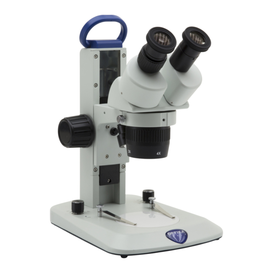
  • Page 80 SLX-2 / SLX-3 POIGNÉE DE SORTIE PHOTO/TV TRANSPORT (SLX-3 UNIQUEMENT) OCULAIRES BOUTON DE ZOOM BOUTON DE MISE AU POINT CORPS DU MICROSCOPE -) SLX-2: BINOCULAIRE -) SLX-3: TRINOCULAIRE CLIPS DE ÉCHANTILLON BOUTON MARCHE/ ARRÊT ET RÉGLAGE DE L’INTENSITÉ DE LA ILLUMINATEUR LUMIÈRE TRANSMISE DE LUMIÈRE...
  • Page 81 SLX-4 / SLX-5 OCULAIRES SORTIE PHOTO/TV (SLX-5 UNIQUEMENT) BOUTON DE FIXATION DU BRAS VERTICAL PILIER BOUTONS DE FIXATION BOUTON DE DU BRAS HORIZONTAL ZOOM CORPS DU MICROSCOPE -) SLX-4: BINOCULAIRE -) SLX-5: TRINOCULAIRE ANNEAU DE PRÉVENTION DE DESCENTE MOLETTE DE FIXATION BOUTON DE MISE AU POINT...
  • Page 82 Assemblage Assemblage du microscope 8.1.1 SLX-1 / SLX-2 / SLX-3 • Le microscope est expédié d’usine sans piles. 1. Ouvrir le couvercle du compartiment des piles. (Fig. 1) F ig. 1 ig. 1 2. Insérer 3 piles rechargeables AA NiMh 1,2V (en respectant la polarité de chaque pile). (Fig. 2) 3.
  • Page 83 6. Retirez les capuchons anti-poussière des oculaires et insé- rez les oculaires dans la douille vide de l’oculaire. (Fig. 5) F ig. 5 ig. 5 7. Brancher le jack de l’alimentation à la prise située à l’arrière de la base du microscope. (Fig. 6) F ig.
  • Page 84 3. Insérez la bague de prévention de descente et fixez-la à la hauteur désirée en vissant le bouton de fixation. (Fig. 9) F ig. 9 ig. 9 4. Insérer le bras horizontal et le fixer à l’aide de la vis de fixa- tion ①.
  • Page 85 5. Installez le support de tête. Dévissez le bouton de verrouil- lage ③ et insérez le bras pour le support de mise au point par le haut ② dans le trou du bras horizontal. (Fig. 12) 6. Une fois complètement inséré, serrer la vis de fixation ④ (Fig.
  • Page 86 Utilisation du microscope Ajuster la distance interpupillaire 1. Tenez le tube oculaire droit et gauche avec les deux mains et réglez la distance interpupillaire en déplaçant les deux par- ties (Fig. 16) jusqu’à ce qu’un cercle lumineux soit visible. • Si deux cercles apparaissent, la distance interpupillaire est trop grande.
  • Page 87 Compensation dioptrique • Cette compensation permet aux personnes portant des lunettes d’ajuster le microscope à leurs yeux et d’utiliser ③ le microscope sans lunettes. ② 1. Mettez le zoom vers le bas jusqu’au grossissement le plus faible et faites la mise au point sur l’objet à l’aide des boutons de mise au point ③. (Fig. 19) 2.
  • Page 88 Utilisation d’un objectif supplémentaire • Des objectifs supplémentaires peuvent être utilisés sur les modèles SLX-2 / SLX-3 / SLX-4 / SLX-5. 1. Visser la lentille supplémentaire souhaitée sur le corps du microscope. (Fig. 23) • Chaque lentille supplémentaire a une distance de travail spé- cifique (voir tableau ci-dessous).
  • Page 89 9.6.2 Usage de la lentille supplémentaire 1.5X (ST-086.1) La lentille supplémentaire 1,5X a une distance de travail de 47 mm et, dans le cas d’échantillons très fins (lors de l’utilisation des modèles SLX-2 / SLX-3), le microscope ne peut pas obtenir une mise au point correcte.
  • Page 90 • Pour un utilisateur ne portant pas de lunette Déployer les œillères repliables qui constituent un écran qui empêchera toute lumière extérieure de passer entre les oculaires et les yeux. (Fig. 30) F ig. 30 ig. 30 9.10 Utilisation d’un support en surplomb Déplacer le bras horizontal 1.
  • Page 91 Tourner le bras horizontal 1. Desserrer la vis de fixation du bras horizontal ③ et tourner le bras, puis serrer la vis de fixation. (Fig. 34) • REMARQUE : Une rotation du microscope de 180° par rapport à la base peut faire basculer l’ensemble du système.
  • Page 92 10. Microphotographie 10.1 Utilisation des caméras avec monture “C” 1. Desserrer la vis de fixation ① à la jointure du tube et enlever le couvercle de protection noir ②. (Fig. 35) ② ① F ig. 35 ig. 35 2. Visser l’adaptateur de mounture C ③ sur la caméra ④...
  • Page 93 11. Réparation et entretien Environnement de travail Il est conseillé d’utiliser le microscope dans un environnement propre et sec, protégé des impactes, à une température comprise entre 0°C y 40°C et avec une humidité relative maximale de 85% (en absence de condensation). Il est conseillé d’utiliser un déshumidificateur si nécessaire.
  • Page 94 12. Guide résolution des problèmes Passer en revue les informations dans le tableau ci-dessous pour résoudre les problèmes opérationnels. PROBLEME CAUSE SOLUTION I. Section Optique: La lampe est allumée mais le champ Les cables d’alimentation ne sont Brancher les correctement visuel est sombre.
  • Page 95 Ramassage Conformément à l’Article 13 du D.L du 25 Juillet 2005 nº151 Action des Directives 2002/95/CE, 2002/96/CE et 2003/108/CE, relatives à la réduction de l’utilisation de substances dan- gereuses dans l’appareil électrique et électronique et à l’élimination des résidus. Le Symbole du conteneur qui figure sur l’appareil électrique ou sur son emballage indique que le produit devra être, à la fin de sa vie utile, séparé...
  • Page 96 OPTIKA S.r.l. ® Via Rigla, 30 - 24010 Ponteranica (BG) - ITALY Tel.: +39 035.571.392 info@optikamicroscopes.com - www.optikamicroscopes.com OPTIKA Spain spain@optikamicroscopes.com OPTIKA USA usa@optikamicroscopes.com OPTIKA China china@optikamicroscopes.com OPTIKA India india@optikamicroscopes.com OPTIKA Central America camerica@optikamicroscopes.com...
  • Page 97 Serie SLX BEDIENUNGSANLEITUNG Modell SLX-1 SLX-2 SLX-3 SLX-4 SLX-5 Ver. 2.4 2023...
  • Page 98 Inhalt Hinweis Sicherheitsinformationen Verpackungsinhalt SLX-1 SLX-2 / SLX-3 SLX-4 / SLX-5 Auspacken Verwendung Wartung- und Gefahrzeichen Beschreibung des Instruments SLX-1 SLX-2 / SLX-3 SLX-4 / SLX-5 Montage Mikroskopanordnung 8.1.1 SLX-1 / SLX-2 / SLX-3 8.1.2 SLX-4 / SLX-5 Verwendung des mikroskops Einstellen des Augenabstandes Fokussierung Einstellen der Fokusspannung...
  • Page 99 Hinweis Dieses Mikroskop ist ein wissenschaftliches Präzisionsgerät, es wurde entwickelt für eine jahrelange Verwendung bei einer minimalen Wartung. Dieses Gerät wurde nach den höchsten optischen und mechanischen Standards und zum täglichen Gebrauch hergestellt. Diese Bedienungsanleitung enthält wichtige Informationen zur korrekten und sicheren Benutzung des Geräts.
  • Page 100 Verpackungsinhalt SLX-1 ① ⑤ ④ ③ ⑥ ② ① Körpermikroskop ④ Musterclips (ein paar) ② Okulare ⑤ Staubschutzhaube ③ Stand ⑥ Netzteile SLX-2 / SLX-3 ① ⑤ ④ ② ③ ⑥ ⑦ ① Körpermikroskop ⑤ Staubschutzhaube • SLX-2: binokular ⑥ Netzteile • SLX-3: trinokular ⑦ Inbusschlüssel ② Okulare • SLX-2: eine (2mm)
  • Page 101 SLX-4 / SLX-5 ① ③ ⑤ ② ⑥ ④ ① Körpermikroskop ③ Kragarmstützen • SLX-4: binokular ④ Fokus • SLX-5: trinokular ⑤ Staubschutzhaube ② Okulare ⑥ Inbusschlüssel Seite 101...
  • Page 102 Auspacken Das Mikroskop ist in einer Schachtel aus Styroporschicht enthalten. Entfernen Sie das Klebeband von der Schachtel und öffnen Sie mit Vorsicht den oberen Teil, ohne Objektive und Okulare zu beschädigen. Mit beiden Händen (eine um dem Stativ und eine um der Basis) ziehen Sie das Mikroskop aus der Schachtel heraus und stellen Sie es auf eine stabile Ober- fläche.
  • Page 103 Beschreibung des Instruments SLX-1 HANDGRIFF OKULARE FOKUSKNOPF KÖRPER- MIKROSKOP VERGRÖSSE- RUNGSVARIATOR MUSTER-CLIPS EIN/AUS-KNOPF UND AUFLICHT- DURCHLICHTREGELUNG BELEUCHTUNG STAND EIN/AUS-KNOPF UND AUFLICHTREGELUNG OPALSCHEIBE (DURCHLICHT) Seite 103...
  • Page 104 SLX-2 / SLX-3 FOTO/TV AUSGANG HANDGRIFF (NUR SLX-3) OKULARE ZOOM-KNOPF FOKUSKNOPF KÖRPERMIKROSKOP -) SLX-2: BINOKULAR -) SLX-3: TRINOKULAR MUSTER-CLIPS EIN/AUS-KNOPF UND DURCHLICHTREGELUNG AUFLICHT- BELEUCHTUNG STAND EIN/AUS-KNOPF UND AUFLICHTREGELUNG OPALSCHEIBE (DURCHLICHT) Seite 104...
  • Page 105 SLX-4 / SLX-5 OKULARE FOTO/TV AUSGANG (NUR SLX-5) VERTIKALER ARM- FIXIERKNOPF STÜTZE HORIZONTAL ARM ZOOM-KNOPF FIXIERKNÖPFE KÖRPERMIKROSKOP -) SLX-4: BINOKULAR -) SLX-5: TRINOKULAR ABSTURZSICHE- RUNGSRING FIXIERKNOPF FOKUSKNOPF STAND Seite 105...
  • Page 106 Montage Mikroskopanordnung 8.1.1 SLX-1 / SLX-2 / SLX-3 • Das Mikroskop wird ab Werk ohne Batterien ausgeliefert. 1. Öffnen Sie den Deckel des Batteriefachs. (Fig. 1) F ig. 1 ig. 1 2. Legen Sie 3 wiederaufladbare NiMh-Batterien des Typs AA 1,2 V ein (achten Sie dabei auf die Polarität der einzelnen Batterien).
  • Page 107 6. Entfernen Sie die Staubschutzkappen von den Okularhal- tern und setzen Sie die Okulare in die leeren Okularhalter ein (Fig. 5) F ig. 5 ig. 5 7. Stecken Sie den Netzstecker in den Anschluss auf der Rück- seite des Sockels. (Fig. 6) F ig.
  • Page 108 3. Setzen Sie den Absturzsicherungsring ein und befestigen Sie ihn in der gewünschten Höhe durch Aufschrauben des Befestigungsknopfes. (Fig. 9) F ig. 9 ig. 9 4. Setzen Sie den Horizontalarm ein und sichern Sie ihn mit der Befestigungsschraube ①. (Fig. 10-11) F ig.
  • Page 109 5. Montieren Sie den Kopfhalter. Lösen Sie den Verriegelungs- knopf ③ und stecken Sie den Arm für die Fokussierhilfe von oben ② in die Bohrung des Horizontalarms. (Fig. 12 - 13) 6. Nach dem vollständigen Einsetzen die Befestigungsschrau- be ④ sichern. (Fig. 13) ②...
  • Page 110 Verwendung des mikroskops Einstellen des Augenabstandes 1. Halten Sie die linke und rechte Seite des Beobachtungskop- fes mit beiden Händen und stellen Sie den Augenabstand durch Drehen der beiden Seiten ein (Fig. 16), bis ein einzel- ner Lichtkreis sichtbar ist. •...
  • Page 111 Dioptrienkompensation • Diese Kompensation ermöglicht es Brillenträgern, das ③ Mikroskop an ihr Sehvermögen anzupassen und das Mi- kroskop ohne Brille zu benutzen. 1. Zoom auf minimale Vergrößerung ② und Fokussierung mit den Fokussierknöpfen ③. (Fig. 19) 2. Bringen Sie den Zoom auf maximale Vergrößerung und fo- kussieren Sie ihn wieder.
  • Page 112 Verwendung zusätzlicher Objektive • Bei den Modellen SLX-2 / SLX-3 / SLX-4 / SLX-5 können zusätzliche Objektive verwendet werden. 1. Schrauben Sie die zusätzliche Linse auf das Stativ des Mik- roskops. (Fig. 14) • Jedes Objektiv hat einen bestimmten Arbeitsabstand. •...
  • Page 113 9.6.2 Zusätzliche Linsenverwendung 1.5X (ST-086.1) Die zusätzliche 1.5X-Linse hat einen Arbeitsabstand von 47 mm und bei sehr dünnen Proben kann das Mikroskop keinen ausrei- chenden Fokus erreichen. Um diesen Effekt zu überwinden, ist die 1.5X-Linse mit einem transparenten Abstandshalter ④ ausgestattet (bei der Arbeit mit den Modellen SLX-2 / SLX-3), der auf die Opalscheibe aufge- bracht werden muss (Fig.
  • Page 114 • Verwendung ohne Brille Augenschirme anheben und am Mikroskop beobachten, um die Augen auf die Schirme zu richten, wobei Fremdlicht vermieden wird, das die Beobachtung stört. (Fig. 30) F ig. 30 ig. 30 9.10 Verwendung der freitragenden Basis Bewegen des horizontalen Arms 1.
  • Page 115 Drehen Sie den horizontalen Arme 1. Lösen Sie die Befestigungsschraube des horizontalen Arms ③ und drehen Sie den Arm, dann ziehen Sie die Befestigungsschraube an. (Fig. 34) • HINWEIS: Eine Drehung des Mikroskops um 180° gegenüber dem Sockel kann dazu führen, dass das gesamte System umkippt.
  • Page 116 10. Mikrofotografie 10.1 Verwendung von C-Mount Kameras 1. Lösen Sie die Sicherungsschraube ① am Binokulartubus und entfernen Sie die Staubkappe ②. (Fig. 35) ② ① F ig. 35 ig. 35 2. Schrauben Sie den Adapterschritt “C” ③ an die Kamera ④ und montieren Sie die runde Halterung der Adapterschritt “C”...
  • Page 117 11. Wartung Arbeitsumfeld Es wird empfohlen, das Mikroskop an einem sauberen, trockenen und stoßsicheren Ort zu verwenden, bei einer Tempe- ratur zwischen 0° und 40° und einer Feuchtigkeit nicht über 85% (ohne Kondensation). Wenn nötig wird die Verwendung eines Luftentfeuchters empfohlen. Vor und nach dem Gebrauch des Mikroskops •...
  • Page 118 12. Probleme und Lösungen Lesen Sie die Informationen in der folgenden Tabelle, um Probleme bei der Bedienung zu beheben. PROBLEM URSACHE LÖSUNG I. Optisches System: Die Beleuchtung ist eingeschaltet, Stromversorgungsstecker sind nicht Verbinden Sie sie aber das Sichtfeld ist dunkel gut angeschlossen.
  • Page 119 Wiederverwertung Gemäß dem Artikel 13 vom Dekret Nr. 151 vom 25.07.2005 “Umsetzung der Richtlinien 2002/95/EG, 2002/96/EG und 2003/108/EG in Bezug auf die Verwendung gefährlicher Stoffe in elektrischen und elektronischen Geräten sowie die Abfal- lentsorgung”. Das Symbol vom Müllcontainer erscheint auf dem Gerät oder der Verpackung und weist darauf hin, dass das Produkt Ende des Lebens separat von anderen Abfällen entsorgt werden muss.
  • Page 120 OPTIKA S.r.l. ® Via Rigla, 30 - 24010 Ponteranica (BG) - ITALY Tel.: +39 035.571.392 info@optikamicroscopes.com - www.optikamicroscopes.com OPTIKA Spain spain@optikamicroscopes.com OPTIKA USA usa@optikamicroscopes.com OPTIKA China china@optikamicroscopes.com OPTIKA India india@optikamicroscopes.com OPTIKA Central America camerica@optikamicroscopes.com...
  • Page 121 Série SLX MANUAL DE INSTRUÇÕES Modelo SLX-1 SLX-2 SLX-3 SLX-4 SLX-5 Ver. 2.4 2023...
  • Page 122 Tabela de Conteúdos Advertência Informações sobre a segurança Conteúdo da embalagem SLX-1 SLX-2 / SLX-3 SLX-4 / SLX-5 Desembalando Utilização prevista Simbolos Descrição do instrumento SLX-1 SLX-2 / SLX-3 SLX-4 / SLX-5 Montagem Montagem do microscópio 8.1.1 SLX-1 / SLX-2 / SLX-3 8.1.2 SLX-4 / SLX-5 Uso do microscópio...
  • Page 123 Advertência Este microscópio é um instrumento científico de alta precisão, projectado para durar um longo tempo com manutenção mínima; a sua realização respeita os melhores padrões ópticos e mecânicos, para que possa ser utilizado diariamente. Recordamos que este manual contém informações importantes para a segurança e a manutenção do instrumento, portanto deve ser colocado à...
  • Page 124 Conteúdo da embalagem SLX-1 ① ⑤ ④ ③ ⑥ ② ① Corpo do microscópio ④ Clipes de amostra (um par) ② Oculares ⑤ Tampa do pó ③ Suporte do microscópio ⑥ Fonte de alimentação SLX-2 / SLX-3 ① ⑤ ④ ② ③ ⑥ ⑦ ① Corpo do microscópio ⑤ Tampa do pó • SLX-2: binocular ⑥ Fonte de alimentação • SLX-3: trinocular ⑦ Chave Allen ② Oculares...
  • Page 125 SLX-4 / SLX-5 ① ③ ⑤ ② ⑥ ④ ① Corpo do microscópio ③ Base em balanço • SLX-4: binocular ④ Focus • SLX-4: trinocular ⑤ Tampa do pó ② Oculares ⑥ Chave Allen Página 125...
  • Page 126 Desembalando microscópio é alojado em um recipiente de isopor moldado. Remova a fita da borda do recipiente e levante a metade superior do recipiente. Tome algum cuidado para evitar que os itens ópticos (objectivos e oculares) cair e ficar danificado. Usando ambas as mãos (uma ao redor do braço e outra ao redor da base), levante o microscópio do recipiente e coloque-o em uma mesa estável.
  • Page 127 Descrição do instrumento SLX-1 PEGA DE TRANSPORTE OCULARES BOTÃO DE FOCAGEM CORPO DO MICROSCÓPIO VARIADOR DE AMPLIAÇÃO CLIPES DE AMOSTRA BOTÃO DE ILUMINADOR DE LIGAR/DESLIGAR E LUZ INCIDENTE CONTROLO DA INTENSIDADE DA LUZ TRANSMITIDA SUPORTE BOTÃO DE LIGAR/DESLIGAR E CONTROLO DA INTENSIDADE DA LUZ INCIDENTE DISCO OPALINO (LUZ TRANSMITIDA)
  • Page 128 SLX-2 / SLX-3 SAÍDA DE FOTO/TV PEGA DE TRANSPORTE (APENAS SLX-3) OCULARES BOTÃO DE ZOOM BOTÃO DE FOCAGEM CORPO DO MICROSCÓPIO -) SLX-2: BINOCULAR -) SLX-3: TRINOCULAR CLIPES DE AMOSTRA BOTÃO DE LIGAR/DESLIGAR E CONTROLO DA INTENSIDADE DA LUZ TRANSMITIDA ILUMINADOR DE LUZ INCIDENTE SUPORTE...
  • Page 129 SLX-4 / SLX-5 OCULARES SAÍDA DE FOTO/TV (APENAS SLX-5) BOTÃO DE FIXAÇÃO BRAÇO VERTICAL PILAR BOTÕES DE FIXAÇÃO BOTÃO DE BRAÇO HORIZONTAL ZOOM CORPO DO MICROSCÓPIO -) SLX-4: BINOCULAR -) SLX-5: TRINOCULAR ANEL DE PREVENÇÃO DE DESCENSO BOTÃO DE FIXAÇÃO BOTÃO DE FOCAGEM BASE...
  • Page 130 Montagem Montagem do microscópio 8.1.1 SLX-1 / SLX-2 / SLX-3 • O microscópio é enviado de fábrica sem baterias. 1. Abra a tampa do compartimento das pilhas. (Fig. 4) F ig. 1 ig. 1 2. Introduzir 3x pilhas AA NiMh 1.2V recarregáveis (respeitando a polaridade de cada pilha).
  • Page 131 6. Remova as tampas de poeira dos porta oculares e insira as oculares nos porta oculares vazios. (Fig. 5) F ig. 5 ig. 5 7. Insira o conector da fonte de alimentação na tomada situada na parte traseira da estrutura. (Fig. 6) F ig.
  • Page 132 3. Insira o anel de prevenção de descida e fixe-o na altura desejada aparafusando o botão de fixação. (Fig. 9) F ig. 9 ig. 9 4. Inserir o braço horizontal e fixá-lo com o parafuso de fixação ①. (Fig. 10-11) F ig.
  • Page 133 5. Instale o suporte da cabeça. Desaperte o botão de bloqueio ③ e insira o braço para o suporte de focagem a partir de cima ② no orifício do braço horizontal. (Fig. 12 - 13) 6. Uma vez completamente inserido, aperte o parafuso de fixa- ção ④. (Fig.
  • Page 134 Uso do microscópio Ajuste da distância interpupilar 1. Segure os lados esquerdo e direito da cabeça de observa- ção com ambas as mãos e ajuste a distância interpupilar rodando os dois lados (Fig. 16) até que um único círculo de luz seja visível.
  • Page 135 Compensação dióptrica • Esta compensação permite aos utilizadores de óculos adaptar o microscópio à sua visão e utilizar o microscó- ③ pio sem óculos. 1. Zoom para ampliação mínima ③ e focagem com os botões de focagem. (Fig. 19) 2. Ampliar ao máximo a ampliação e reorientar a focagem. 3.
  • Page 136 Utilização de lentes adicionais • Lentes adicionais podem ser usadas nos modelos SLX-2 / SLX-3 / SLX-4 / SLX-5. 1. Aparafuse a lente adicional no corpo do microscópio. (Fig. • Cada lente tem uma distância de trabalho específica. • O curso do suporte do foco pode não compensar as diferen- tes distâncias de trabalho das várias lentes adicionais.
  • Page 137 9.6.2 Utilização da lente adicional 1.5X (ST-086.1) A lente 1.5X adicional tem uma distância de trabalho de 47 mm e, no caso de amostras muito finas (ao trabalhar com os mode- los SLX-2 / SLX-3), o microscópio não consegue alcançar um foco adequado.
  • Page 138 • Usar sem óculos de receituário Levante os piscas e observe sob o microscópio, colocando os olhos sobre os piscas, de modo a evitar que a luz externa perturbe os olhos. (Fig. 30) F ig. 30 ig. 30 9.10 Utilização de base em balanço Deslocar o braço horizontal 1.
  • Page 139 Gire o braço horizontal 1. Desaperte o parafuso de fixação do braço horizontal ③ e rode o braço, depois aperte o parafuso de fixação. (Fig. 34) • NOTA: Girar o microscópio 180° a partir da base pode fazer com que todo o sistema tombe.. ③...
  • Page 140 10. Microfotografia 10.1 Uso de câmaras de paso “C” 1. Desaperte o parafuso de aperto ① na porta trinocular e retire a tampa do pó ②. (Fig. 35) ② ① F ig. 35 ig. 35 2. Aparafuse o adaptador C-mount ③ à câmara ④ e insira o encaixe redondo do C-mount no orifício vazio da porta trinocular (Fig.
  • Page 141 11. Manutenção Ambiente de trabalho Recomenda-se de utilizar o microscópio em um ambiente limpo e seco, sem o risco de colisões, a uma temperatura entre 0°C e 40°C e com uma humidade relativa máxima de 85% (em ausência de condensação). Recomenda-se o uso de um desumidificador, se necessário.
  • Page 142 12. Resolução de problemas Reveja a informação na tabela abaixo para tentar solucionar problemas de operação. PROBLEMA CAUSA SOLUÇÃO I. Secção Óptica: A iluminação está ligada, mas o campo O plugue do suporte da lâmpada não Conecte-os de visão está escuro está...
  • Page 143 Eliminação Art.13 Dlsg 25 de Julho de 2005 N°151. “De acordo com as Directivas 2002/95/CE, 2002/96/CE e 2003/108/CE relativas à redução do uso de substâncias perigosas em equipamentos eléctricos e electrónicos e à eliminação de resíduos. O símbolo do cesto no equipamento ou na sua caixa indica que o produto no final da sua vida útil deve ser recolhido se- paradamente dos outros resíduos.
  • Page 144 OPTIKA S.r.l. ® Via Rigla, 30 - 24010 Ponteranica (BG) - ITALY Tel.: +39 035.571.392 info@optikamicroscopes.com - www.optikamicroscopes.com OPTIKA Spain spain@optikamicroscopes.com OPTIKA USA usa@optikamicroscopes.com OPTIKA China china@optikamicroscopes.com OPTIKA India india@optikamicroscopes.com OPTIKA Central America camerica@optikamicroscopes.com...

Ce manuel est également adapté pour:

Slx-1Slx-2Slx-3Slx-4Slx-5