Télécharger Imprimer la page

Publicité

Les langues disponibles

Les langues disponibles

Liens rapides

Prolaser
Model No. 873 GREEN
200'/60m
®
User Manual
Manual del usuario
Manuel d'utilisation
Руководство по эксплуатации
Vector
3AA
INCLUDED

Publicité

loading

Sommaire des Matières pour Kapro Prolaser Vector 873 GREEN

  • Page 1 Prolaser Vector ® Model No. 873 GREEN User Manual Manual del usuario Manuel d'utilisation Руководство по эксплуатации 200'/60m INCLUDED...
  • Page 2 Thank you for purchasing Kapro’s 873 GREEN Prolaser Vector. ® You now own one of the most advanced laser tools available. This manual will show you how to get the most out of your laser tool. APPLICATIONS The 873 GREEN Prolaser Vector is a laser level with green ®...
  • Page 3 CONTENTS • Features • Safety instructions • Battery installation & Safety • Overview • Operating instructions 10-12 • Maintenance • Field calibration test 14-24 • Specifications • Warranty...
  • Page 4 FEATURES • This Laser tool automatically determines the horizontal and vertical plans • This laser projects 1 horizontal and 2 orthogonal Vertical green beams, intersects forward and on the ceiling. • Self-level in automatic mode when the laser is positioned within its self-leveling range.
  • Page 5 SAFETY INSTRUCTIONS WARNING This product is emitting radiation that is classified As class II according to EN 60825 -1 The laser radiation can cause serious eye injury • Do not stare into the laser beam • Do not position the laser beam so that it unintentionally blinds you or others.
  • Page 6 • Do not remove or deface warning labels on the laser level. • Do not disassemble the laser level, laser radiation can cause serious eye injury. • Do not drop the laser. • Do not use solvents to clean the laser. •...
  • Page 7 BATTERY INSTALLATION 1. Press down on the latch and remove the battery cover. 2. Insert 3 new AA batteries of the same brand according to the polarity diagram on the inside of the battery compartment. 3. Reclose the battery cover. NOTE If the laser level will not be used for a long period, remove the batteries from the battery...
  • Page 8 WARNING: Batteries can deteriorate, leak or explode, and can cause injury or fire. 1. Do not shorten the battery terminals. 2. Do not charge Alkaline batteries. 3. Do not mix old and new batteries. 4. Do not dispose of batteries into household waste. 5. Do not dispose of batteries in fire. 6.
  • Page 9 OVERVIEW 1. On/Off Locking Switch 2. Metal legs 3. Stabilizing rubber sleeve 4. Keypad a. Manual Mode button d. Manual Mode LED b. Beam Selector button e. Laser Beam LED c. Pulse Mode button f. Pulse Mode LED 5. Horizontal window 6.
  • Page 10 OPERATING INSTRUCTIONS Working in Automatic mode (self-leveling): In automatic mode the laser level will level itself in the range of ± 5° and will project horizontally or vertically or all 3 beams simultaneously. 1. Remove the laser from the case and place it on a solid flat Vibration free surface or on a tripod. 2.
  • Page 11 Working in Manual mode: In Manual mode the 873’s self-leveling mechanism is disabled and the laser lines can be set at any slope required. 1. Press the Manual push button mode . The laser will project the cross lines and the red LED near the push button will light up. The green LED of the laser beams near V/H push button will light up.
  • Page 12 Working in Pulse mode with a detector: For outdoor work under direct sunlight, or bright conditions and for extended indoor ranges up to 60 meters, use the pulse mode with a Detector. When the pulse mode is activated the laser beams will flash at a very high frequency (Invisible to the human eye) this will allow the detector to detect the laser beams. 1.
  • Page 13 MAINTENANCE To maintain the accuracy of your project, check the accuracy of your laser level according to the field calibration tests procedures. • Change the batteries when the laser beams begin to dim. • Wipe the aperture lens and the body of the laser level with a clean soft cloth. Do not use solvents. •...
  • Page 14 FIELD CALIBRATION TESTS This laser level left the factory fully calibrated. Kapro recommend that the user will check the accuracy of the laser periodically, or if the unit falls or is mishandled. 1. Check the height accuracy of the horizontal beam.
  • Page 15 5) Turn the laser 180° towards wall B, and mark on the wall the center of the cross beams as b1 (see figure 2). 180° Figure # 2 6) Move the laser level towards wall B and position it approximately 0.5 meter from wall B. 7) Mark on wall B the center of the cross beams as b2 (see figure 3).
  • Page 16 8) Turn the laser 180° towards wall A, and mark on the wall the center of the cross beams as a2 (see figure 4). 180° Figure # 4 9) Measure the distances: Δa= |a2-a1| Δb= |b1-b2| 10) The difference | Δa – Δb| should not be more than 2 mm, otherwise to send the laser level to a qualified technician for repair. 2. Checking the Level Accuracy of Horizontal beam. (Side to side inclination) 1) Set up the laser on a tripod or on a solid surface at a distance of approximately 1.5 meters from a wall 5 meters long.
  • Page 17 3) Mark point a1 on the wall, in the middle of the horizontal line at the left edge of the horizontal beam (see figure 5). 1.5m Figure # 5 4) Turn the laser level counterclockwise until the right edge of the horizontal beam reach’s near a1, mark a point a2 on the wall in the middle of the horizontal beam (see figure 6).
  • Page 18 5) The distance between a1 and a2, should not be more than 1 mm, otherwise to send the laser level to a qualified technician for repair. 3. Checking the Accuracy of the Vertical beam. 1) Hang approximately 4 meter plumb line on a wall. 2) After the plumb line has settled, Mark point a1 on the wall behind the plumb line near the plumb cone. (see figure 7).
  • Page 19 6) Mark point a2 on the wall, in the middle of the vertical beam at the same height of a1. (see figure 8). Figure # 8 7) The distance between a1 and a2, should not be more than 1mm, otherwise to send the laser level to a qualified technician for repair.
  • Page 20 4. Checking 90º accuracy between the 2 vertical beams. This procedure requires a room of at least 5x5 meters with 4 walls. 1) Set up the laser on a table or on the floor in the middle of the room. 2) Unlock the pendulum, and press the V/H push button 4 times to project the forward and the side vertical beams (see figure 9). Figure # 9 Figure # 9...
  • Page 21 3) Mark the center of the forward vertical beam at 2 locations. point a1 on the table near the laser, and point a2 on the wall A. 4) Mark the center of the side vertical beam at 2 locations. point b1 on the table near the laser, and point b2 on the wall B. (see figure 10).
  • Page 22 5) Rotate the laser clockwise so that the forward laser beam passes through marks b1 on the table, and b2 on the wall B. 6) Mark the center of the side vertical beam at 2 locations. Point c1 on the table near the laser, and point c2 on the wall C. (see figure 11).
  • Page 23 7) Rotate the laser clockwise so that the forward laser beam passes through marks c1 on the table, and c2 on the wall C. 8) Mark the center of the side vertical beam at 2 locations. Point d1 on the table near the laser, and point d2 on the wall D. (see figure 12).
  • Page 24 9) Rotate the laser clockwise so that the forward laser beam passes through marks d1 on the table, and d2 on the wall D. 10) Mark the center of the side vertical beam at 2 locations. Point a3 on the table near the point a1, and point a4 on the wall A near the point a2. (see figure 13).
  • Page 25 SPECIFICATIONS Laser beams Horizontal and 2 orthogonal vertical beams output pattern Horizontal and forward vertical cross beams Horizontal beam Forward vertical beam Forward and side orthogonal verticals Laser range • Indoor - 100ft (30m) • Outdoor with detector 200ft (60m) Accuracy ±0.2mm/m (±0.0002in/in) Fan angle...
  • Page 26 It does no cover products that are used improperly, altered or repaired without Kapro approval. In the event of a problem with the laser level you have purchased, please return the product to the place of purchase with the proof of purchase.
  • Page 28 Gracias por su compra del Kapro 873 GREEN Prolaser Vector. ® Usted posee ahora una de las herramientas láser más avanzadas disponibles. Este manual le mostrará cómo sacar el máximo provecho de su herramienta láser. APLICACIONES El 873 GREEN Prolaser Vector es un nivel láser con diodos verdes.
  • Page 29 CONTENIDO • Características • Instrucciones de Seguridad 31-32 • Instalación de las Baterías 33-34 • Visión General • Instrucciones de Operación 36-38 • Mantenimiento • Prueba de calibración de campo 40-50 • Especificaciones • Garantía...
  • Page 30 CARACTERÍSTICAS • Esta herramienta láser determina automáticamente los planos horizontal y vertical. • Este láser proyecta 1 horizontal y 2 verticales rayos verde, se cruza hacia adelante y en el techo. • Auto-nivelación en modo automático cuando el láser se coloca dentro de su rango de auto-nivelación.
  • Page 31 INSTRUCCIONES DE SEGURIDAD ADVERTENCIA Este producto emite radiación clasificada como de Clase II según la norma EN 60825 -1 La radiación láser puede causar lesiones oculares graves • No mire directamente al rayo láser • No posicione el haz de láser de modo que enceguezca sin querer a otras personas o a usted mismo. • No opere el nivel láser cerca de niños, ni permita a los niños utilizar el nivel láser.
  • Page 32 • No quite ni destruya las etiquetas de advertencia del nivel láser. • No desarme el nivel láser, la radiación láser puede causar lesiones oculares graves. • No deje caer el láser. • No utilice disolventes para limpiar la unidad láser. • No debe usarse en temperaturas inferiores a -10°C o supe riores a 45°C (14°F / 113°F) •...
  • Page 33 INSTALACIÓN DE BATERÍAS Y SEGURIDAD 1.Presione el pestillo hacia abajo y retire la tapa de las baterías. 2. Inserte 3 pilas AA nuevas de igual marca en el interior del compartimiento de las baterías, de acuerdo con el diagrama de polaridad. 3.
  • Page 34 ADVERTENCIA: Las baterías pueden deteriorarse, producir fugas o explosiones, y pueden causar lesiones o incendios. 1. No acorte los terminales de las baterías. 2. No recargue las baterías alcalinas. 3. No mezcle baterías viejas y nuevas. 4. No deseche las baterías en la basura hogareña. 5.
  • Page 35 VISIÓN GENERAL 1. Interruptor de encendido/apagado (On/Off) 2. Patas de metal 3. Revestimiento de goma para la estabilización 4. Teclado a. Botón de modo manual d. LED de modo manual b. Botón selector de rayo e. LED de rayo láser c.
  • Page 36 INSTRUCCIONES DE OPERACIÓN Trabajo en modo Automático (auto-nivelación): En modo automático, el nivel láser se auto-nivelará en el rango de ±5°, y proyectará horizontal o verticalmente o los 3 rayos simultáneamente. 1. Retire el láser del estuche y colóquelo sobre una superficie plana sólida y libre de vibraciones o sobre un trípode. 2. Gire el interruptor de bloqueo #1 en sentido horario a la posición ON.
  • Page 37 ÓN Trabajo en modo manual: En modo manual, el mecanismo de auto-nivelación del 872 está desactivado, y las líneas de láser se pueden ajustar en cualquier pendiente que se requiera. 1. Pulse el pulsador de modo Manual . El láser proyectará las líneas cruzadas, y se iluminará el LED rojo cerca del botón pulsador.
  • Page 38 Trabajo en modo de Pulsos con un detector: Para trabajar al aire libre bajo la luz solar directa o bajo condiciones de mucho brillo, y para los rangos de interior extendidos hasta 60 metros, utilice el modo de pulsos con un detector. Cuando se activa el modo de pulsos, las líneas de láser parpadearán a muy alta frecuencia (invisible para el ojo humano), esto permitirá que el detector detecte las líneas de láser.
  • Page 39 MANTENIMIENTO Para mantener la exactitud de su proyecto, verifique la precisión de su nivel láser de acuerdo con los procedimientos de pruebas de calibración de campo. • Cambie las baterías cuando los rayos láser comiencen a atenuarse. • Limpie el lente de apertura y el cuerpo del nivel láser utilizando un paño suave y limpio.
  • Page 40 PRUEBA DE CALIBRACIÓN DE CAMPO Este nivel láser sale de fábrica totalmente calibrado. Kapro recomienda que el usuario compruebe la precisión del láser periódicamente, o cuando la unidad se cae, o cuando se manipula en forma indebida. Para ello, compruebe en primer lugar la precisión de la altura de la línea horizontal, a continuación compruebe la exactitud de nivelación de la línea...
  • Page 41 5) Gire el láser 180° hacia la pared B, y marque en la pared el centro de las líneas cruzadas como b1 (ver la figura # 2). 180° Figure # 2 Figura # 2 6) Mueva el nivel láser hacia la pared B y posiciónelo aproximadamente a 0.5 metros de la pared B. 7) Marque en la pared B el centro de las líneas cruzadas como b2 (ver la figura # 3).
  • Page 42 8) Gire el láser 180° hacia la pared A, y marque en la pared el centro de las líneas cruzadas como a2 (ver la figura # 4). 180° Figura # 4 Figure # 4 9) Mida las distancias: Δa= |a2-a1| Δb= |b1-b2| 10) La diferencia | Δa – Δb| no debe ser de más de 2 mm., si no es así envíe el nivel láser a un técnico cualificado para su reparación. Comprobación de la precisión de nivelado de la línea horizontal.
  • Page 43 3) Marque el punto a1 en la pared, en el medio de la línea horizontal en el borde izquierdo de la línea horizontal (ver la figura # 5). 1.5m Figura # 5 Figure # 5 4) Gire el nivel láser en sentido contrario de las manecillas del reloj hasta que el borde derecho de la línea horizontal llegue cerca de a1, marque un punto a2 en la pared en medio de la línea horizontal (ver la figura # 6).
  • Page 44 10) La distancia entre a1 y a2 no debe ser de más de 1 mm., si no es así envíe el nivel láser a un técnico cualificado para su reparación. Verificar la exactitud de la línea vertical. 1) Cuelgue una plomada de aproximadamente 4 metros en una pared. 2) Después de asentada la plomada, marque el punto a1 en la pared detrás de la línea de plomada cerca del cono de la plomada. (ver la figura # 7).
  • Page 45 6) Marque el punto a2 en la pared, en el medio de la línea vertical a la misma altura de a1. (ver la la figura # 8). Figura # 8 Figure # 8 7) La distancia entre a1 y a2 no debe ser de más de 1 mm., si no es así envíe el nivel láser a un técnico cualificado para su reparación.
  • Page 46 4. Comprobación de 90º de exactitud entre los 2 rayos verticales. Este procedimiento requiere un ambiente de al menos 5x5 metros con 4 paredes. 1) Coloque el láser sobre una mesa o en el piso en el centro de la habitación. 2) Desbloquee el péndulo, y pulse el botón V/H 4 veces para proyectar los rayos verticales hacia adelante y los laterales (ver la figura 9). Figure # 9 Figure # 9 Figura # 9...
  • Page 47 3) Marque el centro del rayo vertical hacia adelante en 2 lugares. Punto a1 sobre la mesa cerca del láser, y punto a2 en la pared A. 4) Marque el centro del rayo vertical lateral en 2 lugares. Punto b1 sobre la mesa cerca del láser, y punto b2 en la pared B. (ver la figura 10). # ‫תמונה‬ Figure # 10 Figura # 10...
  • Page 48 5) Gire el láser en sentido horario de modo que el rayo láser hacia adelante pase a través de las marcas b1 sobre la mesa, y b2 en la pared B. 6) Marque el centro del rayo vertical lateral en 2 lugares. Punto c1 sobre la mesa cerca del láser, y punto c2 en la pared C. (ver la figura 11). Figura # 11 Figure # 11...
  • Page 49 7) Gire el láser en sentido horario de modo que el rayo láser hacia adelante pase a través de las marcas c1 sobre la mesa, y c2 en la pared C. 8) Marque el centro del rayo vertical lateral en 2 lugares. Punto d1 sobre la mesa cerca del láser, y punto d2 en la pared D. (ver la figura 12). # ‫תמונה‬ Figura # 12 Figure # 12...
  • Page 50 9) Gire el láser en sentido horario de modo que el rayo láser hacia adelante pase a través de las marcas d1 sobre la mesa, y d2 en la pared D. 10) Marque el centro del rayo vertical lateral en 2 lugares. Punto a3 sobre la mesa cerca del punto a1, y punto a4 en la pared A cerca del punto a2. (ver la figura 13). a2 X X a4 d2 X Figura # 13...
  • Page 51 ESPECIFICACIONES Patrón de salida Rayos horizontal y 2 verticales ortogonales de rayos láser Rayos transversales horizontal y verticales hacia adelante Rayo horizontal Rayo vertical hacia adelante Verticales ortogonales delantero y lateral Rango del láser • En interiores - 30m (100ft) •...
  • Page 52 GARANTÍA Este producto está amparado por una garantía limitada de dos años contra defectos en materiales y hechura. No cubre productos que se usan incorrectamente, se alteran o se reparan. En caso de tener algún problema con el nivelador láser que usted ha comprado, por favor devuelva el producto al lugar donde lo ha comprado, junto con el comprobante de compra.
  • Page 54 Nous vous félicitons pour votre achat du Prolaser Vector ® 873 GREEN de Kapro. Vous êtes en possession de l'un des instruments laser les plus avancés du marché. Ce manuel décrit comment tirer le meilleur parti de votre appareil. APPLICATIONS...
  • Page 55 SOMMAIRE • Fonctions • Consignes de sécurité 57-58 • Installation des piles et sécurité 59-60 • Vue d'ensemble • Utilisation 62-64 • Entretien • Test d'étalonnage sur site 66-76 • Caractéristiques • Garantie...
  • Page 56 FONCTIONS • Cet instrument laser détermine automatiquement les plans horizontal et vertical • Ce laser projette 1 faisceau horizontal et 2 faisceaux verticaux vertes orthogonaux, qui se croisent en avant et au plafond • Auto-nivellement en mode automatique lorsque le laser est placé dans la portée d'auto-nivellement • Alerte « hors portée » visuelle et sonore • Le mode impulsion émet des impulsions détectables par un détecteur •...
  • Page 57 CONSIGNES DE SÉCURITÉ ATTENTION Ce produit émet un rayonnement de classe 2 selon la norme EN 60825 -1 Le rayonnement laser peut entraîner de graves lésions oculaires • Ne pas regarder dans le faisceau laser • Ne pas placer le faisceau laser de sorte qu'il pointe en direction de vos yeux ou des yeux d'autrui •...
  • Page 58 • Ne pas retirer ou dégrader les étiquettes d'avertissement apposées sur le niveau laser • Ne pas démonter le niveau laser, le rayonnement laser pou vant gravement endommager l'œil. • Ne pas faire chuter l'appareil • Ne pas employer de solvant pour nettoyer l'appareil • Ne pas utiliser à des températures inférieures à - 10°C ou supérieures à...
  • Page 59 INSTALLATION DES PILES ET SÉCURITÉ 1. Appuyez sur l'ergot et ôtez le couvercle de piles. 2. Insérez 3 piles AA neuves de marque identique en respectant le schéma de polarité figurant à l'intérieur du compartiment de piles. 3. Fermez le couvercle de piles. REMARQUE En cas de non utilisation prolongée du niveau laser, retirez les piles du compartiment afin d'éviter toute fuite ou corrosion.
  • Page 60 ATTENTION: les piles peuvent se détériorer, fuir ou exploser, et causer des blessures ou un incendie. 1. Ne pas raccourcir les bornes des piles. 2. Ne pas recharger des piles alcalines. 3. Ne pas mélanger des piles neuves et anciennes. 4.
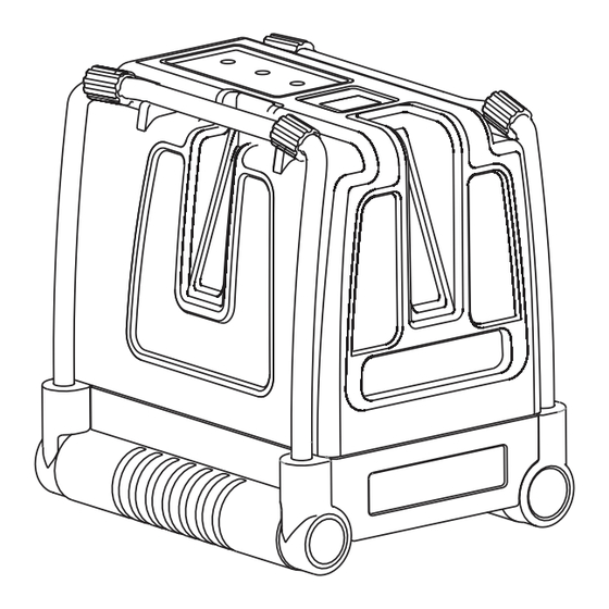
  • Page 61 VUE D'ENSEMBLE 1. Interrupteur On/Off 2. Pieds métalliques 3. Gaine caoutchouc de stabilité 4. Bloc de touches a. Bouton de mode manuel d. Témoin LED de mode manuel b. Bouton de sélection de faisceau e. Témoin LED de faisceau laser c.
  • Page 62 UTILISATION Fonctionnement en mode automatique (auto-nivellement) : En mode automatique, le niveau laser s'auto-nivelle lui- même dans une plage de ± 5° et projette horizontalement, verticalement ou les trois faisceaux simultanément. 1. Retirez le laser du boîtier de protection et placez-le sur une surface plane et sans vibration ou sur un trépied. 2.
  • Page 63 Utilisation en mode manuel En mode manuel, le mécanisme d'auto-nivellement du 872 est désengagé et les lignes laser peuvent être définies sur n'importe quelle inclinaison. 1. Appuyez sur le bouton de mode Manuel . Le laser projette les lignes croisées et le témoin LED rouge en regard du bouton s'illumine.Le témoin LED vert du faisceau laser en regard du bouton V/H s'illumine.
  • Page 64 Utilisation en mode impulsion avec un détecteur Lorsque l'appareil est utilisé directement exposé au soleil ou dans des conditions lumineuses élevées, ou à l'intérieur jusqu'à une portée de 60 mètres, utilisez le mode impulsion avec un détecteur. Lorsque le mode impulsion est engagé, les lignes laser clignotent à fréquence très élevée (invisibles à l'œil nu), ce qui permet au détecteur de détecter les lignes laser. 1. Le mode impulsion peut être engagé en mode automatique et manuel. 2. Pour passer en mode impulsion, appuyez sur le bouton P, le témoin LED vert en regard du bouton P s'illumine.
  • Page 65 ENTRETIEN Afin de garantir la précision de votre projet, vérifier l'exactitude de votre niveau laser en utilisant les procédures d'étalonnage sur le terrain. • Changez les piles lorsque l'intensité des faisceaux laser faiblit. • Nettoyez la fenêtre de projection et le boîtier du niveau laser à l'aide d'un chiffon propre et doux. N'utilisez pas de solvants. • Bien que le niveau laser soit résistant à l'eau et à la poussière, ne le remisez pas en un endroit poussiéreux, une longue exposition étant susceptible d'endommager des pièces mobiles internes.
  • Page 66 TEST D'ÉTALONNAGE SUR SITE Le niveau laser quitte l'usine entièrement étalonné. Kapro recommande de vérifier régulièrement le niveau, et impérativement après une chute ou une erreur de manipulation. Pour ce faire, il est nécessaire de vérifier, dans l'ordre, la précision de hauteur de la ligne horizontale, la précision de nivellement de la ligne horizontale, et enfin la précision de nivellement de la ligne verticale. Vérification de la précision de hauteur de la ligne horizontale (écart haut/bas)
  • Page 67 5) Tournez le laser de 180° vers le mur B, et marquez sur le mur le centre des lignes croisées, comme point b1 (voir illustration 2). 180° illustration 2 Figure # 2 6) Déplacez le niveau laser face au mur B, à environ 50 cm du mur.
  • Page 68 8) Tournez le laser de 180° en direction du mur A, et marquez sur le mur le croisement des lignes comme point a2 (voir illustration 4). 180° illustration 4 Figure # 4 9) Mesurez les distances : Δa= |a2-a1| Δb= |b1-b2| 10) La différence | Δa – Δb| doit être inférieure à 2 mm, dans le cas contraire, le niveau laser doit être examiné par un technicien agréé.
  • Page 69 3) Marquez le point a1 sur le mur, à l'extrémité gauche de la ligne horizontale (voir illustration 5). 1.5m Figure # 5 illustration 5 4) Tournez le niveau laser dans le sens antihoraire jusqu'à ce que l'extrémité droite de la ligne horizontale soit au niveau de a1, et marquez le point a2 sur le mur, sur la ligne horizontale (voir illustration 6). x a1 x a2 illustration 6 Figure # 6...
  • Page 70 5) La distance entre a1 et a2 ne doit pas excéder 1 mm. Dans le cas contraire, le niveau laser doit être examiné par un technicien agréé. Vérification de la précision de la ligne verticale 1) Suspendez à un mur un fil à plomb d'environ 4 mètres. 2) Une fois le fil à plomb en équilibre, marquez le point a1 sur le mur derrière le fil à plomb, à côté du plomb (voir illustration 7). Figure # 7 illustration 7 3) Placez le laser sur un trépied ou une surface solide, face au...
  • Page 71 6) Sur le mur, marquez le point a2 au milieu de la ligne verticale et à la même hauteur que a1 (voir illustration 8). illustration 8 Figure # 8 7) La distance entre a1 et a2 ne doit pas excéder 1 mm, dans le cas contraire, le niveau laser doit être examiné par un technicien agréé.
  • Page 72 4. Vérification de l'exactitude de l'orthogonalité entre les deux faisceaux verticaux. Pour cette opération, il est nécessaire de disposer d'une pièce d'au moins 5 m x 5 m avec 4 murs. 1) Placez le laser sur une table ou sur le sol au milieu de la pièce. 2) Déverrouillez le balancier et appuyez 4 fois sur le bouton V/H pour projeter les faisceaux verticaux avant et latéral (voir illustration 9).
  • Page 73 3) Marquez le centre du faisceau vertical avant en 2 endroits, le point a1 sur la table près du laser, et le point a2 sur le mur A. 4) Maquez le centre du faisceau vertical latéral en 2 endroits, le point b1 sur la table près du laser, et le point b2 sur le mur B. (voir illustration 10). # ‫תמונה‬ illustration 10 Figure # 10...
  • Page 74 5) faites pivoter le laser dans le sens horaire afin que le faisceau laser traverse la marque b1 sur la table et la marque b2 sur le mur B. 6) Maquez le centre du faisceau vertical latéral en 2 endroits, le point c1 sur la table près du laser, et le point c2 sur le mur C (voir illustration 11). illustration 11 Figure # 11...
  • Page 75 7) faites pivoter le laser dans le sens horaire afin que le faisceau laser traverse la marque c1 sur la table et la marque c2 sur le mur C. 8) Maquez le centre du faisceau vertical latéral en 2 endroits, le point d1 sur la table près du laser, et le point d2 sur le mur D (voir illustration 12). illustration 12 Figure # 12...
  • Page 76 9) faites pivoter le laser dans le sens horaire afin que le faisceau laser traverse la marque d1 sur la table et la marque d2 sur le mur D. 10) Maquez le centre du faisceau vertical latéral en 2 endroits, le point a3 sur la table près du point a1, et le point a4 sur le mur A près du point a2. (voir illustration 13). a2 X X a4 d2 X illustration 13 Figure # 13 11) Mesurez les distances : Δ1 = distance entre a1 et a3...
  • Page 77 CARACTÉRISTIQUES Sorties faisceaux Faisceau horizontal et deux faisceaux verticaux laser orthogonaux Faisceaux horizontal et vertical avant Faisceau horizontal Faisceau vertical avant Verticales orthogonales avant et latérale Portée laser • Intérieur 30 m (100 ft) • Extérieur avec détecteur650 m (200 ft) Précision ±0.2mm/m (±0.0002in/in) Angle ventilateur...
  • Page 78 Cette garantie ne couvre pas les produits utilisés de façon inappropriée, modifiés ou réparés sans le consentement de Kapro. En cas de problème avec votre niveau laser, veuillez ramener le produit au lieu d'achat avec la preuve d'achat. Modèle n° 873G Prolaser Vector ®...
  • Page 80 Компания Kapro благодарит вас за выбор 873 GREEN Prolaser Vector. Теперь вам принадлежит один из самых ® передовых из существующих лазерных инструментов. Это руководство поможет вам эксплуатировать инструмент с максимальной эффективностью. ОБЛАСТИ ПРИМЕНЕНИЯ Инновационный лазерный уровень 873 GREEN Prolaser ®...
  • Page 81 СОДЕРЖАНИЕ Функции • Техника безопасности 83-84 • Установка батарей и безопасность 85-86 • Общий вид • Инструкция по эксплуатации 88-90 • Обслуживание • Полевая проверка калибровки 92-102 • Технические характеристики • Гарантия •...
  • Page 82 ФУНКЦИИ • Этот лазерный инструмент автоматически выравнивается по горизонтальной и вертикальной плоскостям. • Лазерный уровень проецирует 1 горизонтальную и 2 взаимно перпендикулярные вертикальные зеленые линии с пересечениями впереди и на потолке. • Автоматическое самовыравнивание в пределах диапазона самовыравнивания. • Визуальный и звуковой сигнал для положения вне диапазона...
  • Page 83 ТЕХНИКА БЕЗОПАСНОСТИ ПРЕДУПРЕЖДЕНИЕ Этот прибор является источником излучения, которое относится к Классу II в соответствии со стандартом EN 60825 -1 Лазерное излучение может привести к серьезным повреждениям глаз • Не допускайте попадания лазерного луча в глаза • Не устанавливайте лазерный уровень так, чтобы он...
  • Page 84 ЗАМЕТКА Зеленые очки предназначены для повышения видимость лазерного луча. Они не защитят ваши глаза от лазерного излучения. • Не удаляйте и не искажайте предупреждающие надписи на лазерном уровне. • Не разбирайте лазерный уровень, лазерное излучение может привести к серьезным повреждениям глаз. •...
  • Page 85 УСТАНОВКА БАТАРЕЙ И БЕЗОПАСНОСТЬ 1. Нажмите на защелку и снимите крышку батарейного отсека. 2. Вставьте 3 новые батарейки формата АА одной марки в соответствие со схемой полярности на внутренней части батарейного отсека. 3. Установите крышку отсека на место. ЗАМЕТКА Если лазерный уровень не...
  • Page 86 Батареи могут портиться, ПРЕДУПРЕЖДЕНИЕ: протекать или вздуваться, что может привести к травмам или пожару. 1. Не закорачивайте клеммы батарей. 2. Не заряжайте щелочные батареи не предназначенные для повторной зарядки. 3. Не следует смешивать старые и новые батареи. 4. Не выбрасывайте батареи с бытовым мусором. 5.
  • Page 87 ОБЩИЙ ВИД 1. Выключатель 2. Металлические ножки 3. Резиновая муфта 4. Клавиатура a. Ручной режим b. Переключатель режимов работы c. Импульсный режим d. Индикатор ручного режима e. Индикатор лазерного луча f. Индикатор импульсного режима 5. Окно горизонтального лазера 6. Окно переднего вертикального лазера 7.
  • Page 88 ИНСТРУКЦИЯ ПО ЭКСПЛУАТАЦИИ Работа в автоматическом режиме (самовыравнивание): В автоматическом режиме лазерный уровень самовыравнивается в диапазоне ± 5 ° и может проецировать горизонтальную или одну/две вертикальные линии или все три линии одновременно. 1. Извлеките лазер из чехла и поместите его на твердую плоскую...
  • Page 89 ИИ Работа в ручном режиме: В ручном режиме механизм самовыравнивания отключен и лазерные линии могут быть установлены под любом требуемым углом. 1. Нажмите кнопку "Ручной режим" . Лазерный уровень начнёт проецировать перекрещенные линии, красный индикатор рядом загорится, также загорится зеленый с...
  • Page 90 Работа в импульсном режиме с детектором: Для наружных работ под прямым солнечным светом или в условиях яркого освещения а также для увеличения рабочей дистанции в помещении до 60 метров, используйте импульсный режим с детектором. При активированном импульсном режиме проецируемые лазерные линии мигают с очень высокой частотой (неуловимой...
  • Page 91 ОБСЛУЖИВАНИЕ Для сохранения точности в вашей работе, регулярно проверяйте калибровку вашего лазерного уровня в соответствии с процедурой проверки калибровки в полевых условиях. • Замените батареи, если лазерные лучи начинают тускнеть. • Очищайте окошки лазеров и корпус уровня чистой мягкой тканью. Не используйте растворители. •...
  • Page 92 ПОЛЕВАЯ ПРОВЕРКА КАЛИБРОВКИ Завод-изготовитель поставляет лазерные уровни в полностью откалиброванном виде. Компания Kapro рекомендует проверять уровень на регулярной основе, а также после каждого падения или нарушения правил эксплуатации инструмента. Для этого необходимо сначала проверить калибровку горизонтальной линии по высоте, затем проверить точность выравнивания горизонтальной...
  • Page 93 КИ 5) Поверните лазер на 180° в сторону стены B и отметьте на ней точку пересечения линий как b1 (см. рис. № 2). ла 180° й е. ися рисунок № 2 Figure # 2 А 6) Переместите лазерный уровень и установите его примерно...
  • Page 94 8) Разверните уровень на 180° в сторону стены А и отметьте на стене А точку пересечения линий как а2 (см. рис. № 4). 180° рисунок № 4 Figure # 4 9) Измерьте расстояния: Δa = | a2-a1 | Δb = | b1-b2 | 10) Разность| Δa - Δb | не...
  • Page 95 ьте 3) Отметьте точку a1 на стене на левом конце горизонтальной линии (см. рис. № 5). 1,5м 1.5m рисунок № 5 Figure # 5 4) Разверните лазерный уровень против часовой стрелки так, чтобы правый конец горизонтальной линии оказался вблизи точки a1, отметьте точку а2 на стене (см. рис. № 6). x a1 x a2 и.
  • Page 96 5) Расстояние по вертикали между точками a1 и a2, не должно превышать 1 мм, в противном случае отправьте лазерный уровень квалифицированному технику на калибровку. Проверка точности вертикальной линии. 1) Подвесить отвес приблизительно 4 метра длинной вплотную к стене. 2) После того, как отвес стабилизируется, отметьте точку a1 на...
  • Page 97 6) Отметьте точку а2 на стене на той же высоте, что и a1. е (см. рис. № 8). 2м Figure # 8 рисунок № 8 ть 7) Расстояние по горизонтали между a1 и a2, не должно превышать 1мм, в противном случае отправьте лазерный уровень...
  • Page 98 4. Проверка точности угла 90º между 2-мя вертикальными линиями. Для этой проверки требуется помещение размерами по крайней мере 5х5 метров с 4-мя стенами. 1) Установите прибор на столе или на полу в центре помещения. 2) Разблокируйте маятник и нажмите кнопку V/H 4 раза, чтобы...
  • Page 99 3) Сделайте отметки на передней вертикальной линии в 2-х местах: точка a1 на столе возле прибора и точка а2 на стене А. 4) Сделайте отметки на боковой вертикальной линии в 2-х местах: точка b1 на столе возле прибора и точка b2 на...
  • Page 100 5) Поверните прибор по часовой стрелке так, чтобы передняя вертикальная линия прошла через отметки b1 на столе, и b2 на стене B. 6) Сделайте отметки на боковой линии в 2-х местах: точка c1 на столе возле прибора и точка c2 на стене С. (см.
  • Page 101 7) Поверните прибор по часовой стрелке так, чтобы чтобы передняя вертикальная линия прошла через отметки c1 на столе, и с2 на стене C. 8) Сделайте отметки на боковой линии в 2-х местах: точка d1 на столе возле прибора и точка d2 на стене D. (см.
  • Page 102 8) Поверните прибор по часовой стрелке так, чтобы чтобы передняя вертикальная линия прошла через отметки d1 на столе и d2 на стене D. 9) Сделайте отметки на боковой линии в 2-х местах: точка a3 на столе вблизи точки а1 и точка a4 на стене А вблизи точки...
  • Page 103 ТЕХНИЧЕСКИЕ ХАРАКТЕРИСТИКИ Проецируемые лазерные Горизонтальная и 2 вертикальные линии линии Горизонтальная и вертикальная линии Горизонтальная линия Передняя вертикальная линия Передняя и боковая вертикальные линии Максимальная дальность • В помещении: 30 м • Вне помещения: 60 м (с приемником) Погрешность 0,2 мм/м (0.0002in/in) Угол...
  • Page 104 ГАРАНТИЯ На изделие распространяется двухлетняя гарантия отсутствия дефектов материалов и изготовления. Нарушения правил эксплуатации, изменения конструкции или самостоятельный ремонт приводят к аннулированию гарантии. При появлении проблем с приобретенным лазерным уровнем, верните его в место покупки, приложив подтверждение покупки. Модель: № 873G Prolaser Vector ®...
  • Page 105 1 05...
  • Page 106 © 2017 Kapro Industries Ltd. 1 06...