
Manuels Connexes pour Kapro CROSSLIGHT 3D LASER GREEN


Sommaire des Matières pour Kapro CROSSLIGHT 3D LASER GREEN
- Page 1 CROSSLIGHT™ 3D LASER GREEN Model No. 863G User Manual Manual del usuario Manuel d'utilisation Руководство по эксплуатации 2 x 18650 RECHARGEABLE Up to 60m/200'...
- Page 2 Thank you for purchasing Kapro’s 863G Crosslight™ 3D Laser. You now own one of the most advanced laser tools available. This manual will show you how to get the most out of your laser tool. APPLICATIONS The 863G Crosslight™ 3D Laser is a laser level with 3 green diodes, that emit 3 circular lines.
- Page 3 CONTENTS • Features • Safety instructions • Battery installation & Safety • Overview • Operating instructions 10-11 • Maintenance • Field calibration test 13-22 • Specifications • Warranty 24-25...
- Page 4 FEATURES • This laser tool automatically determines the horizontal and vertical planes. • This laser emits 1 horizontal 360° and 2 orthogonal 360° vertical green beams, that intersect on 4 walls, floor and ceiling. • Self-leveling in automatic mode when the laser is positioned within its self-leveling range which is ±4º...
- Page 5 SAFETY INSTRUCTIONS WARNING This product emits radiation classified as Class II according to EN 60825 -1 The laser radiation can cause serious eye injury • Do not stare into the laser beam. • Do not position the laser beam so that it unintentionally blinds you or others. •...
- Page 6 • Do not remove or deface warning labels on the laser level. • Do not disassemble the laser level, as laser radiation can cause serious eye injury. • Do not drop the unit. • Do not use solvents to clean the laser unit. •...
- Page 7 BATTERY INSTALLATION & SAFETY The 863G Crosslight™ 3D Laser uses 2 rechargeable 18650 Lithium batteries. Installation 1. Press down the latch of the battery cover. 2. Insert the two 18650 batteries according to the polarity marks on the lid of the battery compartment. 3.
- Page 8 Charge the 18650 batteries when the charge indicator (d) start blinking. Use only the charger provided by the manufacturer. WARNING : Batteries can deteriorate, leak or explode and can cause injury or fire. 1. Do not shorten the battery terminals. 2.
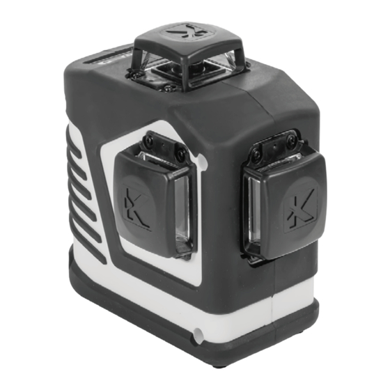
- Page 9 OVERVIEW 1. On/Off Locking Switch 2. Keypad a. Beam Selector Button b. Manual Mode Button c. Pulse Mode Button d. Battery LED indicator 3. Horizontal Laser Beam 4. Front Vertical Laser Beam 5. Side Vertical Laser Beam 6. Battery Cover 7.
- Page 10 OPERATING INSTRUCTIONS Working in Automatic mode (self-leveling): In automatic mode the laser level will level itself within a ± 4° range and will project 1 horizontal 360° and/or 2 vertical 360° green beams. 1. Remove the laser level from the case and place it on a solid, flat, vibration free surface or on a tripod.
- Page 11 Manual mode In Manual mode the out-of-level warning of 863G Crosslight™ 3D Laser is disabled and the laser level can be set at any slope. 1. Remove the laser level from the case and place it on a solid, flat, vibration free surface or on a tripod. 2.
- Page 12 MAINTENANCE To maintain the accuracy of your project, check the accuracy of your laser level according to the field calibration tests procedures. • Charge the battery when the laser beams begin to dim. • Wipe the aperture lens and the body of the laser level with a clean, soft cloth.
- Page 13 FIELD CALIBRATION TEST This laser level left the factory fully calibrated. Kapro recommends the user check the accuracy of the laser periodically, especially if the unit falls or is mishandled. 1. Check the height accuracy of the cross created by the front vertical and the horizontal lines.
- Page 14 approximately 5 m Figure # 1 0.5 m 6) Rotate the laser 180°. Reposition the laser and verify that the 2 vertical lines pass through a1 and c1. 7) Mark on wall B the the intersection point of the beams as b1 (see figure # 2).
- Page 15 8) Without turning the laser level, lock the pendulum and move the laser level towards wall B and position it approximately 0.5 meter from wall B. 9) Turn on the pendulum to project all 3 lasers beams. 10) Verify that the vertical line passes through a1 and b1. 11) On wall B, mark the intersection point of the beams as b2 (see figure # 3).
- Page 16 180° Figure # 4 0.5 m 14) Measure the distances: Δa= |a2-a1| Δb= |b1-b2| 15) The difference | Δa – Δb| should be no more than 3 mm, otherwise send the laser level to a qualified technician for repair.
- Page 17 2. Checking the height accuracy of the cross created by the front vertical and horizontal lines. (Up and down deviation) 1) Set up the laser on a table or on the floor between 3 walls A, B and C. The distance between A and B should be approximately 5 meters.
- Page 18 a1 x Figure # 5 3) Set up the laser on a tripod or on a solid surface in front of the wall, at a distance of approximately 2 meters. 4) Turn on the device and select the front vertical beam alone. Project it on the plumb line.
- Page 19 Figure # 6 7) The distance between a1 and a2, should be no more than 1mm, otherwise send the laser level to a qualified technician for repair. 4. Checking the Accuracy of the side vertical beam. For the second vertical beam, repeat the previous marking procedures from steps 1-7.
- Page 20 5. Checking 90º accuracy between the 2 vertical beams. This procedure requires a room of at least 5x5 meters with 3 walls. 1) Set up the laser on a table or on the floor in the middle of the room. 2) Turn on the laser and press beam selector button to project the front and the side vertical beams.
- Page 21 2.5m 2.5m Figure # 7 5) Rotate the laser 90° counterclockwise so that the intersection point pass through c1 on the table, and the side laser beam passes through the marks a1 and b1 on the walls A and B respectively. 6) Mark as c3 the center of the side vertical beam on wall C, at the same height as point c2.
- Page 22 2.5m 2.5m Figure # 8 7) The distance between c2 and c3, should be no more than 1.5mm, otherwise send the laser level to a qualified technician for repair.
- Page 23 SPECIFICATIONS Laser beams output • Horizontal and Verticals beams all 360° pattern • Horizontal beam 360° • Side Vertical beam 360° • Horizontal and Side Vertical beam 360° • Side and Front Vertical beams 360° Laser range • Indoor -30m (100ft) •...
- Page 24 This product is covered by a two year limited warranty against defects in materials and workmanship. The warranty does not cover products that are used improperly, altered, or repaired without Kapro's approval, nor a process of recalibration if needed. REPAIR AND CALIBRATION PROCEDURE 1.
- Page 25 CE CONFORMITY CERTIFICATE This product meets the standards of the Electromagnetic Compatibility (EMC) established by the European Directive 2014/30/EU and the Low Voltage Directive (LVD) 2014/35/EU EC DECLARATION OF CONFORMITY We declare under our responsibility that the product 863G is in accordance with the requirements of the Community Directives and Regulations: 2014/30/EU...
- Page 26 Gracias por comprar el 863G Crosslight™ 3D Laser de Kapro, una de las herramientas láser más avanzadas del mercado. Este manual le mostrará cómo sacarle el máximo partido. APLICACIONES El 863G Crosslight™ 3D Láser es un nivel láser con 3 diodos verdes, que emite 3 líneas circulares.
- Page 27 ÍNDICE • Características • Instrucciones de seguridad 29-30 • Instalación de pilas y seguridad 31-32 • Descripción general • Instrucciones de funcionamiento 34-36 • Mantenimiento • Prueba de calibración 37-46 • Especificaciones • Garantía 48-49...
- Page 28 CARACTERÍSTICAS • Esta herramienta láser determina automáticamente los planos horizontal y vertical. • Este láser emite 1 rayo horizontal 360° y 2 rayos ortogonales verticales verdes 360°, que se intersecan en 4 paredes, piso y cielorraso. • Auto-nivelación en modo automático cuando el láser está posicionado dentro de su rango de auto-nivelación, que es ±4°...
- Page 29 INSTRUCCIONES DE SEGURIDAD ADVERTENCIA Este producto emite radiación clasificada como de Clase II según la norma EN 60825 -1 La radiación láser puede causar lesiones oculares graves • No mire directamente al rayo láser • No posicione el haz de láser de modo que enceguezca sin querer a otras personas o a usted mismo.
- Page 30 • No quite ni destruya las etiquetas de advertencia del nivel láser. • No desarme el nivel láser, la radiación láser puede causar lesiones oculares graves. • No deje caer la unidad. • No utilice disolventes para limpiar la unidad láser. •...
- Page 31 INSTALACIÓN DE PILAS Y SEGURIDAD El Láser 863G Crosslight™ 3D usa 2 baterías 18650 recargables. Instalación 1. Presione el pestillo de la tapa de las baterías. 2. Introduzca las dos baterías 18650 según las marcas de polaridad en la tapa del compartimiento de baterías. 3.
- Page 32 Cargue las baterías 18650, usando el cargador incluido, cuando se encienda el indicador de batería baja (d). ADVERTENCIA: Las pilas pueden deteriorarse, producir fugas o explosiones, y pueden causar lesiones o incendios. 1. No acorte los terminales de las pilas. 2.
- Page 33 DESCRIPCIÓN GENERAL 1. Interruptor de bloqueo On/Off (encendido/apagado) 2. Teclado a. Botón selector de rayos b. Botón de modo manual c. Botón de modo de pulsos d. Indicador LED de baterías 3. Rayo láser horizontal 4. Rayo láser frontal vertical 5.
- Page 34 INSTRUCCIONES DE FUNCIONAMIENTO Trabajo en modo Automático (auto-nivelación): En modo automático, el nivel láser se auto-nivelará en el rango de ± 4°, y proyectará 1 rayo verde 360° horizontal y/o 2 rayos verdes 360° verticales. 1. Retire el nivel láser del estuche y colóquelo sobre una superficie sólida, plana y libre de vibraciones, o sobre un trípode.
- Page 35 Modo manual En modo manual, la advertencia de ‘fuera de nivel’ del Láser 863G Crosslight™ 3D está desactivada, y se puede establecer el nivel láser en cualquier pendiente. 1. Retire el nivel láser del estuche y colóquelo sobre una superficie sólida, plana y libre de vibraciones, o sobre un trípode. 2.
- Page 36 MANTENIMIENTO Para mantener la exactitud de su proyecto, verifique la precisión de su nivel láser de acuerdo con los procedimientos de pruebas de calibración de campo. • Cambie las baterías cuando los rayos láser comiencen a atenuarse. Limpie el lente de apertura y el cuerpo del nivel láser con un paño suave y limpio.
- Page 37 PRUEBA DE CALIBRACIÓN Este nivel láser sale de fábrica totalmente calibrado. Kapro recomienda al usuario comprobar la precisión del láser periódicamente, especialmente en caso de caída de la unidad o manipulación indebida. 1. Compruebe la precisión de la altura de la intersección de las líneas laterales (n.º...
- Page 38 aproximadamente 5 m 0.5 m Figura #1 6) Gire el láser 180° hacia la pared B. Vuelva a colocar el láser y verifique que las 2 líneas verticales pasan por a1 y c1. 7) Marque en la pared B el centro del punto de intersección como b1 (véase la figura n.º...
- Page 39 8) Sin girar el nivel láser, bloquee el péndulo y mueva el nivel hacia la pared B. Colóquelo aproximadamente a 0,5 metros de la pared B. 9) Desbloquee el péndulo y presione el botón (a) dos veces para proyectar los 3 rayos láser. 10) Verifique que la línea vertical pase por a1 y b1.
- Page 40 180° 0.5 m Figura #4 14) Mida las distancias: Δa= |a2-a1| Δb= |b1-b2| 15) La diferencia | Δa – Δb| no debe ser superior a 3 mm. De lo contrario, el nivel láser debe ser reparado por un técnico calificado.
- Page 41 2. Comprobación de la precisión de la altura de la intersección de las líneas longitudinales (n.º 4) y la línea horizontal. (Desviación hacia arriba y hacia abajo). 1) Coloque el láser sobre una mesa o en el suelo entre 3 paredes A, B y C.
- Page 42 a1 x Figura #5 3) Coloque el láser sobre un trípode o sobre una superficie llana, delante de la pared a una distancia de aproximadamente 2 metros. 4) Desbloquee el péndulo y pulse el botón para proyectar el rayo vertical frontal (n.º 4) hacia la línea de plomada. 5) Gire el láser de modo que el rayo vertical se fusione con la línea de plomada por debajo del punto de suspensión.
- Page 43 Figura #6 7) La distancia entre a1 y a2 no debe ser superior a 1 mm. De lo contrario, el nivel láser debe ser reparado por un técnico calificado. 4. Comprobación de la precisión rayo vertical lateral (n.º 5). Para el segundo rayo vertical, repita el procedimiento de marcación indicado anteriormente en los puntos 1 a 7.
- Page 44 5. Comprobación de la precisión de 90º entre los 2 rayos verticales. Este procedimiento debe realizarse en una sala de al menos 5 x 5 metros con 3 paredes. 1) Coloque el láser sobre una mesa o sobre el suelo en el centro de la sala.
- Page 45 2.5m 2.5m Figura #7 5) Gire el láser 90° en sentido contrario a las agujas del reloj para que los rayos transversales pasen a través de c1 sobre la mesa, y el rayo frontal pase a través de las marcas a1, y b1 sobre las paredes A y B, respectivamente.
- Page 46 2.5m 2.5m Figura #8 7) La distancia entre c2 y c3 no debe ser superior a 1,5 mm. De lo contrario, el nivel láser debe ser reparado por un técnico calificado.
- Page 47 ESPECIFICACIONES Patrón de salida de rayos Horizontal y Vertical 360° láser Horizontal 360° Vertical Laterial 360° Horizontal y Vertical Lateral 360° Lateral y Frontal Vertical 360° Rango del láser • En interiores – 30 m (100 ft) • Con detector – 60 m (200 ft) Precisión ±0.3mm/m (±0.0003in/in) Intervalo de...
- Page 48 La garantía no cubre productos que sean utilizados de forma inapropiada, alterados o reparados sin la aprobación de Kapro, ni un proceso de recalibración en caso de ser necesario. PROCEDIMIENTO DE REPARACIÓN Y CALIBRACIÓN 1.
- Page 49 CERTIFICADO DE CONFORMIDAD CE Este producto cumple con las normas de Compatibilidad Electromagnética (CEM) establecido por la Directiva Europea 2014/30/EU y el Reglamento para baja tensión 2014/35/EU. DECLARACIÓN DE CONFORMIDAD CE Declaramos bajo nuestra responsabilidad, que el producto: 863G está en acuerdo con los requisitos de las directivas y reglamentos siguientes: 2014/30/EU 2011/65/EU...
- Page 50 Nous vous remercions d'avoir acheté le laser 3D 863G Crosslight™ de Kapro. Vous possédez maintenant l'un des outils laser les plus avancés du marché. Ce manuel décrit comment tirer le meilleur parti de votre outil laser. APPLICATIONS Le laser 3D 863G Crosslight™ est un niveau laser à 3 diodes vertes, qui émet 3 lignes circulaires.
- Page 51 CONTENU • Fonctions • Consignes de sécurité 53-54 • Installation des piles et sécurité 55-56 • Vue d'ensemble • Utilisation 58-59 • Entretien • Test d'étalonnage 61-70 • Caractéristiques • Garantie 72-73...
- Page 52 FONCTIONS • Cet outil laser calcule automatiquement les plans horizontal et vertical. • Ce laser émet 1 faisceau verte horizontal de 360° et 2 faisceaux vertes verticaux orthogonaux de 360°, qui se croisent sur 4 murs, le sol et le plafond. •...
- Page 53 CONSIGNES DE SÉCURITÉ ATTENTION Ce produit émet un rayonnement de classe 2 selon la norme EN 60825 -1 Le rayonnement laser peut entraîner de graves lésions oculaires • Ne pas regarder dans le faisceau laser • Ne pas placer le faisceau laser de sorte qu'il pointe en direction de vos yeux ou des yeux d'autrui •...
- Page 54 • N’enlevez pas et n’abîmez pas les étiquettes d'avertissement du niveau laser. • Ne démontez pas le niveau laser, le rayonnement laser peut provoquer de graves lésions oculaires. • Ne laissez pas tomber le dispositif. • N'utilisez pas de solvants pour nettoyer le dispositif laser. •...
- Page 55 INSTALLATION DES PILES ET SÉCURITÉ Le laser 3D 863G Crosslight™ utilise 2 piles rechargeables de 18650. Installation 1. Appuyez sur le loquet du couvercle des piles. 2. Insérez les deux piles 18650 en respectant les marques de polarité sur le couvercle du compartiment des piles. 3.
- Page 56 Chargez les piles 18650 à l'aide du chargeur fourni lorsque le voyant de charge faible (d) s'allume. ATTENTION: Les piles peuvent se détériorer, fuir ou exploser et ainsi causer des blessures ou des incendies. 1. Ne raccourcissez pas les bornes des piles. 2.
- Page 57 VUE D'ENSEMBLE 1. Interrupteur de verrouillage marche/arrêt 2. Clavier a. Bouton de sélection de faisceau b. Bouton de mode manuel c. Bouton de mode pulsé d. Voyant LED de batterie 3. Faisceau laser horizontal 4. Faisceau laser vertical avant 5. Faisceau laser vertical latéral 6.
- Page 58 UTILISATION Travailler en mode automatique (auto-nivellement) : En mode automatique, le niveau laser se met à niveau dans une plage de ± 4 ° et projette un faisceau horizontal de 360 ° et/ou deux faisceaux verts verticaux de 360 °. 1.
- Page 59 Mode manuel : En mode manuel, l'avertissement de dépassement de niveau du laser 3D 863G Crosslight™ est désactivé et les faisceaux laser peuvent être réglés sur n'importe quelle inclinaison souhaitée. 1. Retirez le niveau laser du boîtier et placez-le sur une surface solide, plane et sans vibration ou sur un trépied.
- Page 60 ENTRETIEN Pour maintenir la précision de votre projet, vérifiez la précision de votre niveau laser selon les procédures de tests d'étalonnage sur le terrain. • Chargez les piles dès que les faisceaux laser commencent à s'affaiblir. • Essuyez la lentille d'ouverture et l’ensemble du niveau laser avec un chiffon doux et propre.
- Page 61 TEST D'ÉTALONNAGE Le niveau laser quitte l'usine étalonné. Kapro recommande que le niveau soit vérifié régulièrement, ou lorsque l'appareil subit une chute ou une mauvaise manipulation. 1. Vérifiez la précision verticale de la croix créée par les lignes horizontale (n°5) et latérale.
- Page 62 5 mètres environ 0.5 m illustration 1 6) Tournez le laser de 180° vers le mur B. Repositionnez-le et vérifiez que les deux lignes verticales passent par les points a1 et c1. 7) Marquez comme point b1 le croisement des lignes sur le mur B. (voir illustration 2).
- Page 63 8) Sans tourner le niveau laser. Verrouillez le balancier et orientez le niveau laser en direction du mur B, à environ 0.5 m du mur. 9) Déverrouillez le balancier et appuyez deux fois sur le buton de faisceau (a) pour projeter les trois faisceaux laser. 10) Vérifiez que la ligne verticale passe par a1 et b1.
- Page 64 180° 0.5 m illustration 4 14) Mesurez les distances : Δa= |a2-a1| Δb= |b1-b2| 15) La différence (Δa - Δb) doit être inférieure à 3 mm. Dans le cas contraire, le niveau laser doit être examiné par un technicien agréé.
- Page 65 2. Vérification de la précision verticale de la croix créée par les lignes longitudinale (n°4) et horizontale. (écart haut/bas) 1) Placez le laser sur une table ou au sol entre trois murs A, B et C. La distance entre A et B doit être d'environ 5 mètres. 2) Positionnez le niveau laser à...
- Page 66 a1 x illustration 5 3) Placez le laser sur un trépied ou une surface solide, face au mur, à une distance d'environ 2 mètres. 4) Déverrouillez le balancier et appuyez sur le bouton pour projeter le faisceau vertical frontal (n°4) en direction du fil à plomb.
- Page 67 illustration 6 7) La distance entre a1 et a2 doit être inférieure à 1mm. Dans le cas contraire, le niveau laser doit être examiné par un technicien agréé. 4. Vérification de la précision du faisceau vertical latéral (n°5) Pour le second faisceau vertical, répétez les opérations de marquage 1 à...
- Page 68 5. Vérification de l'orthogonalité entre les deux faisceaux verticaux Pour cette opération, il est nécessaire de disposer d'une pièce d'au moins 5 m x 5 m avec 3 murs. 1) Placez le laser sur une table ou sur le sol au milieu de la pièce.
- Page 69 2.5m 2.5m illustration 7 5) Tournez le laser de 90° dans le sens antihoraire afin que les faisceaux croisés passent par c1 sur la table, et que le faisceau laser avant passe par les marques a1 et b1 sur les murs A et B.
- Page 70 2.5m 2.5m illustration 8 7) La distance entre c2 et c3 doit être inférieure à 1,5mm. Dans le cas contraire, le niveau laser doit être examiné par un technicien agréé.
- Page 71 CARACTÉRISTIQUES Caractéristiques • Horizontal et vertical de 360° des faisceaux laser • Horizontal de 360° • Vertical Latéral de 360° • Horizontal et Vertical Latéral de 360° • Latéral et Vertical Avant de 360° Portée laser • Intérieur :30 m (100ft) •...
- Page 72 La garantie ne couvre pas les produits utilisés de façon incorrecte, modifiés ou réparés sans l'approbation de Kapro, ni une procédure d’étalonnage si celle-ci s’avère nécessaire. PROCÉDURE DE RÉPARATION ET D'ÉTALONNAGE 1.
- Page 73 CERTIFICAT DE CONFORMITÉ CE Ce produit est conforme aux normes de compatibilité électromagnétique (CEM) établi par la directive européenne 2014/30/EU et le règlement pour basse tension 2014/35/EU. DÉCLARATION DE CONFORMITÉ CE Nous déclarons sous notre responsabilité que le produit: 863G est conforme aux exigences et réglementations suivantes : 2014/30/EU 2011/65/EU...
- Page 74 Компания Kapro благодарит вас за выбор 863G Crosslight™. Теперь вам принадлежит один из самых передовых из существующих лазерных инструментов. Это руководство поможет вам эксплуатировать инструмент с максимальной эффективностью. ОБЛАСТИ ПРИМЕНЕНИЯ Лазерный уровень 3D 863G Crosslight™ оснащен тремя диодами зеленого цвета, которые проецируют три круговые...
- Page 75 СОДЕРЖАНИЕ Функции • Техника безопасности 77-78 • Установка батарей и безопасность 79-80 • Общий вид • Инструкция по эксплуатации 82-83 • Обслуживание • Полевая проверка калибровки 85-94 • Технические характеристики • Гарантия 96-97 •...
- Page 76 ФУНКЦИИ • Данный лазерный уровень автоматически определяет горизонтальную и вертикальную плоскости. • Лазер излучает одну горизонтальную и две вертикальные зеленые круговые линии (все по 360°), которые перекрещиваются под прямым углом на четырех стенах, полу и потолке. • Самовыравнивание в автоматическом режиме в диапазоне ± 4°. •...
- Page 77 ТЕХНИКА БЕЗОПАСНОСТИ ПРЕДУПРЕЖДЕНИЕ Этот прибор является источником излучения, которое я относится к Классу II в соответствии со стандартом EN 60825 -1 Лазерное излучение может привести к а серьезным повреждениям глаз • Не допускайте попадания лазерного луча в глаза • Не устанавливайте лазерный уровень так, чтобы он...
- Page 78 • Не удаляйте и не искажайте предупреждающие надписи на лазерном уровне. • Не разбирайте лазерный уровень, лазерное излучение может привести к серьезным повреждениям глаз. • Не роняйте лазерный уровень. • Не используйте растворители для очистки лазерного уровня. • Не используйте при температуре ниже -10° C или выше 50° C •...
- Page 79 УСТАНОВКА БАТАРЕЙ И БЕЗОПАСНОСТЬ В лазерном уровне 863G Crosslight™ 3D используются два аккумулятора 18650. УСТАНОВКА 1. Нажмите защелку на крышке аккумуляторного отсека. 2. Вставьте два аккумулятора 18650, соблюдая полярность, указанную на крышке аккумуляторного отсека. 3. Закройте крышку.
- Page 80 Если загорается индикатор низкого заряда (d), аккумуляторы 18650 необходимо зарядить. Батареи могут портиться, ПРЕДУПРЕЖДЕНИЕ: протекать или вздуваться, что может привести к травмам или пожару. 1. Не закорачивайте клеммы батарей. 2. Не заряжайте щелочные батареи не предназначенные для повторной зарядки. 3. Не следует смешивать старые и новые батареи. 4.
- Page 81 ОБЩИЙ ВИД 1. Выключатель с фиксатором 2. Клавиатура a. Кнопка выбора луча b. Кнопка ручного режима c. Кнопка импульсного режима d. Светодиодный индикатор батареи 3. Горизонтальный лазерный луч 4. Передний вертикальный лазерный луч 5. Боковой вертикальный лазерный луч 6. Крышка отсека батареи 7.
- Page 82 ИНСТРУКЦИЯ ПО ЭКСПЛУАТАЦИИ Работа в автоматическом режиме (самовыравнивание): В автоматическом режиме лазерный уровень выполняет автоматическое выравнивание с допуском ± 4° и будет излучать 1 горизонтальный луч на 360° и/или 2 вертикальных зеленых луча на 360°. 1. Извлеките лазерный уровень из кейса и поместите его на прочную, плоскую, не...
- Page 83 Ручной режим: В ручном режиме предупреждение о выходе за пределы уровня лазерного прибора 863G Crosslight™ 3D Laser отключено, и лазерный нивелир можно установить под любым углом наклона. 1. Извлеките лазерный уровень из кейса и поместите его на прочную, плоскую, не вибрирующую поверхность или на...
- Page 84 ОБСЛУЖИВАНИЕ Чтобы обеспечить точность выполнения работы, проверяйте точность лазерного уровня согласно инструкциям по процедуре полевых калибровочных испытаний. • Заряжайте аккумуляторы, когда лазерные лучи начинают тускнеть. • Протирайте апертурные линзы и корпус уровня сухой мягкой тканью. Не используйте растворители. • Несмотря на то, что лазерный уровень является в определенной...
- Page 85 ПОЛЕВАЯ ПРОВЕРКА КАЛИБРОВКИ Завод-изготовитель поставляет лазерные уровни в полностью откалиброванном виде. Компания Kapro рекомендует проверять уровень на регулярной основе, а также после каждого падения или нарушения правил эксплуатации инструмента. 1. Проверьте точность расположения точки пересечения горизонтальной линии с боковой вертикальной линией...
- Page 86 3) Разблокируйте маятник и нажатиями на кнопку Выбор луча (a) выберите проекцию всех трёх лазерных линий. 4) Направьте точку пересечения горизонтальной и боковой вертикальной линий на стену А. 5) Отметьте на стене А точку пересечения линий как а1, на стене С отметьте точку пересечения горизонтальной и...
- Page 87 6) Разверните прибор на 180° по направлению к стене B. Установите прибор так, чтобы 2 вертикальные линии проходили через точки a1 и c1. 7) Отметьте на стене В точку пересечения линий как b1 (См. рис. № 2). 180° 2м рисунок № 2 0,5м...
- Page 88 2м 0,5м 0.5 m рисунок № 3 12) Разверните прибор на 180°. Переставьте лазер так, чтобы вертикальная линия проходила через точки b2 и a1. 13) Отметьте на стене А точку пересечения линий как a2. (См. рис. №4). 180° 2м 0,5м 0.5 m рисунок...
- Page 89 2. Проверка точности расположения по высоте точки пересечения горизонтальной линии с передней вертикальной линией. 1) Установите прибор на столе или на полу между тремя стенами - A, B и C. Расстояние между стенами А и В должны быть приблизительно 5 метров. 2) Установите...
- Page 90 a1 x рисунок № 5 3) Установите лазерный уровень на штатив или другую устойчивую поверхность на расстоянии около 2 метров перед стеной. 4) Разблокируйте маятник и выберите проекцию переднего вертикального лазера (# 4) по направлению к линии отвеса. 5) Поверните прибор так, чтобы вертикальная лазерная линия...
- Page 91 2м рисунок № 6 7) Расстояние между a1 и a2 по горизонтали не должно превышать 1 мм, в противном случае следует послать лазерный уровень к квалифицированному специалисту для ремонта. 4. Проверка точности выравнивания передней вертикальной линии (#5). Для проверки второй вертикальной линии повторите пункты...
- Page 92 5. Проверка точности прямого угла между вертикальными линиями. Для этой проверки потребуется помещение размерами по крайней мере 5х5 метров с 3-мя стенами. 1) Установите прибор на столе или на полу в середине помещения. 2) Разблокируйте маятник и нажатиями на кнопку Выбор луча...
- Page 93 5м 2.5м 2.5м 2.5m 2.5m рисунок № 7 5) Поверните лазер на 90° против часовой стрелки и совместите точку пересечения проекций вертикальных лазеров с точкой c1 на столе, проекция переднего вертикального лазера должна проходить через точки a1 и b1 на стенах А и В соответственно. 6) Отметьте...
- Page 94 5м 2.5м 2.5m 2.5м 2.5m рисунок № 8 7) Расстояние по горизонтали между точками с2 и с3, не должно превышать 1,5 мм, в противном случае следует послать лазерный уровень к квалифицированному специалисту для ремонта.
- Page 95 ТЕХНИЧЕСКИЕ ХАРАКТЕРИСТИКИ Проецируемые • Горизонтальная и вертикальная 360° лазерные линии • Горизонтальная 360° • Боковая вертикальная 360° • Горизонтальная Боковая вертикальная 360° • Боковая и вертикальная 360° передняя Максимальная • 30м в помещении дальность • до 60м с детектором Погрешность 0,3 мм/м...
- Page 96 материальных дефектов сроком на два года. В случае использования изделия ненадлежащим образом, а также внесения в него конструкционных изменений или ремонта без разрешения компании Kapro, гарантия аннулируется. Кроме того, гарантия не распространяется на процесс повторной калибровки, если таковой необходим. РЕМОНТ И КАЛИБРОВКА...
- Page 97 СЕРТИФИКАТ СООТВЕТСТВИЯ СЕ Этот продукт соответствует стандартам Электромагнитной Совместимости (CEM) установленным Европейской директивой 2014/30/EU и Регламентом для устройств низкого напряжения 2014/35/EU. ДЕКЛАРАЦИЯ О СООТВЕТСТВИИ Мы заявляем под нашу ответственность, что устройство 863G соответствует требованиям следующих директив и правил Европейского Сообщества: 2014/30/EU 2011/65/EU EN60825-1: 2014...
- Page 100 Rev. 4.0 © 2023 Kapro Industries Ltd. 1 00...