Télécharger Imprimer la page

Publicité

Les langues disponibles

Les langues disponibles

Liens rapides

ATTACH YOUR RECEIPT HERE
Serial Number _____________________________ Purchase Date ______________________
Questions, problems, missing parts? Before returning to your retailer, call our customer
service department at 1-877-447-4768, 8:30 a.m. – 4:30 p.m., CST, Monday – Friday
or e-mail us at customerservice@ghpgroupinc.com.
PREMIER GAS GRILL
Model #DGP397SNP / DGP397SNP-D /
DGP397CNP / DGP397CNP-D / DGP397GNP /
DGP397GNP-D / DGP397MNP/DGP397MNP-D
1
3 BURNER
Français p. 32
XX
Français p.
XX
Español p. 63
Español p.
Rev. 03/05/2019

Publicité

loading

Sommaire des Matières pour Dyna-Glo DGP397SNP

  • Page 1 3 BURNER PREMIER GAS GRILL Model #DGP397SNP / DGP397SNP-D / DGP397CNP / DGP397CNP-D / DGP397GNP / DGP397GNP-D / DGP397MNP/DGP397MNP-D Français p. 32 Français p. Español p. 63 Español p. ATTACH YOUR RECEIPT HERE Serial Number _____________________________ Purchase Date ______________________ Questions, problems, missing parts? Before returning to your retailer, call our customer service department at 1-877-447-4768, 8:30 a.m.
  • Page 2 TABLE OF CONTENTS Safety Information ........................3 Package Contents ........................5 Hardware Contents ........................6 Preparation ..........................6 Assembly Instructions ........................ 7 Operation Instructions ......................... 18 Care and Maintenance ......................... 23 Troubleshooting ........................... 26 Warranty ............................28 Replacement Parts List ......................29 Assembler/Installer: This manual contains important information necessary for the proper assembly and safe use of this appliance.
  • Page 3 SAFETY INFORMATION Please read and understand this entire manual before attempting to assemble, operate or install the product. If you have any questions regarding the product, please call customer service at: 1-877-447-4768, 8:30 a.m. – 4:30 p.m., CST, Monday – Friday. DANGER •...
  • Page 4 SAFETY INFORMATION WARNING • Do not place the grill under overhead combustible construction or awnings. Minimum clearance from sides and 36in back of unit to combustible construction, 36in 914.4mm 36 inches (914.4mm) from sides and 914.4mm back. NOTE: The installation must conform with local codes or, in the absence of local codes, with either the National Fuel Gas Code, ANSI Z223.1/NFPA 54, Natural...
  • Page 5 PACKAGE CONTENTS PART DESCRIPTION QUANTITY PART DESCRIPTION QUANTITY Hood Handle Door Assembly Temp Gauge Door Handle Grill Body Assembly Left Side Shelf Assembly Side Shelf Bracket A Heat Tent Right Side Shelf Assembly Cooking Grate Side Shelf Bracket B Warming Rack Cart Right Side Panel Assembly Control Knob Locking Swivel Caster...
  • Page 6 HARDWARE CONTENTS M6x16 M6x16 M6x35 M6x35 M3x10 M3x10 M6x16 M6x35 M3x10 M6x16 M3x10 M6x16 M6x35 M6x35 M3x10 M6x16 M6x35 M3x10 M6x16 M6x35 M3x10 M3x10 M6x16 M6x16 M6x35 M6x35 M3x10 Bolt Bolt Washer Washer Spring Spring Wing Nut Wing Nut Bolt Bolt Bolt Bolt...
  • Page 7 ASSEMBLY INSTRUCTIONS Attach the two locking swivel casters (H) and the two non-locking swivel casters (I) to the cart left side panel assembly (L) and the cart right side panel assembly (G) with wrench (II). Hardware Used Wrench Attach the cart left side panel assembly (L) and the cart right side panel assembly (G) to the cart bottom panel shelf (J) with four M6x16 bolts (AA).
  • Page 8 ASSEMBLY INSTRUCTIONS Attach the bottom panel skirt assembly (K) to the cart left side panel assembly (L) and the cart right side panel assembly (G) with two M6x16 bolts (AA). Tighten ALL bolts from step 2 securely. Hardware Used M6x16 Bolt Attach the cart rear panel (W) to the cart left side panel assembly (L) and the cart right side panel assembly (G) with the four M6x16 bolts...
  • Page 9 ASSEMBLY INSTRUCTIONS Attach the upper front door brace (V) to the cart left side panel assembly (L) and the cart right side panel assembly (G) with four M6x35 bolts (EE). Hardware Used M6x35 Bolt M6x35 M3x10 Wing Nut Bolt Bolt Washer Spring Washer...
  • Page 10 ASSEMBLY INSTRUCTIONS Attach the door handle (N) to the door assembly (M) with two M6x16 bolts (AA). Hardware Used M6x16 Bolt Hardware Used M6x16 Bolt Insert the bottom hinge pin of the cart bottom panel skirt (K) into the lower hole on the door assembly (M), then press the upper door spring hinge pin into the hole on the upper front door brace (V) as shown.
  • Page 11 ASSEMBLY INSTRUCTIONS Attach the hood handle (A) to the grill body Hardware Used assembly (C) with two M6 wing nuts (DD), M6 Washer two M6 spring washers (CC) and two M6 plain washers (BB). Spring Washer M6 Wing Nut Hardware Used M6 Plain Washer M6 Spring Washer M6x16...
  • Page 12 ASSEMBLY INSTRUCTIONS Carefully place the grill body (C) onto cart left side panel assembly (L) and cart right side panel assembly (G). Adjust the grill body (C) so that the holes in the grill body (C) are aligned with holes in the tabs of cart left side panel as- sembly (L) and cart right side panel assembly (G).
  • Page 13 ASSEMBLY INSTRUCTIONS Attach the side shelf bracket A (D) and side shelf bracket B (F) to the grill body assembly (C) with eight M6x12 flat bolts (GG). Hardware Used M6x12 Flat Bolt...
  • Page 14 ASSEMBLY INSTRUCTIONS Attach the left side shelf assembly (O) to the brackets installed at step 13 with two shoulder bolts (HH). Repeat it for right side shelf assembly (E). Hardware Used Shoulder Bolt...
  • Page 15 ASSEMBLY INSTRUCTIONS Put three heat tents (P) in place over each burner. Put two cooking grates (Q) and one warming rack (R) in place.
  • Page 16 ASSEMBLY INSTRUCTIONS Put the grease pan (T) and grease cup (U) into place. Assemble the three control knobs (S) to the valve stems.
  • Page 17 ASSEMBLY INSTRUCTIONS Open the door assembly (M). Place LP gas cylinder (sold separately) into the nesting hole located on the cart bottom shelf (J). Rotate the LP gas cylinder until the hose/ regulator coupling aligns with the threaded valve of the cylinder. Hand tighten the hose/ regulator coupling to the threaded valve of the LP gas cylinder.
  • Page 18 OPERATION INSTRUCTIONS CHECKING FOR LEAKS After all connections are made, check all connections and fittings on the LP gas tank valve, gas hose and regulator for leaks with a water and soap solution. To prevent fire or explosion while testing for a leak: •...
  • Page 19 OPERATION INSTRUCTIONS CONNECTING GAS CYLINDER The propane gas supply cylinder to be used must be constructed and marked in accordance with the Specifications for LP Gas Cylinders of the U.S. Department of Transportation (D.O.T.) or the National Standard of Canada, CAN/CSA-B339, Cylinders, Spheres and Tubes for Transportation of Dangerous Goods;...
  • Page 20 OPERATION INSTRUCTIONS NOTE: Other cylinders may be acceptable for use with this appliance provided they are compatible with the appliance nesting hole and retention means. Refer to Step 19 of the Assembly Instructions for correct cylinder to cylinder holder connection. WARNING ALL INSTRUCTIONS AND SAFEGUARDS ON THIS PAGE MUST BE FOLLOWED TO PREVENT FIRE, DAMAGE AND/OR INJURY.
  • Page 21 OPERATION INSTRUCTIONS Lighting The Grill Before first use: Remove all hangings or plastic straps, if present. Before you cook on your new gas grill, it is important to clean your grill with heat. To do this, operate the grill for approximately 15 minutes with the lid closed and the control knob in the highest position.
  • Page 22 OPERATION INSTRUCTIONS LIGHTING THE GRILL WITH A MATCH 1. Open the lid. 2. Insert a match in the end of the match holder that is installed on the inside of the cabinet door. 3. Light the match. 4. Immediately place the lit match through the spaces in the grill gates near the ports of the burner between the heat tents as shown.
  • Page 23 CARE AND MAINTENANCE Cooking Grates The best time to ‘burn-off’ the cooking grates is after every use (approx. 15 minutes). The grill is already hot from cooking thus requiring less fuel to obtain necessary temperature for ‘burn-off’. To ‘burn off’ or heat clean your grill, turn the burners to highest position and run for 15 minutes with the lid closed.
  • Page 24 CARE AND MAINTENANCE Burner Assembly Warming Removing The Burner Assembly Rack Cooking Grates 1. Make sure all control knobs are in the OFF position, gas supply valve is closed, and the Heat Tents gas hose is disconnected from the gas supply. 2.
  • Page 25 CARE AND MAINTENANCE Cleaning the Burner Assembly – Make sure the grill is cool 1. Ensure all burner ports are clear of clogs. Use of a pin or paper clip works well. 2. Ensure burner is free of any damage. If damage is found, replace with new burner. 3.
  • Page 26 TROUBLESHOOTING If you have any questions regarding the product, please call customer service at 1-877-447-4768, 8:30 a.m. – 4:30 p.m., CST, Monday – Friday. PROBLEM POSSIBLE CAUSE CORRECTIVE ACTION The burner will not 1. The igniter electrode may be 1. Clean the ignitor electrode. light using the covered with grease or residue.
  • Page 27 TROUBLESHOOTING PROBLEM POSSIBLE CAUSE CORRECTIVE ACTION The burner will not 1. Match not reaching burners 1. Use match holder found in light with a match. (when holding match with cabinet door. hand). 2. Check fuel level and refill tank if 2.
  • Page 28 GHP Group Inc. 6440 W. Howard Street Niles, IL, USA 60714-3302 Item Name: 3 Burner Premier Gas Grill Model #: DGP397SNP / DGP397SNP-D / DGP397CNP / DGP397CNP-D / DGP397GNP / DGP397GNP-D / DGP397MNP / DGP397MNP-D Main burner total rated BTU: 36,000 BTU/Hr...
  • Page 29 REPLACEMENT PARTS LIST For replacement parts, call our customer service department at 1-877-447-4768, 8:30 a.m. – 4:30 p.m., CST, Monday – Friday. 28 29...
  • Page 30 Main valves and manifold assembly 70-01-950 Corrugated hose assembly 70-01-885 Connector 70-01-886 Control Panel - DGP397SNP-D / DGP397SNP, DGP397GNP-D / DGP397GNP, DGP397MNP-D / 70-01-953 DGP397MNP - Stainless Control Panel - DGP397CNP-D / DGP397CNP - Black 70-01-954 Control knob bezel 70-01-184...
  • Page 31 REPLACEMENT PARTS LIST For replacement parts, call our customer service department at 1-877-447-4768, 8:30 a.m. – 4:30 p.m., CST, Monday – Friday. PART DESCRIPTION PART # Cart right rear leg tube 70-01-958 Match holder with chain 70-01-846 Cart Bottom Panel Shelf 70-01-895 Cart rear panel 70-01-896...
  • Page 32 BARBECUE AU PROPANE DE PREMIÈRE QUALITÉ À TROIS BRÛLEURS Nᵒ de modèle DGP397SNP / DGP397SNP-D / DGP397CNP / DGP397CNP-D / DGP397GNP / DGP397GNP-D/DGP397MNP / DGP397MNP-D English p. 1 Français p. Español p. 63 Español p. AGRAFEZ VOTRE FACTURE ICI Numéro de série _____________________________ Date d’achat ______________________ Questions, problèmes, pièces manquantes? Avant de retourner l’article au détaillant,...
  • Page 33 TABLE DES MATIÈRES Informations relatives à la sécurité ..................... 34 Contenu de l’emballage ......................36 Quincaillerie fournie ........................37 Préparation ..........................37 Instructions d’assemblage ......................38 Instructions de fonctionnement ....................49 Entretien et maintenance ......................54 Dépannage ..........................57 Garantie ............................59 Liste des pièces de rechange ....................
  • Page 34 INFORMATIONS RELATIVES À LA SÉCURITÉ Veuillez lire et comprendre le présent guide avant de tenter d’assembler, d’utiliser ou d’installer le produit. Si vous avez des questions concernant le produit, veuillez appeler le service à la clientèle au : 1 877 447-4768, entre 8 h 30 et 16 h 30 (HNC), du lundi au vendredi. DANGER •...
  • Page 35 INFORMATIONS RELATIVES À LA SÉCURITÉ AVERTISSEMENT • Ne placez pas le barbecue sous des constructions inflammables ou des auvents. Le dégagement minimum entre l’appareil, sur 36 po les côtés et à l’arrière, et les constructions 36 po 914,4mm inflammables est de 36 po (914,4 mm). 914,4mm R EMARQUE : L’installation doit être conforme aux codes locaux ou, en l’absence de codes locaux, au...
  • Page 36 CONTENU DE L’EMBALLAGE PIÈCE DESCRIPTION QUANTITÉ PIÈCE DESCRIPTION QUANTITÉ Poignée du couvercle Porte Jauge de température Poignée de porte Bâti du barbecue Tablette latérale gauche Support de tablette latérale A Plaque de rayonnement Tablette latérale droite Grille de cuisson Support de tablette latérale B Grille d’attente Panneau droit du chariot Bouton de commande...
  • Page 37 QUINCAILLERIE FOURNIE M6x16 M6x16 M6x35 M6x35 M3x10 M3x10 M6x16 M6x35 M3x10 M6x16 M3x10 M6x16 M6x35 M6x35 M3x10 M6x16 M6x35 M3x10 M6x16 M6x35 M3x10 M3x10 Boulon Rondelle M6x16 Rondelle Écrou à Boulon M6x35 Boulon Bolt Bolt Washer Washer Spring Spring Wing Nut Wing Nut Bolt Bolt...
  • Page 38 INSTRUCTIONS D’ASSEMBLAGE Fixez les deux roulettes à blocage (H) et les deux roulettes sans blocage (I) au panneau gauche (L) et au panneau droit (G) du chariot à l’aide de la clé (II). Matériel utilisé Clé Fixez le panneau gauche (L) et le panneau droit (G) du chariot à...
  • Page 39 INSTRUCTIONS D’ASSEMBLAGE Fixez la jupe du panneau inférieur (K) au panneau gauche (L) et au panneau droit (G) du chariot avec deux boulons M6 x 16 mm (AA). Serrez fermement TOUS les boulons de l’étape 2. Matériel utilisé Boulon M6 x 16 mm Fixez le panneau arrière du chariot (W) au panneau gauche (L) et au panneau droit (G) du chariot avec quatre boulons M6 x 16 mm (AA).
  • Page 40 INSTRUCTIONS D’ASSEMBLAGE Fixez le support supérieur de porte (V) au panneau gauche (L) et au panneau droit (G) du chariot avec quatre boulons M6 x 35 mm (EE). Matériel utilisé Boulon M6 x 35 mm M6x35 M3x10 Wing Nut Bolt Bolt Washer Spring...
  • Page 41 INSTRUCTIONS D’ASSEMBLAGE Fixez la poignée de porte (N) à la porte (M) à l’aide de deux boulons M6 x 16 mm (AA). Hardware Used M6x16 Bolt Matériel utilisé Boulon M6 x 16 mm Insérez l’axe de charnière inférieur de la jupe du panneau inférieur (K) du chariot dans le trou inférieur de la porte (M), puis insérez l’axe de charnière supérieur à...
  • Page 42 INSTRUCTIONS D’ASSEMBLAGE Fixez la poignée du couvercle (A) au bâti du Hardware Used barbecue (C) avec deux écrous à oreilles M6 M6 Washer (DD), deux rondelles élastiques M6 (CC) et deux rondelles plates M6 (BB). Spring Washer M6 Wing Nut Matériel utilisé...
  • Page 43 INSTRUCTIONS D’ASSEMBLAGE Placez doucement le bâti du barbecue (C) sur le panneau gauche (L) et le panneau droit (G) du chariot. Ajustez le bâti du barbecue (C) pour que ses trous soient alignés avec ceux des languettes du panneau gauche (L) et du panneau droit (G) du chariot.
  • Page 44 INSTRUCTIONS D’ASSEMBLAGE Fixez le support de tablette latérale A (D) et le support de tablette latérale B (F) au bâti du barbecue (C) avec huit boulons plats M6 x 12 mm (GG). Matériel utilisé Boulon plat M6 x 12 mm...
  • Page 45 INSTRUCTIONS D’ASSEMBLAGE Fixez la tablette latérale gauche (O) aux supports installés à l’étape 13 avec deux boulons à épaulement (HH). Répétez cette étape pour la tablette latérale droite (E). Matériel utilisé Boulon à épaulement...
  • Page 46 INSTRUCTIONS D’ASSEMBLAGE Placez les trois plaques de rayonnement (P) sur chaque brûleur. Placez les deux grilles de cuisson (Q) et la grille d’attente (R).
  • Page 47 INSTRUCTIONS D’ASSEMBLAGE Placez le plateau à graisse (T) ainsi que le récupérateur de graisse (U). Assemblez les trois boutons de commande (S) aux tiges de la vanne.
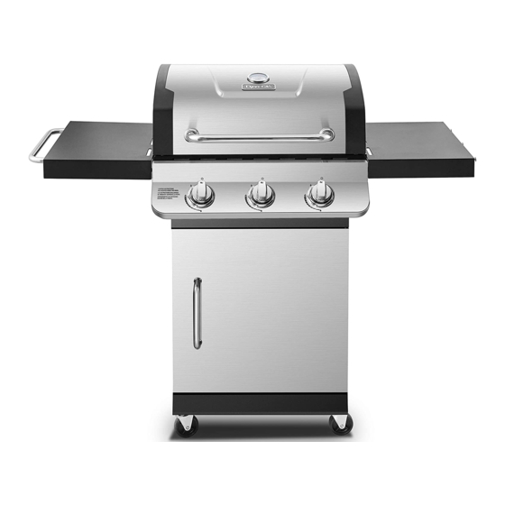
  • Page 48 INSTRUCTIONS D’ASSEMBLAGE Ouvrez la porte (M). Placez la bouteille de propane liquide (vendue séparément) dans le range-bouteille situé sur la tablette inférieure du chariot (J). Tournez la bouteille de propane liquide jusqu’à ce que le raccord du tuyau/régulateur soit aligné avec la vanne filetée de la bouteille.
  • Page 49 INSTRUCTIONS DE FONCTIONNEMENT DÉCELER DES FUITES DE GAZ Lorsque tous les raccordements sont effectués, vérifiez qu’il n’y a aucune fuite à la vanne de la bouteille de propane liquide, au tuyau de propane et au régulateur à l’aide d’une solution d’eau savonneuse.
  • Page 50 INSTRUCTIONS DE FONCTIONNEMENT BRANCHER LA BOUTEILLE DE PROPANE La bouteille de propane doit être fabriquée et identifiée selon les spécifications sur les bouteilles à gaz du département des Transports des États-Unis (DOT) ou selon la norme CAN/CSA-B339 intitulée « Bouteilles à gaz cylindriques et sphériques et tubes pour le transport des marchandises dangereuses »...
  • Page 51 INSTRUCTIONS DE FONCTIONNEMENT REMARQUE : D’autres bouteilles peuvent être utilisées avec cet appareil, pourvu qu’elles soient compatibles avec le range-bouteille et le système de retenue. Consultez l’étape 19 des instructions d’assemblage pour savoir comment connecter correctement une bouteille à son support. AVERTISSEMENT TOUTES LES INSTRUCTIONS ET MESURES DE SÉCURITÉ...
  • Page 52 INSTRUCTIONS DE FONCTIONNEMENT Allumer le barbecue Avant la première utilisation : Retirez tous les emballages et toutes les attaches de plastique, le cas échéant. Avant de cuisiner sur votre nouveau barbecue au propane, il est important de le nettoyer avec de la chaleur. Pour ce faire, faites fonctionner le barbecue pendant environ 15 minutes avec le couvercle baissé...
  • Page 53 INSTRUCTIONS DE FONCTIONNEMENT ALLUMER LE BARBECUE AVEC UNE ALLUMETTE 1. Ouvrez le couvercle. 2. Insérez une allumette dans le porte-allumettes qui se trouve à l’intérieur de la porte du barbecue. 3. Allumez l’allumette. 4. Placez immédiatement l’allumette dans un des espaces des grilles du barbecue qui se trouvent près des orifices du brûleur, entre les plaques de rayonnement, comme illustré.
  • Page 54 ENTRETIEN ET MAINTENANCE Grilles de cuisson Le moment idéal pour brûler les résidus sur les grilles de cuisson est juste après leur utilisation, pendant environ 15 minutes. Puisque le barbecue est déjà chaud, atteindre la température voulue pour le nettoyage demande moins de combustible. Pour brûler les résidus, réglez le barbecue à...
  • Page 55 ENTRETIEN ET MAINTENANCE Brûleur Grille d’attente Retirer le brûleur Grilles de cuisson 1. Assurez-vous que tous les boutons de commande sont en position d’arrêt, que la Plaques de vanne d’alimentation en propane est fermée rayonnement et que le tuyau de propane est déconnecté de l’alimentation.
  • Page 56 ENTRETIEN ET MAINTENANCE Nettoyer le brûleur – Assurez-vous que le barbecue est froid. 1. Veillez à ce que tous les orifices du brûleur soient libres d’obstructions. Vous pouvez utiliser une broche ou un trombone. 2. Assurez-vous que le brûleur n’est pas endommagé. S’il l’est, remplacez-le. 3.
  • Page 57 DÉPANNAGE Si vous avez des questions concernant le produit, veuillez appeler le service à la clientèle au 1 877 447-4768, de 8 h 30 à 16 h 30 (HNC), du lundi au vendredi. PROBLÈME CAUSE POSSIBLE SOLUTION Le brûleur ne 1.
  • Page 58 DÉPANNAGE PROBLÈME CAUSE POSSIBLE SOLUTION Le brûleur ne 1. L’allumette n’atteint pas les 1. Utilisez le porte-allumettes qui se trouve s’allume pas avec brûleurs (lorsque vous la sur la porte du barbecue. une allumette. tenez avec votre main). 2. Bouteille vide. 2.
  • Page 59 GHP Group, Inc. 6440 W. Howard Street Niles, IL, États-Unis 60714-3302 Nom de l’article : Barbecue au propane de première qualité à trois brûleurs Nᵒ de modèle DGP397SNP/DGP397SNP-D/DGP397CNP/DGP397CNP-D/DGP397GNP/ DGP397GNP-D/DGP397MNP/DGP397MNP-D Puissance nominale en BTU du brûleur principal : 36 000 BTU/h...
  • Page 60 LISTE DES PIÈCES DE RECHANGE Pour des pièces de rechange, veuillez appeler le service à la clientèle au 1 877 447-4768, de 8 h 30 à 16 h 30 (HNC), du lundi au vendredi. 28 29...
  • Page 61 70-01-876 Soutien de la plaque de rayonnement du brûleur principal 70-01-833 Charnière du couvercle (avec écrou, rondelle et attache) 70-01-827 Couvercle – DGP397SNP-D/DGP397SNP – acier inoxydable 70-01-945 Couvercle – DGP397CNP-D/DGP397CNP – noir 70-01-946 Couvercle – DGP397GNP-D/DGP397GNP – bronze industriel 70-01-947 Couvercle –...
  • Page 62 LISTE DES PIÈCES DE RECHANGE Pour des pièces de rechange, veuillez appeler le service à la clientèle au 1 877 447-4768, de 8 h 30 à 16 h 30 (HNC), du lundi au vendredi. PIÈCE DESCRIPTION Nᵒ DE PIÈCE Tube du pied arrière droit du chariot 70-01-958 Porte-allumettes avec chaîne 70-01-846...
  • Page 63 PARRILLA PREMIER CON 3 QUEMADORES PARA GAS N.° de modelo DGP397SNP / DGP397SNP-D / DGP397CNP / DGP397CNP-D / DGP397GNP / DGP397GNP-D / DGP397MNP / DGP397MNP-D Français p. 32 Français p. Español p. 63 Español p. ADJUNTE SU RECIBO AQUÍ Número de serie _________________________ Fecha de compra ______________________ ¿Preguntas, problemas, piezas faltantes? Antes de hacer una devolución a la tienda,...
  • Page 64 CONTENIDO Información de seguridad ......................65 Contenido del paquete ........................ 67 Paquete de tornillería........................68 Preparación ..........................68 Instrucciones de ensamblaje ...................... 69 Instrucciones de funcionamiento ....................80 Cuidado y mantenimiento ......................85 Solución de problemas ........................ 88 Garantía ............................90 Lista de piezas de repuesto .......................
  • Page 65 INFORMACIÓN DE SEGURIDAD Lea y comprenda este manual por completo antes de intentar ensamblar, poner en funcionamiento o instalar el producto. Si tiene preguntas relacionadas con el producto, llame al Departamento de Atención al Cliente al 1-877-447-4768, de lunes a viernes de 8:30 a. m. a 4:30 p. m. (hora central estándar).
  • Page 66 INFORMACIÓN DE SEGURIDAD ADVERTENCIA • No coloque la parrilla debajo de toldos o estructuras combustibles. La distancia mínima desde los laterales y la parte trasera de la 36" unidad hasta una estructura combustible 36" 914,4 mm debe ser de 36" (914,4 mm). 914,4 mm N OTA: la instalación debe cumplir con los códigos locales o, en ausencia de códigos...
  • Page 67 CONTENIDO DEL PAQUETE PIEZA DESCRIPCIÓN CANTIDAD PIEZA DESCRIPCIÓN CANTIDAD Manija de la tapa Conjunto de la puerta Indicador de temperatura Manija de la puerta Conjunto del cuerpo de la parrilla Conjunto de la repisa lateral izquierda Abrazadera A de la repisa lateral Protector térmico Conjunto de la repisa lateral derecha Rejilla para cocinar...
  • Page 68 PAQUETE DE TORNILLERÍA M6x16 M6x16 M6x35 M6x35 M3x10 M3x10 M6x16 M6x35 M3x10 M6x16 M3x10 M6x16 M6x35 M6x35 M3x10 M6x16 M6x35 M3x10 M6x16 M6x35 M3x10 M3x10 Pernos Arandela M6x16 Arandela de Tuerca Pernos M6x35 Pernos Bolt Bolt Washer Washer Spring Spring Wing Nut Wing Nut Bolt...
  • Page 69 INSTRUCCIONES DE ENSAMBLAJE Fije las dos ruedecillas giratorias con mecanismo de bloqueo (H) y las dos ruedecillas giratorias sin mecanismo de bloqueo (I) al conjunto del panel del lateral izquierdo del carro (L) y el conjunto del panel del lateral derecho del carro (G) con la llave (II). Tornillería utilizada Llave Fije el conjunto del panel del lateral izquierdo del...
  • Page 70 INSTRUCCIONES DE ENSAMBLAJE Fije el conjunto del panel del borde inferior (K) al conjunto del panel del lateral izquierdo del carro (L) y al conjunto del panel del lateral derecho del carro (G) con dos pernos M6 × 16 (AA). Ajuste firmemente TODOS los pernos a partir del paso 2.
  • Page 71 INSTRUCCIONES DE ENSAMBLAJE Fije el tirante de la puerta de la parte frontal superior (V) al conjunto del panel del lateral izquierdo del carro (L) y al conjunto del panel del lateral derecho del carro (G) con cuatro pernos M6 × 35 (EE). Tornillería utilizada Pernos M6 ×...
  • Page 72 INSTRUCCIONES DE ENSAMBLAJE Fije la manija de la puerta (N) al conjunto de la puerta (M) con dos pernos M6 × 16 (AA). Hardware Used M6x16 Bolt Tornillería utilizada Pernos M6 × 16 × 2 Inserte el pasador de la bisagra inferior del panel del borde inferior del carro (K) en el orificio inferior del conjunto de la puerta (M), luego presione el resorte del pasador de la...
  • Page 73 INSTRUCCIONES DE ENSAMBLAJE Fije la manija de la tapa (A) al conjunto del Hardware Used cuerpo de la parrilla (C) con dos tuercas M6 Washer mariposa (DD), dos arandelas de resorte M6 (CC) y dos arandelas planas M6 (BB). Spring Washer M6 Wing Nut Tornillería utilizada Arandela plana M6...
  • Page 74 INSTRUCCIONES DE ENSAMBLAJE Ubique cuidadosamente el cuerpo de la parrilla (C) en el conjunto del panel del lateral izquierdo del carro (L) y el conjunto del panel del lateral derecho del carro (G). Ajuste el cuerpo de la parrilla (C) de manera que los orificios en el cuerpo de la parrilla (C) estén alineados con los orificios en las lengüetas del conjunto del panel del lateral izquierdo del carro (L) y del conjunto...
  • Page 75 INSTRUCCIONES DE ENSAMBLAJE Fije la abrazadera A de la repisa lateral (D) y la abrazadera B de la repisa lateral (F) al conjunto del cuerpo de la parrilla (C) con ocho pernos planos M6 x 12 (GG). Tornillería utilizada Pernos planos M6 x 12 ×...
  • Page 76 INSTRUCCIONES DE ENSAMBLAJE Fije el conjunto de la repisa lateral izquierda (O) a los soportes instalados en el paso 13 con dos pernos de tope (HH). Repita el proceso para el conjunto de la repisa lateral derecha (E). Tornillería utilizada Perno de tope ×...
  • Page 77 INSTRUCCIONES DE ENSAMBLAJE Coloque tres protectores térmicos (P) en su lugar sobre cada quemador. Coloque dos rejillas para cocinar (Q) y una rejilla para calentar (R) en su lugar.
  • Page 78 INSTRUCCIONES DE ENSAMBLAJE Ponga la grasera grande (T) y la grasera pequeña (U) en su lugar. Inserte las tres perillas de control (S) en los vástagos de la válvula.
  • Page 79 INSTRUCCIONES DE ENSAMBLAJE Abra el conjunto de la puerta (M). Ubique el tanque de gas propano líquido (se vende por separado) en el receptáculo ubicado en la repisa inferior del carro (J). Gire el tanque de gas propano líquido hasta que el acoplamiento de la manguera y el regulador se alinee con la válvula roscada del tanque.
  • Page 80 INSTRUCCIONES DE FUNCIONAMIENTO VERIFICACIÓN DE FUGAS Una vez que todas las conexiones estén listas, compruebe, con una solución de agua y jabón, que no haya fugas en ninguna de las conexiones y en ninguno de los ajustes en la válvula del tanque de gas de propano líquido, manguera de gas y regulador.
  • Page 81 INSTRUCCIONES DE FUNCIONAMIENTO CONECTAR EL TANQUE DE GAS El tanque para el suministro de gas propano que se vaya a utilizar debe estar fabricado y marcado de acuerdo con las especificaciones para los tanques de gas propano líquido del Departamento de Transporte de los Estados Unidos (D.O.T.) o con las normas nacionales de Canadá...
  • Page 82 INSTRUCCIONES DE FUNCIONAMIENTO NOTA: otros tanques podrían ser aceptados para su uso con este artefacto siempre y cuando sean compatibles con el receptáculo y sistema de fijación del artefacto. Consulte el paso 19 de las Instrucciones de ensamblaje para ver cómo es la conexión correcta entre el tanque y el soporte del tanque.
  • Page 83 INSTRUCCIONES DE FUNCIONAMIENTO Encender la parrilla Antes de utilizar la unidad por primera vez: Quite todas las presillas o las fajas de plástico, si están presentes. Es importante que limpie su nueva parrilla a gas con calor antes de utilizarla por primera vez. Para esto, ponga en funcionamiento la parrilla durante aproximadamente 15 minutos, con la tapa cerrada, y la perilla de control en la posición de llama máxima.
  • Page 84 INSTRUCCIONES DE FUNCIONAMIENTO ENCENDER LA PARRILLA CON UN FÓSFORO 1. Abra la tapa. 2. Inserte un fósforo en el extremo del portafósforo que está instalado dentro de la puerta del gabinete. 3. Encienda el fósforo. 4. Coloque inmediatamente el fósforo encendido en las rejillas de la parrilla, cerca de los puertos del quemador, entre los protectores térmicos, como se muestra en la figura.
  • Page 85 CUIDADO Y MANTENIMIENTO Rejillas para cocinar El mejor momento para limpiar con calor las rejillas de la parrilla es después de cada uso (aproximadamente 15 minutos). La parrilla ya está caliente luego de cocinar y, por lo tanto, requiere menos combustible para llegar a la temperatura necesaria para limpiar con calor. Para limpiar con calor su parrilla, lleve los quemadores a la posición de llama máxima y déjelos funcionar así...
  • Page 86 CUIDADO Y MANTENIMIENTO Conjunto del quemador Rejilla para Retirar el conjunto del quemador calentar Rejillas para cocinar 1. Asegúrese de que todas las perillas de control estén en la posición de APAGADO, la válvula de Protectores suministro de gas esté cerrada y la manguera de térmicos gas esté...
  • Page 87 CUIDADO Y MANTENIMIENTO Limpiar el conjunto del quemador – Asegúrese de que la parrilla esté fría. 1. Verifique que todos los puertos del quemador estén libres de obstrucciones. También funciona si usa un pasador o sujetapapeles. 2. Asegúrese de que el quemador esté libre de daños. Si encuentra algún daño, reemplácelo por uno nuevo. 3.
  • Page 88 SOLUCIÓN DE PROBLEMAS Si tiene alguna pregunta sobre el producto, llame al Departamento de Atención al Cliente al 1-877-447-4768, de lunes a viernes de 8:30 a. m. a 4:30 p. m. (hora central estándar). PROBLEMA CAUSA POSIBLE ACCIÓN CORRECTIVA El quemador no 1.
  • Page 89 SOLUCIÓN DE PROBLEMAS PROBLEMA CAUSA POSIBLE ACCIÓN CORRECTIVA El quemador no se 1. El fósforo no llega a los 1. Use el portafósforo que se encuentra en enciende con un quemadores (cuando sostiene la puerta del gabinete. fósforo. el fósforo con la mano). 2.
  • Page 90 Niles, IL, EE. UU. 60714-3302 Nombre del artículo: Parrilla premier con 3 quemadores para gas N.º de modelo: DGP397SNP / DGP397SNP-D / DGP397CNP / DGP397CNP-D / DGP397GNP / DGP397GNP-D / DGP397MNP / DGP397MNP-D Total nominal de BTU del quemador principal: 36,000 BTU/h...
  • Page 91 LISTA DE PIEZAS DE REPUESTO Para obtener las piezas de repuesto, llame a nuestro Departamento de Atención al Cliente al 1-877-447-4768, de lunes a viernes de 8:30 a. m. 4:30 p. m. (hora central estándar). 28 29...
  • Page 92 Soporte del quemador principal del protector térmico 70-01-833 Bisagra de la tapa (con tuerca, arandela y presilla) 70-01-827 Conjunto de la tapa - DGP397SNP-D / DGP397SNP - Inoxidable 70-01-945 Conjunto de la tapa - DGP397CNP-D / DGP397CNP - Negro 70-01-946 Conjunto de la tapa - DGP397GNP-D / DGP397GNP - Bronce de cañón...
  • Page 93 LISTA DE PIEZAS DE REPUESTO Para obtener las piezas de repuesto, llame a nuestro Departamento de Atención al Cliente al 1-877-447-4768, de lunes a viernes de 8:30 a. m. 4:30 p. m. (hora central estándar). PIEZA DESCRIPCIÓN N.º DE PIEZA Tubo de la pata trasera derecha del carro 70-01-958 Portafósforo con cadena...