Electrolux thermaline S90 Instructions D'installation Et D'emploi
Masquer les pouces
Voir aussi pour thermaline S90:
- Instructions d'installation et d'emploi (66 pages) ,
- Instructions d'installation (26 pages) ,
- Instructions d'installation et d'emploi (23 pages)
Table des Matières
Les langues disponibles
Les langues disponibles
Liens rapides
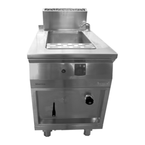
PASTA COOKER, GAS - PASTA COOKER POUR GAZ
US
INSTALLATION- AND OPERATING INSTRUCTIONS
FR
INSTRUCTIONS D'INSTALLATION ET D'EMPLOI
FOR YOUR SAFETY
Do not store or use gasoline or
other flammable vapors or liquids
in the vicinity of this or any other
appliance.
WARNING
Improper installation, adjust-
ment, alteration, service or
maintenance can cause property
damage, injury or death. Read the
installation, operating and
maintenance instructions thorou-
ghly before installing or servicing
this equipment.
INSTRUCTION
Post in a prominent location instructions to be followed if the user smells gas. Consult
the local gas supplier to obtain the information.
Présentez dans des instructions en avant d'un endroit d'être suivi si l'utilisateur sent le
gaz. Consultez le fournisseur local de gaz pour obtenir l'information.
thermaline S90
POUR VOTRE SÉCURITÉ
Ne déposez pas ou n'employez
pas l'essence ou d'autres vapeurs
ou liquides inflammables à pro-
ximité de ceci ou d'aucun autre
appareil.
AVERTISSEMENT
L'installation inexacte, l'ajuste-
ment, le changement, le service
ou l'entretien peuvent causer des
blessures matériels, des domma-
ges ou la mort. Lisez les instruc-
tions d'installation, d'opération et
d'entretien complètement avant
d'installer ou entretenir cet
équipement.
Doc.
62.9680.01_UL
Edition 1
01.2006
page 3
page 13
Table des Matières

Manuels Connexes pour Electrolux thermaline S90


Sommaire des Matières pour Electrolux thermaline S90
- Page 1 S90 PASTA COOKER, GAS - PASTA COOKER POUR GAZ Doc. 62.9680.01_UL Edition 1 01.2006 INSTALLATION- AND OPERATING INSTRUCTIONS page 3 INSTRUCTIONS D’INSTALLATION ET D’EMPLOI page 13 FOR YOUR SAFETY POUR VOTRE SÉCURITÉ Do not store or use gasoline or Ne déposez pas ou n'employez...
- Page 2 Against wall - contre une paroi Free standing - isolé Connections - Raccordement Gas - Gaz Fig.1 INSTALLATION DRAWINGS - PLANS D'INSTALLATION Doc. 62.9680.01_UL...
-
Page 15: Instructions Générales
INSTRUCTIONS GÉNÉRALES INSTRUCTIONS GÉNÉRALES CONSIGNES DE SÉCURITÉ ET D'UTILISATION TRAVAILLER EN TOUTE SÉCURITÉ INSTALLATION ET MISE EN SERVICE La plongée des paniers remplis d'aliments dans la cuve doit se faire lentement, de Le montage, le réglage et la première mise manière que l'eau chaude ne déborde pas. -
Page 16: Service-Après-Vente Et Réparation
INSTRUCTIONS GÉNÉRALES DONNÉES TECHNIQUES SERVICE-APRÈS-VENTE ET RÉPARATION Largeur Socle Super- Puissance Si un problème persistant empêche le Profondeur Pieds ficie Consommation Modèle de Appareil PNC fonctionnement correct de l'appareil, mettez- Hauteur Hauteur de gaz l'appareil le hors tension et débranchez-le. en mm en kW Pour toute opération d'entretien ou de répa-... -
Page 17: Instructions Relatives À L'installation
INSTRUCTIONS RELATIVES À L'INSTALLATION II . INSTRUCTIONS RELATIVES À L'INSTALLATION MISE EN PLACE ASSEMBLAGE DE DEUX APPAREILS Cet appareil est conçu pour être raccordé à des conduites fixes. Les appareils peuvent être montés individuellement ou en groupe. Ils peuvent être installés de façon indépendante, côte à... -
Page 18: Socle En Acier
INSTRUCTIONS RELATIVES À L'INSTALLATION PAROI LATERALE (D) ASSEMBLAGE SUR ROULETTES (3c) Fig.2 Montage du paroi latérale Chaque kit d'assemblage comprend respectivement deux vis hexagonales M8 x 25 (1 / Fig.1), des boulons avec circlip (2 (3c) (3c) / Fig.1), des éclisses (3 / Fig.1), des vis hexagonales M8 x 16 avec rondelles à... -
Page 19: Panneau De Commande (C)
INSTRUCTIONS RELATIVES À L'INSTALLATION PANNEAU AVANT (A) et (B) SORTIE (3c) Fig.6 Panneau avant Desserrez les vis (1 et 3, Fig.6). Si le four est encastré, desserrez Extrayez le panneau vers l'avant et le bas. PANNEAU DE COMMANDE (C) Fig.8 Sortie Les plans de travail avec sortie (fig. -
Page 20: Raccordement Au Gaz
INSTRUCTIONS RELATIVES À L'INSTALLATION RACCORDEMENT AU GAZ Resserrer la vis à fente dans la prise de mesure. Les écarts de tolérance de la pression de gaz sont stipulés Le raccordement au gaz, de même que la pose de la conduite dans l'EN 203. -
Page 21: Raccordement À L'eau Potable
INSTRUCTIONS RELATIVES À L'INSTALLATION RACCORDEMENT À L'ARRIVÉE D'EAU RACCORDEMENT À L'EAU POTABLE • Avant de raccorder l'appareil, nettoyez à fond les conduites d'eau et la robinetterie pour les débarrasser de toute impu- reté. • L'appareil est conçu pour être raccordé à des conduites fixes. -
Page 22: Instructions De Fonctionnement
INSTRUCTIONS DE FONCTIONNEMENT III . INSTRUCTIONS DE FONCTIONNEMENT GÉNÉRALITÉS ALLUMAGE DU DISPOSITIF D'ALLUMAGE Pasta Cooker sert à cuire des pâtes alimentaires de toute nature, du riz, des knödel, des boulettes, des légumes ainsi que des soupes. La température désirée peut être ajustée entre le °C 50 et 100. -
Page 23: Règles De Travail
INSTRUCTIONS DE FONCTIONNEMENT Avant chaque utilisation contrôler : Nettoyer les gicleurs de sortie à l'aide d'une brosse. Que le trop-plein (8) de la cuve ne soit pas bouché. Retirer le filtre sur le fond du bac d'eau (décrocher l'agrafe) et le nettoyer. Que les organes de commande ne soient pas endomma- gés À... - Page 24 INSTRUCTIONS DE FONCTIONNEMENT PROBLÈME Problème Cause Solution Le Pasta Cooker surch- • Niveau de l'eau trop - Remplissez avec de auffe; la puissance est bas. l'eau. trop faible. La flamme produit beau- • Le mélange gazeux est - Adressez-vous au Ser- coup de suie.