BFT MAXIMA ULTRA 68 Instructions D'utilisation Et D'installation
Masquer les pouces
Voir aussi pour MAXIMA ULTRA 68:
- Instructions d'installation et d'entretien (12 pages)
Table des Matières
Les langues disponibles
Les langues disponibles
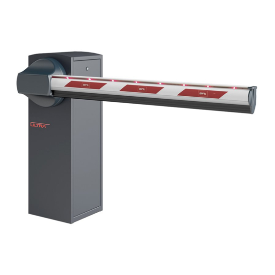
BARRIERA AUTOMATICA
AUTOMATIC BARRIER
BARRIÈRE AUTOMATIQUE
AUTOMATISCHE SCHRANKE
BARRERA AUTOMÁTICA
Attenzione! Leggere attentamente le "Avvertenze" all'interno! Caution! Read "Warnings" inside carefully! Attention! Veuillez lire attentivement les Avertissements qui se trouvent à l'intérieur!
Achtung! Bitte lesen Sie aufmerksam die „Hinweise" im Inneren! ¡Atención¡ Leer atentamente las "Advertencias" en el interior! Let op! Lees de "Waarschuwingen" aan de binnenkant zorgvuldig!
Table des Matières

Manuels Connexes pour BFT MAXIMA ULTRA 68


Sommaire des Matières pour BFT MAXIMA ULTRA 68
- Page 1 BARRIERA AUTOMATICA AUTOMATIC BARRIER BARRIÈRE AUTOMATIQUE AUTOMATISCHE SCHRANKE BARRERA AUTOMÁTICA Attenzione! Leggere attentamente le “Avvertenze” all’interno! Caution! Read “Warnings” inside carefully! Attention! Veuillez lire attentivement les Avertissements qui se trouvent à l’intérieur! Achtung! Bitte lesen Sie aufmerksam die „Hinweise“ im Inneren! ¡Atención¡ Leer atentamente las “Advertencias” en el interior! Let op! Lees de “Waarschuwingen” aan de binnenkant zorgvuldig!
-
Page 16: Informtion Generales
1. Information generales 1.1 AVANT-PROPOS Lisez attentivement cette notice, avant d’installer l’automatisme, de l’utiliser et avant de procéder à son entretien ordinaire ou extraordinaire. Les indications précédées de ce symbole contiennent des informations importantes, le non-respect de ces indications peut invalider la garantie du constructeur. -
Page 17: Installations
2. Installations 2.1 CONNEXION CABLES 1) Ligne monophasée 2 x 1,5 + T 2) Photocellule émettrice 2 x 0,5 3) Photocellule réceptrice 4 x 0,5 4) Clignotant 2 x 0,5 5) Sélecteur à clé 3 x 0,5 6) Récepteur 4 x 0,5 6) Antenne RG58 7) Spirale magnétique... - Page 18 2. Installations Tout d’abord monter spring s’il est présent. 17mm Ne pas serrer avant l’equilibrage de la lisse (voir paragraphe 2.6) Monter le spring 17mm Ne pas serrer avant l’equilibrage de la lisse (voir paragraphe 2.6) - 18 -...
-
Page 19: Installation De La Lisse
2. Installations 2.4 INSTALLATION DE LA LISSE M16x100 Ø16 Ø6x16 Ø10 Ø8 M6x10 Ø10 Ø16 M10x25 Ø8 M8x20 M6x16 Ø6 Ø6 SERRER 210Nm M6x16 M6x10 2.5 ALIGNEMENT DE LA LISSE Branchez le groupe à l’alimentation électrique (voir point 2.8) • Enfi lez une longueur de lisse de 1 mètre environ dans le support de lisse •... -
Page 20: Equilibrage De La Lisse
2. Installations Vérifi ez que la barre est Actionnez la commande “START”pour Ouverture position verticale micro-cam placer le support de lisse en position vertical 3 mm Ajustez la lisse en position verticale avec l’aide du fi n de course l’ou- verture. -
Page 21: Utilisation Et Maintenance
3. Utilisation et maintenance 3.1 SÉCURITÉ GÉNÉRALE • La barrière est conçu exclusivement pour les véhicules; signaler et délimiter par un signe spécial les allées piétonnes. • Tenez les enfants, les personnes et les objets à l’écart du rayon d’action de l’automatisation, en particulier pendant son fonctionnement. •... - Page 34 MAXIMA ULTRA 68 EQUILIBRATURA DELLA BARRA • TAB.1 BALANCING THE ARM • EQUILIBRAGE DE LA LISSE • AUSBILANCIERUNG DES BAUMES • EQUILIBRADO DE LA BARRA KIT ATML LIGHT R/G ATML RST ATM Non appesantire la barra applicando altri accessori Do not weigh the arm down by applying other accessories Ne pas alourdire la lisse en y appliqant d’autres accessoires...
- Page 36 INSTALLATORE INSTALLER INSTALLATEUR INSTALLATEUR INSTALATOR ITALY...