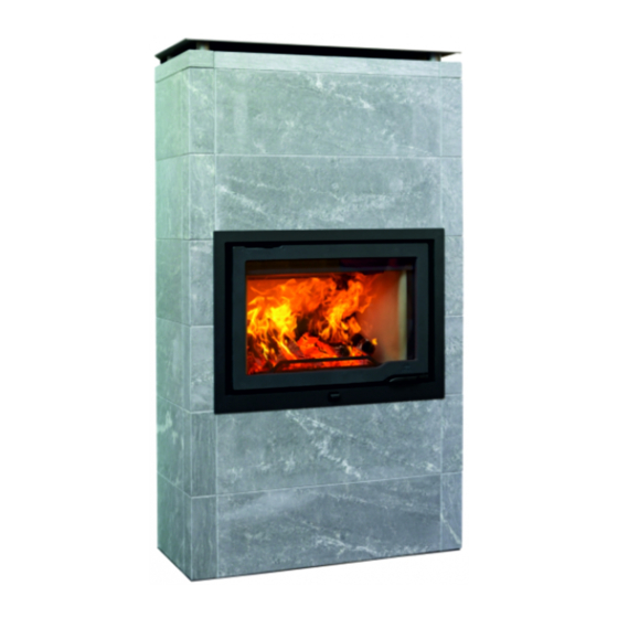
Jotul FS 166 - I 570 Manuel D'installation Et D'utilisation
Masquer les pouces
Voir aussi pour FS 166 - I 570:
- Manuel d'installation et d'utilisation (84 pages)
Publicité
Les langues disponibles
Les langues disponibles
Liens rapides
NO
- Monterings- og bruksanvisning
UK
- Installation and Operating Instructions
FR
- Manuel d'installation et d'utilisation
ES
- Manual de instrucciones
IT
- Installazione e Istruzioni per l'uso
PL
- Instrukcja Montażu i Obsługi
Jøtul FS 166 - I 570
Monterings- og bruksanvisningen må oppbevares under hele produktets levetid. These instructions
must be kept for future references. Ce manuel doit être conservé pour de futures interventions. Wir
empfehlen Ihnen, die Montage- und Bedienungsanleitung für spätere Zwecke sorgfältig aufzubewahren.
Jøtul FS 166 - I 570
2
11
20
29
38
47
Publicité
Chapitres

Manuels Connexes pour Jotul FS 166 - I 570


Sommaire des Matières pour Jotul FS 166 - I 570
- Page 1 Jøtul FS 166 - I 570 - Monterings- og bruksanvisning - Installation and Operating Instructions - Manuel d’installation et d’utilisation - Manual de instrucciones - Installazione e Istruzioni per l’uso - Instrukcja Montażu i Obsługi Jøtul FS 166 - I 570 Monterings- og bruksanvisningen må...
-
Page 2: Table Des Matières
Forhold til myndighetene ......2 Tekniske data ..........2 Jøtul FS 166 - I 570 er et frittstående produkt av kleber der innsatsen, Jøtul I 570, brukes som brennkammer. Produktet kan plasseres mot brennbar vegg med de avstander som er Omrammingens deler ......4 beskrevet i fi... - Page 3 NORSK...
-
Page 4: Omrammingens Deler
NORSK 3.0 Omrammingens deler Fig. 2... -
Page 5: Før Montering
4.2 Tildekking av gulv Det følger 2 manualer med produktet: 1. Jøtul FS 166 - I 570 (omrammingen) Jøtul FS 166 - I 570 har tett bunnplate og trenger ingen ekstra 2. Jøtul I 570 (brennkammeret) tildekking mot gulv under produktet. -
Page 6: Montering
NORSK 4.9 Klargjøring av innsats (fi g. 3B-E). Se avsnitt ”4.1 Utskifting av brennplater/ hvelv/ledeplate.” NB! Kontroller at ildstedet er fritt for skader før installasjonen begynner. Produktet er tungt! Sørg for hjelp når det skal settes opp og monteres. 5.0 Montering Etter at innsatsen er pakket ut, ta ut esken med innhold. - Page 7 NORSK Fig. 6 Fig. 8 A Fest de 4 kassettbeina (fi g. 6 A) til innsatsen med skruene. Skru i fotskruene (fi g. 6 B) på kassettbeina. Juster til riktig NB! Hull i gulv til uteluft. lengde (se fi g. 1 og fi g. 13). Reis produktet forsiktig opp.
- Page 8 NORSK Fig. 9 Fig. 11 brakett 1 brakett 2 brakett 4 brakett 3 brakett 5 brakett 6 Fig. 10 Løft innsatsen opp på stativet. Vær forsiktig da innsatsen er fortung. Sett på plass igjen alle delene som ble fjernet for å lette håndteringen av innsatsen.
- Page 9 NORSK Fig. 12-2 Fig. 14 Bruk brakett 5 (fi g. 14 A) på lag nr. 3 og 4. Juster om nødvendig brakettene for hånd slik at de klemmer steinene best mulig sammen. NB! Før bruk - åpne dæren og fjern skruen (fi g 12-2 A) Fig.
-
Page 10: Ferdig Montert
NORSK 6.0 Ferdig montert Fig. 16 Se den generelle bruks- og vedlikeholdsmanual for Jøtul I 570 vedr. bruk og vedlikehold av produktet! 7.0 Vedlikehold Skulle man være uheldig å få riper i overfl aten, kan det pusses med et fi nt sandpapir. Ved dypere sår kan det lages en pasta av klebersteinpulver og vannglass, og sparkle steinen med dette. -
Page 11: Optional Equipment
ENGLISH 1.0 Relationship with the Table of contents authorities Relationship with the authorities ..11 Technical data........11 Jøtul FS 166 – I 570 is a freestanding product with Jøtul I 570 as the burn chamber, which can be positioned against infl ammable walls at the distances described in Fig. - Page 12 ENGLISH...
-
Page 13: Parts Of The Surround
ENGLISH 3.0 Parts of the surround Fig. 2... -
Page 14: Prior To Installation
Heat shield, top 1 pcs Adjustable leg 4 pcs Make sure the room where the Jøtul FS 166 - I 570 is to be Heat shield for fl ue pipe 1 pcs placed has a ceiling height of at least 2300 mm. -
Page 15: Mounting
ENGLISH 4.9 Preparation/installation Fig. 3 C NB: Check that the fireplace is undamaged before installation begins. The product is heavy! Ensure you have help when positioning and installing it. After unpacking the insert take out the box with contents. To make the product lighter, remove the door. - Page 16 ENGLISH Fig. 5 Fig. 7 Dismount the insert’s heat shield by unscrewing the upper screw on both sides of the insert (fi g. 5 A). Loosen the lower screws (fi g. 5 E) somewhat and pull the heat shield upwards and then remove it. Lay the insert carefully down on its back (you can protect the fl...
- Page 17 ENGLISH Fig. 8 B Fig. 10 50 mm NB!: Do not use corner stones marked «223628» before Assemble the stand. The stand consist of bottom plate the fourth layer. (Fig. 8 B-A), 4 legs (Fig. 8 B-B) and top plate (Fig. 8 B-C). Fit the fi...
- Page 18 ENGLISH Fig. 12 Fig. 13 4 psc. M10x35 Centre the insert laterally. Position the insert and the frame against the front of the surround. Remove the lower cover (Fig.12 A). Make sure that there is clearance between the lower edge Fit the decorative frame over the door and hook it over the of the frame and the stone below (Fig.
-
Page 19: Installation Completed
ENGLISH Fig. 15 Fig. 17 223628 Place the attachment bracket on the special corner stone 223628 (Fig. 15 A). The front stone (Fig. 15 B) of layer 5 shall rest on the attachment bracket. If top smoke outlet: Fig. 16 Place the last layer (Fig. -
Page 20: Équipements En Option
FRANCAIS 1.0 Rapports avec les Sommaire autorités Rapports avec les autorités ....20 Données techniques ......20 Le Jøtul FS 166 – I 570 est un appareil indépendant dont le foyer Jøtul I 570 peut se placer contre des murs infl ammables conformément aux distances décrites en fi... - Page 21 FRANCAIS...
-
Page 22: Vue Éclatée De L'habillage
FRANCAIS 3.0 Vue éclatée de l’habillage Fig. 2... -
Page 23: Avant L'installation
4 pces Veillez à ce que la pièce dans laquelle sera intallé le poêle Jøtul Bride 5 4 pces FS 166 - I 570 ait une hauteur de plafond d’au moins 2 300 mm. Bride 2 6 pces Bride 4 4 pces 4.7 Cheminée et conduits... -
Page 24: Installation
FRANCAIS Avant l’installation, déterminez les points suivants: Fig. 3 C 1. L’emplacement de la sortie d’évacuation des fumées. 2. LLe système de collecte des cendres, si utilisé. Reportez-vous aux manuels correspondants pour les instructions d’installation des pièces. 4.9 Préparation/installation Remarque : assurez-vous que l’insert est en bon état avant de procéder à... - Page 25 FRANCAIS Fig. 5 Fig. 7 Démontez le bouclier thermique de l’insert en dévissant Dévissez le bouclier thermique supérieur à l’arrière (fi g. les vis supérieures de chaque côté de l’insert (fi g. 5 A). 7 A). Retournez-le et fi xez-le fermement en utilisant les Desserrez légèrement les vis inférieures (fi...
- Page 26 FRANCAIS Fig. 8 B Fig. 10 50 mm Assemblez le socle. Celui-ci se compose de la plaque de Remarque : La pierre d’angle 223628 se place au troisième fond (fi g. 8 B-A), de 4 pieds (fi g. 8 B-B) et de la plaque rang.
- Page 27 FRANCAIS Fig. 12 Fig. 13 4 psc. M10x35 Centrez l’insert latéralement. Positionnez-le ainsi que le cadre contre la façade de l’habillage. Enlevez le demi cadre inférieur (fi g.12 A). Veillez à ménager un dégagement entre le bord inférieur Ajustez le cadre décoratif au-dessus de la porte et du cadre et la pierre du dessous (fi...
-
Page 28: Après L'installation
FRANCAIS 6.0 Après l’installation Fig. 16 Pour l’utilisation au quotidien et l’entretien, voir le manuel d’utilisation générale et de maintenance du poêle. 7.0 Maintenance Si les surfaces présentent des rayures, celles-ci peuvent être polies au moyen de papier abrasif à grain fi n. Si les rayures sont semi-profondes, utilisez une poudre à... -
Page 29: Accesorios Opcionales
ESPAÑOL 1.0 Relación con las Indice autoridades Relación con las autoridades .....29 Jøtul FS 166 – I 570 es un producto separado que utiliza Jøtul Datos técnicos ........29 I 570 como cámara de combustión y puede colocarse junto a paredes infl amables a las distancias indicadas en la Fig. 1. Partes del revestimiento ......31 La instalación de la estufa debe hacerse con arreglo a la Antes de la instalación ......32... - Page 30 ESPAÑOL...
-
Page 31: Partes Del Revestimiento
ESPAÑOL 3.0 Partes del revestimiento Fig. 2... -
Page 32: Antes De La Instalación
Compruebe que la altura del techo en la habitación donde se Soporte 1 6 uds. va a instalar la Jøtul FS 166 - I 570 es de al menos 2.300 mm. Soporte 3 uds. 4.7 Chimenea y tubo de tiro Soporte 6 4 uds. - Page 33 ESPAÑOL Tornillo avellanado, M6x16 8 uds. Fig. 3 B Escudo térmico superior 1 uds. Pata ajustable 4 uds. Escudo térmico para tubería de humos 1 uds. Tornillo de cabeza hexagonal, M10x35 4 uds. Tornillo de cabeza hexagonal con brida, M6x10 2 uds.
-
Page 34: Instalación
ESPAÑOL 5.0 Instalación Fig. 6 Nota: La base tiene que estar nivelada con una tolerancia máxima de 1 mm/m. Esto es muy importante para que el resto de la instalación sea correcta. Todas las piedras deben estar niveladas. Compruebe la nivelación de cada nueva capa de piedras. Si fuese necesario, utilice pequeñas piezas de acero o silicona para ajustar la altura de las piedras. - Page 35 ESPAÑOL Fig. 8 A Fig. 9 soporte 1 soporte 2 soporte 2 soporte 4 soporte 3 soporte 5 soporte 6 Nota: Orifi cios en el piso para aire externo. Fig. 10: Fig. 8 B 50 mm Nota: No se deben utilizar las piedras de esquina marcadas 223628 hasta la capa cuarta.
- Page 36 ESPAÑOL Fig. 11 Fig. 12.2 Nota: Antes de usar, abra la puerta, Coloque la cámara de combustión sobre la base. y retire el tornillo (fi g. 12.2 - A). Asegúrese de que la cámara de combustión está en una posición estable. Vuelva a montar todas las piezas que quitó...
-
Page 37: Fin De La Instalación
ESPAÑOL Fig. 17 Fig. 14 Use el soporte 5 (Fig. 14 A) en las capas 3 y 4. Si es necesario, ajuste los soportes con las manos de modo que sujeten las piedras. En caso de salida de humo superior: Fig. -
Page 38: Apparecchiature Opzionali
ITALIANO 1.0 Conformità alle leggi Indice generale Jøtul FS 166 – I 570 è un prodotto mobile che utilizza come Conformità alle leggi ......38 camera di combustione il modello Jøtul I 570 ed è posizionabile contro pareti infi ammabili alle distanze indicate in Fig. 1. Dati tecnici ..........38 L’installazione del caminetto deve avvenire in base ai codici Componenti per il rivestimento ..40... - Page 39 ITALIANO...
-
Page 40: Componenti Per Il Rivestimento
ITALIANO 3.0 Componenti per il rivestimento Fig. 2... -
Page 41: Prima Dell'installazione
1 qtà Assicurarsi che il locale in cui verrà posizionato il prodotto Staff a 1 6 qtà Jøtul FS 166 - I 570 presenti un’altezza dal soffi tto di almeno Staff a 3 10 qtà 2300 mm. Staff a 6 4 qtà... -
Page 42: Installazione
ITALIANO Staff a 2 6 qtà Fig. 3 C Staff a 4 4 qtà Vite a testa svasata, M6x16 8 qtà Scudo termico superiore 1 qtà Gamba regolabile 4 qtà Scudo termico per la canna fumaria 1 qtà Vite a testa esagonale, M10x35 4 qtà... - Page 43 ITALIANO Fig. 5 Fig. 7 Svitare lo scudo termico superiore sul retro (fi g. 7 A). Capovolgerlo e avvitarlo saldamente usando le stesse viti a cui era fi ssato in precedenza. 4. Smontare lo scudo termico dell’inserto svitando la vite In presenza di uno scarico fumi superiore: Montare lo superiore posta su entrambi i lati dell’inserto (fi...
- Page 44 ITALIANO Fig. 8 B Fig. 10 50 mm NB non usare Le pietre ad angolo, marcate 223628, sino al Montare il supporto, composto dalla piastra inferiore (fi g. 8 4 livello come in fi g 15 B- A), dai 4 montanti (fi g. 8 B-B) e dalla piastra superiore Disporre il primo strato di lastre in pietra ollare sulla piastra (fi...
- Page 45 ITALIANO Fig. 12 Fig. 13 4 psc. M10x35 Centrare lateralmente l’inserto. Posizionare l’inserto e la cornice contro la parte anteriore Rimuovere la copertura inferiore (Fig.12 A). del rivestimento. Inserire la cornice decorativa sulla porta e agganciarla Verifi care che vi sia dello spazio vuoto tra il bordo inferiore sopra alla parte anteriore (Fig.
-
Page 46: Completamento Dell'installazione
ITALIANO Fig. 15 In presenza di uno scarico fumi superiore: Collocare l’ultimo strato (Fig. 17 A) e lo strato superiore (Fig. 17 B). Utilizzare la staff a 2, 4 e 6 tra l’ultimo strato e lo strato superiore (Fig. 17 C). Rimuovere l’estrattore e collocare la griglia superiore (Fig. -
Page 47: Wyposażenie Dodatkowe
POLSKI 1.0 Zgodność z Spis treści przepisami Zgodność z przepisami .......47 Dane techniczne ........47 Jøtul FS 166 – I 570 to produkt w wersji wolno stojącej z Jøtul I 570 jako komora spalania, która może być umieszczona przy ścianach wykonanych z materiałów łatwopalnych w Części obudowy ........49 odległościach określonych na Rys. - Page 48 POLSKI...
-
Page 49: Części Obudowy
POLSKI 3.0 Części obudowy Rys. 2... -
Page 50: Przed Montażem
POLSKI 4.0 Przed instalacją 4.8 Komin i rura dymowa • Wkład kominkowy należy podłączyć jedynie do komina i kanału dymowego przeznaczonych do podłączeń 4.1 Nośność podłoża palenisk na paliwa stałe o temperaturze spalin zgodnej ze specyfi kacją podaną w dziale «2.0 Dane techniczne». Należy sprawdzić, czy podłoże jest dostatecznie wytrzymałe •... - Page 51 POLSKI Wspornik 5 4 szt. Rys. 3 B Wspornik 2 6 szt. Wspornik 4 4 szt. Śruba z łbem wpuszczanym, M6x16 8 szt. Blacha osłonowa górna 1 szt. Noga nastawna 4 szt. Blacha osłonowa rury dymowej 1 szt. Śruba z łbem heksagonalnym, M10x35 4 szt.
-
Page 52: Montaż
POLSKI 5.0 Montaż Rys. 6 Uwaga! Podstawa musi być wypoziomowana. Maks. zakres tolerancji wynosi 1mm/m. By pozostałe e t a p y m o n t a ż u p r z e b i e g ł y p r a w i d ł o w o , n a l e ż y zastosować... - Page 53 POLSKI Fig. 8 A Rys. 9 Wspornik 1 Wspornik 2 Wspornik 4 Wspornik 3 Wspornik 5 Wspornik 6 Uwaga! Otwór w podłodze na ujęcie świeżego powietrza. Rys. 10 Rys. 8 B 50 mm Uwaga! Nie używać narożników kamiennych określonych jako ‘223628’ przed czwartą warstwą. Spasować...
- Page 54 POLSKI Rys. 11 Rys. 13 4 psc. M10x35 Umieścić wkład kominkowy ukośnie. Ustawić wkład i ramę na przodzie obudowy. Upewnić się, czy luka pomiędzy dolną krawędzią ramy i Umieścić komorę spalania na podstawie. Upewnić się czy kamieniem znajdującym się poniżej (Rys. 13A) występuje komora spalania jest stabilna.
- Page 55 POLSKI Rys. 15 Rys. 17 223628 Umieścić wspornik mocujący na specjalnym narożniku kamiennym 223628 (Rys. 15A). Kamień przedni (Rys. 15B) warstwy 5 ma spoczywać na tym wsporniku mocującym. Rys. 16 W przypadku górnego przejścia kominowego: Umieścić ostatnią warstwę (Rys. 17A) i warstwę zewnętrzną...
-
Page 56: Montaż Zakończony
POLSKI 6.0 Po zakończeniu montażu By uzyskać informacje na temat eksploatacji i konserwacji urządzenia, należy zapoznać się z ogólną instrukcją eksploatacji i konserwacji dla kominka Jøtul I 570. 7.0 Konserwacja Jeśli po przeprowadzonym montażu znajdziemy rysy na powierzchni, możemy je wypolerować za pomocą drobnego papieru ściernego. - Page 57 SPRÅK...
- Page 58 SPRÅK...
- Page 59 SPRÅK...
- Page 60 fi rst started in 1853. Qualité Notre démarche assure à nos clients une tranquillité d’esprit sur la qualité et la sécurité, due à une expérience remontant à la création de la société en 1853. Jøtul AS, P.o. box 1411 N-1602 Fredrikstad, Norway www.jotul.com...