Publicité
Les langues disponibles
Les langues disponibles
Liens rapides
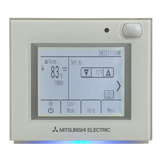
CITY MULTI Control System
Smart ME Controller
Installation Manual
Chapter 1. Installation
This installation manual describes how to install the Smart ME Controller for use with Mitsubishi
Building Air Conditioning System, direct expansion type CITY MULTI air conditioner indoor units.
Please be sure to read this installation manual and Instruction Book that are supplied with the Remote
Controller before proceeding with the installation. Failure to follow the instructions may result in
equipment damage.
For information on how to wire and install the air conditioning units, refer to the Air Conditioner
Installation Manual.
After the installation, hand over this manual to users.
Smart ME Controller is a type of ME Remote Controllers, sometimes simply referred to as ME Remote
Controller.
1
Safety Precautions
• Read the following safety precautions prior to installation.
• Observe these precautions carefully to ensure safety.
WARNING
Indicates a risk of death or serious injury.
CAUTION
Indicates a risk of serious injury or structural damage.
• After reading this manual, pass it on to the end user to retain for future reference.
• Keep this manual for future reference and refer to it as necessary. This manual should be made
available to those who repair or relocate the controller. Make sure that the manual is passed on to
any future users.
All electric work must be performed by qualified personnel.
General precautions
WARNING
Do not install the unit in a place where large amounts of
oil, steam, organic solvents, or corrosive gases, such
as sulfuric gas, are present or where acidic/alkaline
solutions or sprays are used frequently. These
substances can compromise the performance of the
unit or cause certain components of the unit to corrode,
which can result in electric shock, malfunctions,
smoke, or fire.
To reduce the risk of shorting, current leakage, electric
shock, malfunctions, smoke, or fire, do not wash the
controller with water or any other liquid.
To reduce the risk of electric shock, malfunctions,
smoke or fire, do not operate the switches or touch
other electrical parts with wet hands.
PAR-U01MEDU
For distribution to dealers and contractors
To reduce the risk of injury or electric shock, before
spraying a chemical around the controller, stop the
operation and cover the controller.
To reduce the risk of injury or electric shock, stop the
operation and switch off the power supply before
cleaning, maintaining, or inspecting the controller.
Properly install all required covers to keep moisture
and dust out of the controller. Dust accumulation and
water can cause electric shock, smoke, or fire.
To reduce the risk of injury, keep children away while
installing, inspecting, or repairing the controller.
– 1 –
GB
WT06684X03
Publicité

Manuels Connexes pour Mitsubishi Electric CITY MULTI Smart ME Controller


Sommaire des Matières pour Mitsubishi Electric CITY MULTI Smart ME Controller
- Page 1 WT06684X03 CITY MULTI Control System Smart ME Controller PAR-U01MEDU Installation Manual For distribution to dealers and contractors Chapter 1. Installation This installation manual describes how to install the Smart ME Controller for use with Mitsubishi Building Air Conditioning System, direct expansion type CITY MULTI air conditioner indoor units. Please be sure to read this installation manual and Instruction Book that are supplied with the Remote Controller before proceeding with the installation.
- Page 2 CAUTION To reduce the risk of fire or explosion, do not place To avoid injury from broken glass, do not apply flammable materials or use flammable sprays around excessive force on the glass parts. the controller. To reduce the risk of injury, wear protective gear when To reduce the risk of damage to the controller, do not working on the controller.
- Page 3 This controller is designed for exclusive use with the mild detergent, wipe off the detergent with a wet cloth, Building Management System by Mitsubishi Electric. and wipe off water with a dry cloth. The use of this controller for with other systems or for other purposes may cause malfunctions.
- Page 4 Component names and supplied parts The following parts are included in the box. Parts name Qty. Remote controller (front cover) *1 Remote controller (top case) *1 Remote controller (bottom case) Front cover Top case Bottom case Roundhead cross slot screws M4×30 *2 Wood screw 4.1×16 *2 (for direct wall installation) Installation Manual (this manual)
- Page 5 System diagram Group 01 Group 02 Group 03 Outdoor unit Indoor unit Indoor unit Indoor unit Indoor unit LOSSNAY unit Smart ME Smart ME Smart ME Controller Controller *1 Controller Group 04 Outdoor unit Advanced HVAC CONTROLLER (AHC) Indoor unit Indoor unit Indoor unit Indoor unit...
- Page 6 How To Install This remote controller is for the wall installation. It can be installed either in the switch box or directly on the wall. When performing direct wall installation, cables can be thread through either back or top of the remote controller. (1) Selecting an installation site Install the remote controller (switch box) on the site where the following conditions are met.
- Page 7 Occupancy sensor detects occupancy based on the temperature difference between the occupant and its surroundings. To be precise, to enhance the sensitivity of the sensor to occupant movements, the occupancy sensor is designed to detect the changes in the amount of infrared light emitted from an object in the detection zone, including human bodies.
- Page 8 (2) Installation space Leave a space around the remote controller as shown in the figure below, regardless of whether the controller is installed in the switch box or directly on the wall. Removing the remote controller will not be easy with insufficient space. Also, leave an operating space in front of the remote controller.
- Page 9 • Cut out the thin-wall part on the cover (indicated with the shaded area in the right figure) with a knife or a nipper. Note: Make sure that the hole edges are smooth and will not damage the wires. 4 Install the bottom case. •...
- Page 10 6 Connect the remote controller cable to the terminal block on the top case. Connect the remote controller cable to the terminal block. Connect the cable to the terminal block, and insert the cable into the groove. To reduce the risk of electric shock, shorting, or malfunctions, keep wire pieces and sheath shavings out of the terminal block.
- Page 11 7 Set the M-NET addresses. Rotary switches 10's digit (Above) 1's digit (Below) (Ex: Address 108) Address range Address setting method Address that equals the lowest address of the Main remote controller 101 to 150 group plus 100 Address that equals the lowest address of the Sub remote controller 151 to 200 group plus 150...
- Page 12 ■ Direct wall installation (when running the cable along the wall) Putty • Thread the cable through the access hole at the top of the remote controller. • Seal the cut-out part of the cover with putty. • Use a cable cover. Installation is complete.
- Page 13 Important ■ Discrepancy between the room temperature measured at the wall and the actual room temperature may occur. If the following conditions are met, the use of the temperature sensor on the indoor unit is recommended. • Air distribution in the space is poor. •...
- Page 14 Chapter 2. Initial Setting This chapter contains information about the settings to be made at the time of installation. Please read the instructions carefully and make the settings accordingly. Refer to Chapter 1 “Installation” for how to install the Remote Controller, and refer to the air conditioning unit installation manuals for how to connect the controller cable to the air conditioning units, or how to install the air conditioning units.
- Page 15 (2) Setup screen (a) Group setting Use this screen to register the indoor units and the AHC to be controlled from the controller. 1 Select an indoor unit or an AHC address in the [Address] field. The number of units that can be registered. Indoor unit: 16 units maximum AHC: 1 unit maximum * AHC cannot be controlled from the controller unless indoor...
- Page 16 Service Menu [HOME screen] [MENU(User) screen] [MENU(Service) screen] A password is required to access the Menu Service screen or some settings under the Menu User screen • The initial Service password is “9999.” The initial User password is “0000.” Change the password as necessary to prevent unauthorized access.
- Page 17 Item Detail Description Setting Default (1) Setup (i) Room name Use to enter room names (max. Use a combination of Blank 16 characters). The names capital letters, small- entered here will appear on the case letters, numerical HOME screen. characters and symbols. Telephone Use to enter the telephone Use numerical...
- Page 18 (1) Setup menu (a) Group setting Refer to section 1 "Initial Settings" (2) "Setup screen". (b) Interlocked LOSSNAY Refer to section 1 "Initial Settings" (2) "Setup screen". (c) Search connection information Refer to section 1 "Initial Settings" (2) "Setup screen". (d) Cool/Heat display (e) Override control (f) Temperature sensor offset...
- Page 19 (j) Telephone number (k) IC function settings (max. 13 numbers) 1Select the indoor unit address in the [M-NET address] field. (When [Grp] has been selected, all the indoor units that are controlled from the controller will be selected.) 2Select the desired function number in the [Function number] field.
- Page 20 (m) Reset RC (n) AHC port name (max. 20 characters) (2) Error Menu (a) Error history (b) Self check (max. 16) – 20 –...
- Page 21 (3) Test Run [Indoor unit setting screen] [Test run screen] (a) Read the section about Test run in the indoor unit Installation Manual before performing a test run. (b) During the test run, indoor units will be forced to operate in the Thermo-ON status. Except the set temperature, normal operation functions are accessible during test run.
- Page 22 Specifications Receives power from outdoor units via the M-NET 17-32 VDC *1 Power Source transmission cable. The power consumption (for connection to M-NET only) coefficient* of the Smart ME Controller is “0.5”. Operating temperature range 0ºC – +40ºC (+32ºF – +104ºF) Temperature Operating conditions Storage temperature range...
- Page 23 – 23 –...
- Page 24 This product is designed and intended for use in the residential, commercial and light-industrial environment. The product at hand is based on the following EU regulations: • Electromagnetic Compatibility Directive 2004/108/EC • Restriction of Hazardous Substances 2011/65/EU Please be sure to put the contact address/telephone number on this manual before handing it to the customer.
- Page 25 WT06921X03 Système de contrôle CITY MULTI Smart ME Controller PAR-U01MEDU Manuel d'installation Destiné aux revendeurs et aux sous-traitants Chapitre 1. Installation Ce manuel d'installation décrit comment installer le Smart ME Controller en vue de son utilisation avec le système de climatisation de bâtiment Mitsubishi, les unités intérieures de climatiseurs CITY MULTI de type extension directe.
- Page 26 Précautions générales AVERTISSEMENT N'installez pas l'unité en un endroit où se trouvent de Pour éviter tout risque de blessure ou d'électrocution, grandes quantités d'huile, de vapeur, de solvants éteignez le contrôleur et couvrez-le avant de pulvériser organiques ou de gaz corrosifs tels du gaz sulfurique un quelconque produit chimique dans l'environnement ou encore là...
- Page 27 ATTENTION N'installez pas le contrôleur dans un endroit exposé à Lors de l'installation du couvercle et du boîtier l'eau ou dans un environnement soumis à la supérieur sur le boîtier inférieur, appuyez dessus condensation afin de prévenir tout risque de court- jusqu'à...
- Page 28 Précautions supplémentaires Pour prévenir tout dommage au contrôleur, utilisez des N'utilisez pas de benzène, de diluant ou d'abrasif outils appropriés pour son installation, son inspection chimique pour nettoyer le contrôleur, afin d'éviter de le ou sa réparation. décolorer. Pour nettoyer le contrôleur, essuyez-le avec un chiffon doux imbibé...
- Page 29 Noms des composants et pièces fournies Les pièces suivantes sont incluses dans l'emballage. Nom des pièces Qté Contrôleur à distance (couvercle avant) *1 Contrôleur à distance (boîtier supérieur) *1 Contrôleur à distance (boîtier inférieur) Couvercle Boîtier Boîtier avant supérieur inférieur Vis cruciformes à...
- Page 30 Schéma du système Groupe 01 Groupe 02 Groupe 03 Unité extérieure Unité intérieure Unité intérieure Unité intérieure Unité intérieure Unité LOSSNAY Smart ME Smart ME Smart ME Controller Controller *1 Controller Groupe 04 Unité extérieure Advanced HVAC CONTROLLER (AHC) Unité intérieure Unité...
- Page 31 Procédure d'installation Ce contrôleur à distance est destiné à une installation murale. Il est possible de l'installer dans le boîtier de connexion ou directement au mur. Lors d'une installation murale directe, les câbles peuvent être acheminés par l'avant ou l'arrière du contrôleur à distance. (1) Sélection d'un site d'installation Installez le contrôleur à...
- Page 32 Capteur d'occupation Sens horizontal Sens vertical Contrôleur à distance 110° 11° Contrôleur à distance 31° 20° Figure1 Figure2 : Zone de détection * Le capteur d'occupation se caractérise par le fait qu'il est plus sensible aux mouvements à travers la zone indiqués par qu'aux mouvements en direction du capteur.
- Page 33 Capteur de luminosité Sens horizontal Sens vertical Contrôleur à distance 22° Contrôleur à distance 44° 44° 22° Figure3 Figure4 Consignes de manipulation • Veillez à ne pas rayer la lentille. • Ne collez pas de ruban adhésif ou d'étiquettes sur la lentille. •...
- Page 34 (2) Espace d'installation Que le contrôleur à distance soit installé dans le boîtier de connexion ou directement sur le mur, laissez un espace autour du contrôleur comme indiqué sur la figure ci-dessous. Le retrait du contrôleur à distance ne sera pas facile si l'espace est insuffisant. Laissez également un espace de fonctionnement devant le contrôleur à...
- Page 35 3 Préparez le boîtier inférieur du contrôleur à distance. * Procédez comme suit uniquement lors de l'installation murale directe avec acheminement du câble du contrôleur à distance le long du mur. Boîtier inférieur • Découpez la partie peu épaisse sur le boîtier (indiquée par la zone grisée sur la figure de droite) avec un couteau ou une pince.
- Page 36 5 Installez le boîtier supérieur sur le boîtier inférieur. Deux pattes de montage sont situées en haut du boîtier supérieur. Accrochez ces deux pattes sur le boîtier inférieur et enclenchez le boîtier supérieur. Vérifiez que le boîtier est correctement installé et ne se soulève pas.
- Page 37 7 Configurez les adresses M-NET. Interrupteurs rotatifs Dizaines (en haut) Unités (en bas) (Ex : adresse 108) Plage d'adresses Méthode de réglage des adresses Contrôleur à distance Adresse correspondant à la plus petite adresse 101 à 150 principal du groupe plus 100 Contrôleur à...
- Page 38 ■ Installation au mur directe (en acheminant le câble le long du mur) Mastic • Acheminez le câble par le trou d'accès en haut du contrôleur à distance. • Bouchez la partie découpée du couvercle avec du mastic. • Utilisez un cache de câble. L'installation est terminée.
- Page 39 Important ■ Un écart entre la température de la pièce mesurée au niveau du mur et la température réelle de la pièce peut survenir. Si les conditions suivantes sont remplies, l'utilisation du capteur de température sur l'unité intérieure est recommandée. •...
- Page 40 Chapitre 2. Paramétrage initial Ce chapitre contient des informations sur les réglages à effectuer au moment de l'installation. Veuillez lire attentivement les instructions et configurer les paramètres en conséquence. Reportez-vous au Chapitre 1 « Installation » pour en savoir plus sur l'installation du contrôleur à distance, aux manuels d'installation des unités de climatisation pour en savoir plus sur la connexion du câble du contrôleur aux climatiseurs ou l'installation des climatiseurs.
- Page 41 (2) Écran de configuration (a) Réglage de groupe Utilisez cet écran pour enregistrer les unités intérieures et l'AHC à contrôler à partir du contrôleur. 1 Sélectionnez une unité intérieure ou une adresse AHC dans le champ [Adresse]. Nombre d'unités pouvant être enregistrées. Unité...
- Page 42 (c) Recherche info connexion Utilisez cet écran pour spécifier une unité et rechercher des contrôleurs qui y sont connectés. 1 Sélectionnez une adresse dans le champ [Adresse]. 2 Appuyez sur la touche [Conf] pour rechercher des unités interconnectées. Les résultats apparaissent dans la colonne de gauche. (Lorsque plusieurs unités sont détectées, les adresses qui ne contiennent pas sur la première page apparaissent sur les pages suivantes.)
- Page 43 Paramètres du menu Service Paramètre Détail Description Réglage Par défaut (1) Confi- (a) Réglage de Permet de définir le réglage de Veuillez vous référer à – groupe gura- groupe des unités intérieures la section 1 tion et d'un AHC « Paramètres initiaux » (2) «...
- Page 44 Paramètre Détail Description Réglage Par défaut (1) Confi- Réglage des Permet de régler la couleur Permet de définir les Bleu : R, G, B = 0, 0, 100 gura- couleurs des voyants LED. *3 ratios de couleur R Bleu clair : R, G, B = 0, 40, 60 tion (Rouge), G (Vert), B Violet : R, G, B = 40, 0, 100...
- Page 45 (1) Menu Configuration (a) Réglage de groupe Veuillez vous référer à la section 1 « Paramètres initiaux » (2) « Écran de configuration ». (b) Interconnexions LOSSNAY Veuillez vous référer à la section 1 « Paramètres initiaux » (2) « Écran de configuration ». (c) Recherche info connexion Veuillez vous référer à...
- Page 46 (h) Mode auto unique/double (i) Nom de la salle (max. 16 caractères) (j) Numéro de téléphone (k) Réglages fonction unité int. (max. 13 chiffres) 1Sélectionnez l'adresse de l'unité intérieure dans le champ [Adresse M-NET]. (Si [Grp] a été sélectionné, toutes les unités intérieures contrôlées à partir du contrôleur seront sélectionnées.) 2Sélectionnez le numéro de fonction souhaité...
- Page 47 (l) Réglage des couleurs LED R (Rouge), G (Vert), B (Bleu) : « + »···plus clair, « – »···plus sombre Reset : Restaure les paramètres par défaut de la couleur d'affichage. (m) Réinitialiser la télécommande (n) Nom du port AHC (max.
- Page 48 (2) Menu d'erreurs (a) Historique des erreurs (b) Auto contrôle (max. 16) – 24 –...
- Page 49 (3) Test fonct. [Écran Réglage unité intérieure] [Écran Test fonct.] (a) Lisez la section sur le test de fonctionnement du manuel d'installation de l'unité intérieure avant d'exécuter un test de fonctionnement. (b) Pendant le test de fonctionnement, les unités intérieures devront fonctionner en mode Thermo actif.
- Page 50 Caractéristiques Reçoit l'alimentation des unités extérieures via le 17-32 V CC *1 câble de transmission M-NET. Le coefficient de Source d'alimentation (connexion à M-NET consommation électrique* du Smart ME uniquement) Controller est de 0,5. Plage de températures en 0 ºC à +40 ºC (+32 ºF à +104 ºF) fonctionnement Température Conditions...
- Page 51 – 27 –...
- Page 52 Ce produit est conçu et prévu pour un usage résidentiel, commercial et dans un environnement industriel léger. Ce produit est conforme aux réglementations de l'Union européenne suivantes : • Directive 2004/108/CE sur la compatibilité électromagnétique • Directive 2011/65/UE relative à la limitation des substances dangereuses Veillez à...