Intermatic ST01K Serie Instructions D'installation Et Mode D'emploi
Les langues disponibles
Les langues disponibles
Liens rapides
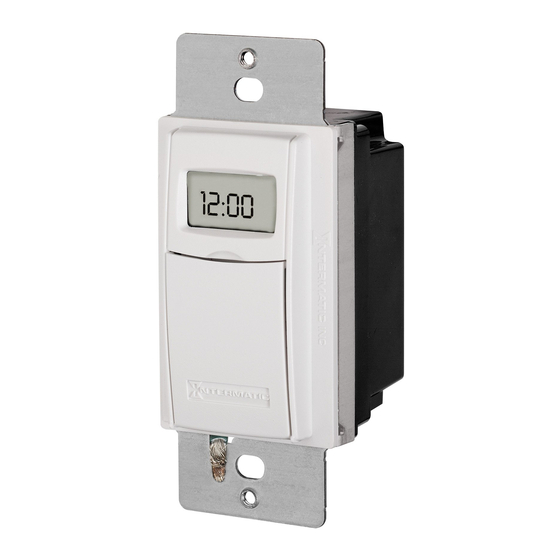
IN-Wall Timer with Astro Feature
MODEL ST01K SERIES
Installation and User Instructions
Risk of Fire or Electric Shock
WARNING
•
Disconnect power at the circuit breaker(s) or disconnect switch(es) before
installing or servicing.
•
Installation and/or wiring must be in accordance with national and local
electrical code requirements.
•
Use COPPER conductors ONLY.
•
Do Not recharge, disassemble, heat above 212° F (100° C), crush, or incinerate
the non-replaceable Lithium battery. Keep Out of Reach of Children. Replace
only with Panasonic type CR2 or equivalent CR2 battery approved by
Underwriter's Laboratories (UL). Use of a different battery may present a risk of
fi re or explosion upon disposal of battery.
•
Do NOT use timer to control devices that could have dangerous consequences
due to inaccurate timing, such as: sun lamps, saunas, heaters, crock pots, etc.
NOTICE
•
Risk of timer damage due to leakage if weak battery is not replaced promptly.
•
Dispose of product per local regulations for disposal of Lithium batteries.
Ratings
• Resistive (heater) 15 A, 120-277 VAC
• Tungsten (incandescent) 15 A, 120 VAC, 6 A, 208-277 VAC
• Ballast (fl uorescent) 8 A, 120 VAC, 4 A, 208-277 VAC
• Motors 1 H.P. @ 120 VAC, 2 H.P. @ 240 VAC
• DC Loads 4 A, 12 VDC, 2 A, 28 VDC
Installing the Battery
1.
Open the access door to locate the battery tray, located below the ON/OFF keypad.
2.
If there is a pull tab at the battery tray, remove the tab to connect the installed
battery.
3.
Make sure battery tray is pushed fully into place.
4.
Place the supplied "CR2" battery into the tray, observing + and - markings on tray.
5.
Replace the battery tray into the switch timer.
6.
The display will initialize itself then fl ash "12:00AM" in MANual mode.
Press the ON/OFF button. The switch timer should "click"
7.
Clearing the Timer
1.
Press and hold down the ON/OFF button.
Using a paper clip or pen, press and release the RESET button.
2.
When INIT appears on the screen, release ON/OFF. The screen displays 12:00 am.
3.
Setting the Time and Date
North
1.
Press MODE to display SETUP. and
then press ON/OFF.
Center
Press + or - to set the current hour. and
2.
then press ON/OFF.
South
3.
Press + or - to set the current minute
and then press ON/OFF.
4.
Press + to advance the year if needed.
- Press ON/OFF.
5.
Press + or - to change the month. - Press ON/OFF.
6.
Press + or - to change the date and then press ON/OFF.
7.
Press ON/OFF to choose DST (Daylight Saving Time)
• Press + to select Man if you do not observe DST, or
• Press + again to select Auto to automatically set for DST.
Press ON/OFF to choose zone.
8.
9.
Press + to select your zone. See Fig10.
10. Press ON/OFF to review Dawn Time.
11. Press ON/OFF twice to review Dusk Time.
12. Press ON/OFF twice to save.
Programming Dusk ON/Dawn Off
1.
Press MODE to display PGM.
2.
Press ON/OFF to scroll to DUSK.
3.
Press ON/OFF to choose the days you need, then press + to change days from ALL, M-F,
WeeKenD, or individual day.
Press ON/OFF to SAVE your work. - Press + to go to Program 2.
4.
5.
Press ON/OFF twice to display DAWN.
6.
Press ON/OFF to choose the days you need, then press + to change days from ALL, M-F,
WeeKenD, or individual day.
7.
Press ON/OFF to SAVE your work. - Press MODE to display AUTO.
Programming Dusk ON/Fixed Time OFF
1.
Press MODE to display PGM. - Press ON/OFF three times to choose DUSK.
2.
Press ON/OFF to choose the days you need, then press + to change days from
ALL, M-F, WeeKenD, or individual day.
Press ON/OFF to SAVE your work.
3.
Press + to go to Program 2. - Press ON/OFF twice to display DAWN.
4.
5.
Press + until you get to 12:00 pm. - Press ON/OFF.
6.
Press + or - to set the hour of the OFF time. - Press ON/OFF.
7.
Press + or - to set the minutes of the OFF time.
8.
Press ON/OFF to choose the days you need, then press + to change days from
ALL, M-F, WeeKenD, or individual day.
9.
Press ON/OFF to SAVE your work. - Press MODE to display AUTO.
Programming Fixed Time ON/Fixed Time OFF
1.
Press MODE to display PGM. - Press ON/OFF button three times to choose DUSK.
Press + to change it to 12:00 pm. - Press ON/OFF.
2.
3.
Press + or - to set the hour for the ON time. - Press ON/OFF.
4.
Press + or - to set the minutes.
5.
Press ON/OFF to choose the days you need, then press + to change days from
ALL, M-F, WeeKenD, or individual day.
Press ON/OFF to SAVE and then press + to go to Program 2.
6.
Press ON/OFF twice to display Dawn.
7.
8.
Press + to change it to 12:00 pm. - Press ON/OFF.
9.
Press + or - to set the hour for the OFF time. - Press ON/OFF.
10. Press + or - to set the minutes.
11. Press ON/OFF to choose the days you need, then press + to change days from ALL,
M-F, WeeKenD, or individual day.
12. Press ON/OFF to SAVE your work. - Press MODE button to display AUTO.
Installing the switch timer
1.
Turn off power at the service panel.
2.
Remove the existing wall switch.
3.
Trim building wires to 7/16" as shown.
Single Switch Setup
1.
Connect one of the two wires from the wall to the black wire from the switch timer, using
the twist connectors provided.
2.
Connect the other wire from the wall to the blue wire from the switch timer, using the
twist connectors provided.
NOTE: The RED wire is not used in single-switch installations. Cap with a twist connector.
3.
Connect the GREEN wire to the grounding screw in the box. If a plastic box, connect to
ground as supplied.
4.
Make sure all twist connectors are tight.
All manuals and user guides at all-guides.com
3-Way Switch Setup
NOTE: The distance between switch timer and remote switch must
not exceed 100 feet.
1. Locate the COMMON wire connected to fi rst old switch. It might
2. Connect BLACK wire from switch timer to
3. Connect the other two wires from the old
4. Connect green wire to grounding screw in the box.
5. Remove wire "C" from the "Common" terminal of
6. Reconnect wires "B" and "C" to the common termi-
NOTE: For new construction or replacing a dimmer switch, a lighted switch, or a 3-way
switch without screw terminals, a single-pole switch can be used at the remote location. If
unable to determine the proper wire colors, choose one of the wires and connect as wire B.
After the installation is complete, if the controlled light or device will not turn on properly,
reverse wires "A" and "B". See Steps 11 and 12 for how to check.
7. Tuck wires into the timer wall box leaving room for the timer.
8. Using screws provided, mount the switch timer into the wall box, and install wall plate.
9. Install the remote 3-way switch in its box and install wall plate. Turn power ON.
North
Center
10. Make sure MAN mode appears.
South
11. Press ON/OFF button on the switch timer several times. Each time you push the ON/
Fig. 10
Fig. 8
12. Verify the controlled load turns on or off each time the remote switch is operated.
Multiple Time Switch Setup
• Multiple timers may be mounted in an unlimited number of adjacent junction box slots
• No derating is required for multiple switch timers.
For a 3-Switch Setup follow the diagram below.
Four or more switch setups
Use the preceding 3-switch installation diagram and connect 4-way switch wires between the
two 3-way switches.
NOTE: The remote switch(es) may not function when the accumulated wire length to the
remote switch(es) exceeds 100 feet or the wiring to the remote switch(es) is buried under-
ground. Contact Intermatic customer service for further information.
NOTE: Remote switches from a previous conventional installation may not function reliably
with an electronic timer. Try a new remote switch if function is intermittent.
If within the warranty period specifi ed, this product fails due to a defect in material or workmanship,
Intermatic Incorporated will repair or replace it, at its sole option, free of charge. This warranty is extended
to the original household purchaser only and is not transferable. This warranty does not apply to: (a) damage
to units caused by accident, dropping or abuse in handling, acts of God or any negligent use; (b) units which
have been subject to unauthorized repair, opened, taken apart or otherwise modifi ed; (c) units not used in
accordance with instructions; (d) damages exceeding the cost of the product; (e) sealed lamps and/or lamp
bulbs, LED's and batteries; (f) the fi nish on any portion of the product, such as surface and/or weathering,
as this is considered normal wear and tear; (g) transit damage, initial installation costs, removal costs, or
reinstallation costs.
INTERMATIC INCORPORATED WILL NOT BE LIABLE FOR INCIDENTAL OR CONSEQUENTIAL DAMAGES.
SOME STATES DO NOT ALLOW THE EXCLUSION OR LIMITATION OF INCIDENTAL OR CONSEQUENTIAL
DAMAGES, SO THE ABOVE LIMITATION OR EXCLUSION MAY NOT APPLY TO YOU. THIS WARRANTY IS IN
LIEU OF ALL OTHER EXPRESS OR IMPLIED WARRANTIES. ALL IMPLIED WARRANTIES, INCLUDING THE
WARRANTY OF MERCHANTABILITY AND THE WARRANTY OF FITNESS FOR A PARTICULAR PURPOSE,
ARE HEREBY MODIFIED TO EXIST ONLY AS CONTAINED IN THIS LIMITED WARRANTY, AND SHALL BE
OF THE SAME DURATION AS THE WARRANTY PERIOD STATED ABOVE. SOME STATES DO NOT ALLOW
7/16"
LIMITATIONS ON THE DURATION OF AN IMPLIED WARRANTY, SO THE ABOVE LIMITATION MAY NOT
APPLY TO YOU.
This warranty service is available by either (a) returning the product to the dealer from whom the unit
was purchased or (b) completing a warranty claim online at www.intermatic.com.
This warranty is made by: Intermatic Incorporated, Customer Service 7777 Winn Rd., Spring Grove,
Illinois 60081-9698. For warranty service go to: http://www.Intermatic.com or call 815-675-7000.
be attached to a different colored screw, or fi nd markings on old
switch.
COMMON wire, using a twist connector.
switch to the blue and re wires from the timer.
If plastic box, connect to ground.
the existing remote switch.
nal of your remote switch, using the supplied piece
of jumper wire. If using a new single-pole remote
switch. See diagram 3.
DIAGRAM 1:
"COMMON" TERMINAL
TYPICAL
LINE
WIRE "A"
EXISTING
WIRE "B"
2-SWITCH
3-WAY
SETUP
REMOTE SWITCH
MAIN SWITCH
DIAGRAM 2:
LINE
BLUE
2-SWITCH SETUP,
BLACK
TIMER INSTALL
TIMER
RE-USING EXISTING
RED
WIRE "A"
REMOTE 3-WAY SWITCH
NOT USED
DIAGRAM 3:
LINE
BLUE
2-SWITCH SETUP,
BLACK
TIMER INSTALL USING
TIMER
NEW SINGLE-POLE
RED
REMOTE SWITCH
OFF button, the switch timer should '"click" and the controlled light or device (the "load")
should turn on or off. If so, proceed to Step12.
- If timer clicks but load does activate, check wiring and make sure load is functional.
- If the timer clicks but the load only operates when the remote switch is in one of its
2 positions, you need to turn off the power at the service panel, then reverse wires
"A" and "B". You can reverse wires "A" and "B" at the remote switch wall box, or you
can reverse wires "A" and "B" where they connect to the red and blue wires of the
switch timer. Then turn power back on at the service panel and repeat Step 11.
Multiswitch applications using the ST01 timer are wired differently than conventional
toggle switches. Read the following installatin instructions carefully.
ADDITIONAL WIRE
BLUE
BLACK
TIMER
LINE
RED
TWO 3-WAY SWITCHES
LIMITED ONE-YEAR WARRANTY
BLACK WIRE
BLUE WIRE
RED WIRE
(capped, not connected)
RED WIRE
BLUE WIRE
WIRE FROM
"COMMON" OF
OLD SWITCH
BLACK WIRE
LOAD
WIRE "C"
NEUTRAL
3-WAY
LOAD
NEUTRAL
WIRE "C"
WIRE "B"
JUMPER
"COMMON" TERMINAL
3-WAY
REMOTE SWITCH
LOAD
NEUTRAL
WIRE "C"
WIRE "B"
JUMPER
WIRE "A"
SINGLE-POLE REMOTE SWITCH
LOAD
NEUTRAL

Manuels Connexes pour Intermatic ST01K Serie


Sommaire des Matières pour Intermatic ST01K Serie
- Page 2 2. Appuyer sur + faire avancer l’heure jusqu’à 12:00 PM. Appuyer sur ON/OFF. Si, dans la période de garantie spécifi ée, ce produit tombait en panne dû à un vice de matériau ou de fabrication, Intermatic 3. Appuyer sur + ou - pour régler les heures de l’événement ON (marche). Appuyer sur ON/OFF.