
Manuels Connexes pour Heidolph Hei-FLOW Core

Sommaire des Matières pour Heidolph Hei-FLOW Core
- Page 1 Precise Dosing and Suspending Betriebsanleitung Operating instructions Notice d'instructions Hei-FLOW Core Hei-FLOW Expert Hei-FLOW Ultimate...
- Page 2 Originalbetriebsanleitung Seite 6 – 48 Translation of the original instructions Page Page 54 – 96 Traduction de la notice originale Page 102 – 144 Zertifikate/Certifications Seite/page 145– 149...
- Page 3 Besondere Hygienemaßnahmen für den Einsatz von Laborgeräten in der Nahrungsmittel-, Kosmetik- und Pharmaproduktion ........11 Allgemeine Maßnahmen ..................11 Gerätespezifische Maßnahmen ................11 Sonstige Regularien ................12 Gerätebeschreibung Übersicht Hei-FLOW Core ................ 13 Übersicht Hei-FLOW Expert ..............13 Übersicht Hei-FLOW Ultimate ..............14 Bedienfeld Hei-FLOW Ultimate ..............14...
- Page 4 Inbetriebnahme Gerät aufstellen..................15 Netzspannungsversorgung ..............15 Bedienung Gerät ein-/ausschalten ................16 Pumpbetrieb Hei-FLOW Core ..............16 Pumpbetrieb Hei-FLOW Expert ..............17 Schnelles Befüllen/Entleeren ................17 Pumpbetrieb Hei-FLOW Ultimate .............. 18 Pumpenkopf auswählen ..................18 Betriebsparameter ..................... 19 Pumpe kalibrieren ....................20 Drehrichtung anwählen ..................
- Page 5 Technische Daten .................. 43 Leistungsbereich ................... 44 Lieferumfang ..................45 Servicearbeiten ..................46 Reinigungshinweise .................... 46 Reparaturen ...................... 46 Wartung ......................46 Entsorgung ................... 47 Kontaktdaten Deutschland – Österreich – Schweiz ........47 Garantieerklärung .................. 47 Unbedenklichkeitserklärung ..............48...
-
Page 6: Zu Diesem Dokument
Verwendung durch den Käufer des Produkts bestimmt. Jedwede Überlassung an Dritte, Vervielfältigung in jeglicher Art und Form – auch auszugsweise – sowie die Verwertung und/oder Mitteilung des Inhalts sind ohne schriftliche Genehmigung der Heidolph Instruments GmbH & Co. KG nicht gestattet. Zuwiderhandlungen verpflichten zu Schadenersatz. -
Page 7: Bestimmungsgemäße Verwendung
Diese werden an entsprechender Stelle im vorliegenden Dokument ausgewiesen und beschrieben. Bestimmungsgemäße Verwendung Peristaltikpumpen des Typs Heidolph Hei-FLOW Core und Hei-FLOW Expert wurden speziell für das Fördern von Flüssigkeiten entwickelt. Peristaltikpumpen des Typs Heidolph Hei-FLOW Ultimate wurden speziell für das Fördern und Dosieren von Flüssigkeiten entwickelt. -
Page 8: Transport
Allgemeine Hinweise Transport Vermeiden Sie beim Transport starke Erschütterungen und mechanische Belastungen, die zu Schäden am Gerät führen können. Bewahren Sie die Originalverpackung zur späteren Verwendung an einem trockenen und geschützten Ort auf! Lagerung Lagern Sie das Gerät grundsätzlich in der Originalverpackung. Zum Schutz gegen Schäden und unverhältnismäßige Materialalterung sollte das Gerät in möglichst trockener, temperaturstabiler und staubfreier Umgebung gelagert werden. -
Page 9: Allgemeine Sicherheitshinweise
Stellen Sie vor jeder Inbetriebnahme sicher, dass weder das Gerät noch die Netzanschlussleitung sichtbare Schäden aufweisen. ➜ Lassen Sie Reparaturen und/oder Wartungsarbeiten am Gerät ausschließlich von einer autorisierten Elektrofachkraft oder vom technischen Service der Fa. Heidolph Instruments durchführen. ➜ Schalten Sie das Gerät vor der Durchführung von Wartungs-, Reinigungs- oder Reparaturarbeiten grundsätzlich AUS und trennen Sie das Gerät vom Netz. -
Page 10: Persönliche Schutzausrüstung (Psa)
Sicherheit Arbeitssicherheit ➜ Verwenden Sie stets die vorgeschriebene persönliche Schutzausrüstung (PSA), z.B. Schutzkleidung, Schutzbrille, Schutzhandschuhe, Sicherheitsschuhe usw. ➜ Betreiben Sie in der unmittelbaren Umgebung des Geräts keine anderen Geräte ... – die elektromagnetische Felder im Frequenzbereich 9 × 10 Hz bis 3 × 10 erzeugen können, –... -
Page 11: Allgemeine Maßnahmen
Achten Sie auch bei Produkten, die zur einmaligen Nutzung bestimmt sind, auf ausreichende Reinheit. ➜ Verwenden Sie keine offenen Behälter. ➜ Vermeiden Sie Kontamination durch unbedachten Umgang mit belasteten Gefäßen, Apparaturen oder Hilfsmitteln. Kontakt Für weiterführende Auskünfte steht Ihnen unsere Kundenbetreuung jederzeit gerne zur Verfügung. Tel.: +49-9122-9920-0 Mail: sales@heidolph.de... - Page 12 Im Falle der Nichtbeachtung der vorstehend genannten Sicherheitsmaßnahmen und/oder im Falle der Zuwiderhandlung erlischt jeglicher Garantieanspruch gegenüber Heidolph Instruments. Für sämtliche Schäden, die aus eigenmächtigen Änderungen oder Umbauten am Gerät, aus der Verwendung nicht zuge- lassener oder nicht originaler Ersatz- und Zubehörteile bzw.
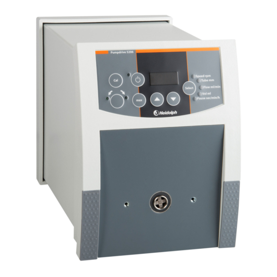
- Page 13 Gerätebeschreibung Gerätebeschreibung Übersicht Hei-FLOW Core Übersicht Hei-FLOW Expert...
- Page 14 Gerätebeschreibung Übersicht Hei-FLOW Ultimate Bedienfeld Hei-FLOW Ultimate...
-
Page 15: Gerät Aufstellen
Die Sicherstellung einer sach- und fachgerechten Aufstellung und Positionierung des Geräts und aller Zubehörteile liegt ausschließlich im Verantwortungsbereich des Betreibers. Heidolph Instruments übernimmt keinerlei Verantwortung für direkte und/oder indirekte Personen- oder Sachschäden, die durch die Nichtbeachtung der Hinweise zur korrekten Aufstellung des Geräts entstehen. -
Page 16: Gerät Ein-/Ausschalten
Schalten Sie das Gerät wie im Abschnitt „Gerät ein-/ausschalten“ auf Seite 16 beschrieben ein. ➜ Stellen Sie mit dem Drehregler [Geschwindigkeit] die gewünschte Pumpgeschwindigkeit ein (siehe auch Abschnitt „Übersicht Hei-FLOW Core“ auf Seite 13). – Die Pumpgeschwindigkeit kann jederzeit im laufenden Betrieb angepasst werden. ➜... - Page 17 Bedienung Pumpbetrieb Hei-FLOW Expert ➜ Schalten Sie das Gerät wie im Abschnitt „Gerät ein-/ausschalten“ auf Seite 16 beschrieben ein. ➜ Stellen Sie mit dem Drehregler [Geschwindigkeit] die gewünschte Pumpgeschwindigkeit ein (siehe auch Abschnitt „Übersicht Hei-FLOW Expert“ auf Seite 13). – Die Pumpgeschwindigkeit kann jederzeit im laufenden Betrieb angepasst werden.
- Page 18 Bedienung Pumpbetrieb Hei-FLOW Ultimate Pumpenkopf auswählen Peristaltikpumpen des Typs Hei-FLOW Ultimate werden standardmäßig mit der Pu 1 Einstellung (Pumpenkopf SP quick) ausgeliefert. Diese Einstellung muss entspre- chend des gewählten Pumpenkopfs angepasst werden: ➜ Schalten Sie das Gerät aus. ➜ Drücken Sie die Taste [Cal]. ➜...
- Page 19 Bedienung Betriebsparameter Die Betriebsparameter der Peristaltikpumpen des Typs Hei-FLOW Ultimate werden über das frontseitige Bedienfeld eingestellt (siehe auch Abschnitt „Bedienfeld Hei-FLOW Ultimate“ auf Seite 14). ➜ Schalten Sie das Gerät wie im Abschnitt „Gerät ein-/ausschalten“ auf Seite 16 beschrieben ein. ➜...
- Page 20 Bedienung Pumpe kalibrieren Zum Ausgleich von Schlauch-Fertigungstoleranzen und zur Gewährleistung bester Dosierergebnisse empfiehlt es sich, die Pumpe in regelmäßigen zeitlichen Abständen und bei jedem Schlauchwechsel zu kalibrieren. Gehen Sie zum Kalibrieren der Pumpe wie folgt vor: ➜ Stellen Sie sicher, dass die Pumpe eingeschaltet ist und im Leerlauf arbeitet (keine Rotationsbewegung).
- Page 21 Bedienung Drehrichtung anwählen Gehen Sie zum Anwählen/Umkehren der Drehrichtung wie folgt vor: ➜ Stellen Sie sicher, dass die Pumpe eingeschaltet ist und im Leerlauf arbeitet (keine Rotationsbewegung). ➜ Wählen Sie mit der Taste [Drehrichtung] die gewünschte Drehrichtung des Pumpenkopfes vor (im/gegen den Uhrzeigersinn, Richtungspfeile am Gerät beachten).
- Page 22 Bedienung Rückhub Durch einen kurzen Rückhub der Pumpe kann ein Nachtropfen bei der Volumen- Dosierung vermieden werden. Gehen Sie zum Aktivieren der Rückhub-Funktion wie folgt vor: ➜ Schalten Sie das Gerät aus. ➜ Drücken Sie die Taste [Cal]. ➜ Schalten Sie das Gerät bei gedrückter [Cal]-Taste wieder ein. –...
- Page 23 Störungsbeseitigung Störungsbeseitigung Störungsbeseitigung Fehler mögliche Ursache, Abhilfe ➜ Keine Stromversorgung: Netzanschlussstecker prüfen Gerät lässt sich nicht einschalten ➜ Gerätesicherung defekt: Technischen Kontrollleuchten bleiben nach dem Service kontaktieren Einschalten dunkel ➜ Regelung/Antriebsmotor/Leuchtdiode defekt: Technischen Service kontaktieren Schlauch wandert ➜ Schlauch nicht korrekt geklemmt ➜...
-
Page 24: Analog-Schnittstelle
Schützen Sie unbenutzte Schnittstellen grundsätzlich mit der mitgelieferten Schraubkappe. Analog-Schnittstelle Benutzen Sie nur Steckverbinder in Schutzart IP 67 (Binder 6 pol, 99-5121-15-06, Heidolph-Bestell-Nr. 14-010-006-81) um ausrei- chenden Schwallwasserschutz zu gewährleisten. Stellen Sie sicher, dass der Steckverbinder fachmännisch ange- schlossen wird. - Page 25 Anhang PIN-Belegung analoge Schnittstelle PIN 1 +5 V PIN 2 Start/Stop PIN 3 0 – 10 V PIN 4 Drehrichtung PIN 5 0 V (GND) PIN 6 4 – 20 mA Hei-FLOW Expert/ Hei-FLOW Expert/ Steuerspannung Steuerstrom Ultimate 01 Ultimate 06 0 –...
-
Page 26: Digitale Schnittstelle
Anhang Digitale Schnittstelle Benutzen Sie nur Steckverbinder in Schutzart IP 67 (Binder 8 pol, 99-5171-15-08, Heidolph-Bestell-Nr, 14 010 006 82 ) um ausrei- chenden Schwallwasserschutz zu gewährleisten. Stellen Sie sicher, dass der Steckverbinder fachmännisch ange- schlossen wird. PIN-Zuordnung digitale RS232-Schnittstelle PIN 1 –... - Page 27 Anhang Schnittstellenbefehle allgemein Befehl Rückmeldung Erläuterung an Pumpe Parameter anwählen: x=0-7 LED aus LED an LED0?=Volume ml (Volumen) LED1?=Flow ml/min (Fördermenge/Minute) LED2?=Tube mm (Schlauchinnendurchmesser) LEDx? LED=0000\r\n LED=0001\r\n LED3?=Speed rpm (Umdrehung/Minute) LED4?=Rotation LED5?=Drehrichtung rechts LED6?=Drehrichtung links LED7?=Pause sec/min/h (Intervallpause) DSP? DSP=xxx\r\n Display query: aktuellen Wert anzeigen Funktionstaste anwählen: x=1-7 TA1!=Cal (Kalibrierung)
- Page 28 Anhang Befehl Rückmeldung Erläuterung an Pumpe GDZ? GDZ=xxxx\r\n get actual Core rotation [rpm] GSW? GSW=x.x.x\r\n get software version get pump variant ➜ GGT? GGT=xx\r\n xx=01 – Hei-FLOW Ultimate 01 ➜ xx=06 – Hei-FLOW Ultimate 06 get type of pump head ➜...
- Page 29 Anhang Pumpenkopfmontage Beachten Sie bei der Montage der Pumpenköpfe alle Anweisungen und alle spezifischen Sicherheitshinweise aus diesem Kapitel VORSICHT Quetschgefahr ➜ Beachten Sie bei der Demontage/Montage des Pumpenkopfs alle einschlägigen Sicherheitsvorschriften für mechanische Tätigkeiten, um Verletzungen an Händen und Fingern zu vermeiden.
- Page 30 Anhang Montage SP standard und SP vario ➜ Setzen Sie die Führungshilfe in den Flansch ein. ➜ Positionieren Sie den Flansch mit der Führungshilfe so am Pumpenantrieb, dass die Führungshilfe mittig um die Gerätekupplung greift. – Achten Sie darauf, dass die Innensechskantschraube nach oben weist! ➜...
- Page 31 Anhang Pumpenkopf SP quick Der Pumpenkopf SP quick wird mithilfe der mitgelieferten Schrauben direkt am Pumpengehäuse befestigt. Montage SP quick ➜ Setzen Sie den Pumpenkopf so auf den Pumpenantrieb, dass die Kronenkupplung des Pumpenkopfes in die Kupplung am Pumpenantrieb gleitet (falls nötig, Rotor leicht hin und her bewegen).
- Page 32 Anhang Mehrkanalpumpenköpfe Lieferumfang...
- Page 33 Anhang Montage Adapter für Mehrkanalpumpenköpfe Die Mehrkanalpumpenköpfe C 8, C 4 und C 12 werden mithilfe des mitgelieferten Adapters am Pumpengehäuse montiert. ➜ Stecken Sie zunächst die Rückseite des Adapters mit der Adapterkupplung auf die Gerätekupplung am Pumpengehäuse. ➜ Richten Sie die Rückseite des Adapters am Pumpengehäuses so aus, dass die Montagebohrungen über den beiden Befestigungsbohrungen liegen.
- Page 34 Anhang Montage Mehrkanalpumpenkopf C 4 + C 12 Die Vorgehensweise zur Montage von Mehrkanalpumpenköpfen des Typs C 4 und C 12 entspricht der Montage von Mehrkanalpumpenköpfen des Typs C8, siehe Abschnitt „Montage Mehrkanalpumpenkopf C 8“ auf Seite 33. Mehrkanalpumpenköpfe des Typs C 4 und C 12 werden jedoch ohne Mitnehmermuffe montiert, da diese bei diesen Modellen nicht erforderlich ist! Schlauchmontage Beachten Sie bei der Schlauchmontage alle Anweisungen und spezifischen...
- Page 35 Anhang Pumpenkopf SP standard Gehen Sie zum montieren von Schläuchen am Pumpenkopf SP standard wie nachfol- gend beschrieben vor: ➜ Entfernen Sie die Schutzscheibe vom Pumpenkopf. ➜ Demontieren Sie den Klemmbügel. ➜ Legen Sie den Schlauch in den Pumpenkopf ein. ➜...
- Page 36 Anhang Pumpenkopf SP vario Pumpenköpfe des Typs SP vario können auf verschiedene Schlauchwandstärken einge- stellt werden. Gehen Sie zum montieren von Schläuchen am Pumpenkopf SP vario wie nachfolgend beschrieben vor: ➜ Entfernen Sie die Schutzscheibe vom Pumpenkopf. ➜ Demontieren Sie den Klemmbügel. ➜...
- Page 37 Anhang Pumpenkopf SP quick Pumpenköpfe des Typs SP quick sind mit einem Schnellspannmechanismus ausge- stattet. Gehen Sie zum montieren von Schläuchen am Pumpenkopf SP quick wie nachfolgend beschrieben vor: ➜ Schwenken Sie den Klemmhebel nach links, um das Schlauchbett zu öffnen. ➜...
- Page 38 Anhang Mehrkanalpumpenköpfe Mehrkanalpumpenköpfe können mit einer bestimmten Anzahl speziell abgestimmten Schlauchkassetten bestückt werden. Mögliche Kombinationen Mehrkanalpumpenkopf/ Schlauchkassette sind: Mehrkanalpumpenkopf Bezeichnung Schlauchkassette Cassette small C 12 Cassette medium Cassette large ➜ Die möglichen Schlauch-Kassetten-Kombinationen sind der Schlauch-Auswahltabelle zu entnehmen, siehe Abschnitt „Auswahltabelle Schläuche –...
- Page 39 Anhang ➜ Stellen Sie an allen montierten Schlauchkassetten den korrekten Anpressdruck ein: Drehen Sie Einstellschraube für den Anpressdruck der Schlauchkassette im Uhrzeigersinn und beobachten Sie die Position der Innenkante des Anpresskeils. – Cassette small: Innenkante Anpresskeil zwischen Skalenmarkierung 1 und 2. –...
- Page 40 Anhang PTFE-Schlauchverbinder Die Anbindung von Schlauchstücken und der als Meterware gelieferten Schläuche an die Stopperschläuche erfolgt über PTFE-Schlauchverbinder (Details zum erhältlichen Zubehör siehe Homepage www.heidolph-instruments.de): Schlauchverbinder für Schläuche mit Innendurchmesser bis 1,4 mm ➜ Führen Sie die Schlauchenden durch die Überwurfmuttern.
- Page 41 Anhang Auswahltabelle Schläuche – Peristaltikpumpen Einkanalpumpen Schlauchwandstärke 1,6 mm Ø innen (mm) Ø außen (mm) Druck max. Dauer (bar) Druck max. Kurzzeit (bar) Ansaughöhe (mWs) Pumpen kopf, Pumpe Fördermenge H O (ml/min) Core 01 5-61 19-223 44-519 75-861 SP standard Exp./Ultim.
- Page 42 Anhang Mehrkanalpumpen Schlauchwandstärke 0,9 mm Ø innen (mm) 0,25 0,51 0,89 1,42 2,79 Ø außen (mm) 2,05 2,31 2,69 3,22 4,59 Druck max. Dauer (bar) Druck max. Kurzzeit (bar) Ansaughöhe (mWs) Pumpe, Pumpen kopf, Kassette Fördermenge H O (ml/min) C 4: (Pu 9), max. 0,04-0,53 0,17-2 0,57-6...
-
Page 43: Technische Daten
Anhang Technische Daten Hei-FLOW Peristaltikpumpen Bemessungsspannung 110-240 V, 50/60 Hz Leistungsaufnahme 100 W Schutzklasse (gem. DIN EN 61140) Schutzart IP 55 (gem. DIN EN 60529) Schalldruckpegel < 55 (dB(A)) (in Anlehnung an IEC 61010) Motor EC-Motor Motorleistung (W) Drehzahlregelung Digital Regelgenauigkeit % ±... - Page 44 Anhang Leistungsbereich...
-
Page 45: Lieferumfang
Core 01* 523-50010-00 Core 06* 523-50060-00 Expert 01* 523-51010-00 Hei-FLOW Expert 06* 523-51060-00 Ultimate 200* 523-51013-00 Ultimate 400* 523-52060-00 Betriebsanleitung englisch / deutsch 01-005-002-75 Garantieregistrierung / Unbedenklichkeitserklärung 01-006-002-78 Weitere Informationen, insbesondere zum erhältlichen Zubehör finden Sie auf unserer Internetpräsenz unter www.heidolph.com! - Page 46 Service Servicearbeiten Beachten Sie bei allen Servicearbeiten am Gerät (Reinigung, Wartung, Reparatur) die in diesem Abschnitt beschriebenen allgemeinen Anweisungen und Sicherheitshinweise. WARNUNG: Stromschlaggefahr Im Inneren des Geräts sind spannungsführende Komponenten verbaut. Beim Öffnen des Geräts besteht die Gefahr, spannungsführende Komponenten zu berühren. ➜...
-
Page 47: Entsorgung
D-91126 Schwabach/Deutschland Tel.: +49 – 9122 - 9920-0 Fax: +49 – 9122 - 9920-84 E-Mail: service@heidolph.de Vertretungen Sie finden die Kontaktdaten Ihres lokalen Heidolph Händlers unter www.heidolph.com Garantieerklärung Heidolph Instruments gewährt eine Garantie von drei Jahren auf Material- und Herstellungsfehler. - Page 48 Wenn ja, mit welchen Substanzen kam das Gerät in Berührung? RECHTSVERBINDLICHE ERKLÄRUNG Dem Auftraggeber ist bekannt, dass er gegenüber dem Auftragnehmer für Schäden, die durch unvollständige und nicht korrekte Angaben entstehen, haftet. Datum Unterschrift Firmenstempel © Heidolph Instruments GmbH & Co. KG Doc-ID: 01-006-003-30-0 – Ed.: 2022-07-28...
- Page 49 Translation of the original instructions Page 54 – 103...
- Page 50 ..........59 General Measures ....................59 Device-specific measures ..................59 Other regulations .................. 60 Device description Overview Hei-FLOW Core ................ 61 Overview Hei-FLOW Expert ..............61 Overview Hei-FLOW Ultimate ..............62 Control panel Hei-FLOW Ultimate ............. 62...
- Page 51 Setting up the device ................63 Power supply ..................63 Operation Switching the device on/off ..............64 Operation Hei-FLOW Core ............... 64 Operation Hei-FLOW Expert ..............65 Fast filling/emptying ................... 65 Operation Hei-FLOW Ultimate ..............66 Select the pump head ..................66 Operational parameters ..................
- Page 52 Performance range ................92 Scope of delivery ................... 93 Service work ..................94 Cleaning instructions ..................94 Repairs ......................94 Maintenance ...................... 94 Disposal ....................95 Contact information Heidolph international ..........95 Warranty Statement ................95 Declaration of no objection ..............96...
-
Page 53: About This Document
No part of this publication may be transmitted or reproduced in any form, by any means, without the prior written consent of the copyright owner Heidolph Instruments GmbH & Co. KG. Any violation is subject to compensation for damages. -
Page 54: Residual Risk
These are identified and described at the appropriate points in this document. Intended use Heidolph Hei-FLOW Core and Hei-FLOW Expert peristaltic pumps are specifically designed for the dispensing of fluids. Heidolph Hei-FLOW Ultimate peristaltic pumps are specifically designed for the dispensing and dosing of fluids. -
Page 55: Permissible Ambient Conditions
General notes Transportation During transport, avoid severe shocks and mechanical stresses that can cause damage to the device. Keep the original packaging in a dry and protected place for later use. Storage Always store the device in its original packaging. To protect against damage and unreasonable material aging, store the device in a dry environment that should be as temperature-stable and dust-free as possible. -
Page 56: General Safety Information
➜ Have repairs and/or maintenance work on the device carried out exclusively by an authorized and skilled electrician or by the technical service department of Heidolph Instruments. ➜ Always switch off and disconnect the device from the power supply before carrying out maintenance work, cleaning, or repairs. -
Page 57: Work Safety
Safety Work safety ➜ Always use the prescribed personal protective equipment (PPE) such as protective clothing, safety goggles, protective gloves, safety shoes, etc. ➜ Do not operate any other devices in the immediate vicinity of the device ... – which can generate electromagnetic fields in the frequency range between 9 ×... -
Page 58: General Measures
Make sure that even products that are intended for single use only are of sufficient purity. ➜ Do not use open containers. ➜ Avoid contamination by handling contaminated vessels, apparatus or aids with care. Contact information For further information, please contact our after sales service at any time. Phone: +49-9122-9920-0 Mail: sales@heidolph.de... - Page 59 Noncompliance will invalidate any warranty against Heidolph Instruments. The operator is solely liable for all damage resulting from unaut-...
- Page 60 Device description Device description Overview Hei-FLOW Core Overview Hei-FLOW Expert...
- Page 61 Device description Overview Hei-FLOW Ultimate Control panel Hei-FLOW Ultimate...
-
Page 62: Setting Up The Device
The professional mounting and positioning of the device including the supplied accessories is within the sole responsibility of the operator! Heidolph instruments accepts no responsibility for direct and/or indirect personal injury or damage to property resulting from failure to observe the instructions for the correct mounting and positioning of the device. -
Page 63: Switching The Device On/Off
Turn on the device as described in section „Switching the device on/off“ auf Seite 64 ➜ Use the [speed control] knob to set the desired pump speed (see also section „Overview Hei-FLOW Core“ auf Seite 61). – The pump speed be adjusted at time during operation. - Page 64 Operation Operation Hei-FLOW Expert ➜ Turn on the device as described in section „Switching the device on/off“ auf Seite ➜ Use the [speed control] knob to set the desired pump speed (see also section „Overview Hei-FLOW Expert“ auf Seite 61). –...
- Page 65 Operation Operation Hei-FLOW Ultimate Select the pump head PU 1 By default, peristaltic pumps Hei-FLOW Ultimate are set to (pump head type SP quick). This setting must be adjusted according to the selected pump head: ➜ Turn off the device. ➜...
-
Page 66: Operational Parameters
Operation Operational parameters The operating parameters of the Hi-FLOW Ultimate peristaltic pumps are set via the front panel (see also section „Control panel Hei-FLOW Ultimate“ auf Seite 62). ➜ Turn on the device as described in section „Switching the device on/off“ auf Seite ➜... - Page 67 Operation Calibrating the pump To compensate for tube manufacturing tolerances and to ensure the best dosing results, it is recommended to calibrate the pump at regular intervals and at each tube change. To calibrate the pump, follow these steps: ➜ Make sure the pump is switched on and running at idle speed (no rotation).
-
Page 68: Setting The Direction Of Rotation
Operation Setting the direction of rotation To set/reverse the direction of rotation, follow these steps: ➜ Make sure the pump is switched on and running at idle speed (no rotation). ➜ Use the [reversing] button to select the desired direction of rotation of the pump head (clockwise/counter-clockwise, observe the direction arrows on the device). - Page 69 Operation Retraction function By a short return stroke of the pump, the retraction function avoids dripping in dosing mode. To activate the retraction function, follow these steps: ➜ Turn off the device. ➜ Press the [Cal] button. ➜ While holding down the [Cal] button, turn the device on again. –...
- Page 70 Troubleshooting Troubleshooting Troubleshooting Fault Possible cause, remedy ➜ Power supply failure: Check the power supply connector Device does not turn on ➜ Device fuse defective: Contact technical Indicators remain off after switching service on the device ➜ Control/drive/LED defective: Contact technical service Tube movement ➜...
-
Page 71: Interfaces
Attachments Attachments Interfaces The interfaces are located on the rear of the device: Devices of type Hei-FLOW Expert and Hei-FLOW Ultimate are equipped with an analogue interface by which the pump can be controlled. Devices of type Hei-FLOW Ultimate are additionally equipped with a digital interface by which the pump can be connected to a PC. - Page 72 Attachments Analogue interface Only use connectors with degree of protection IP 67 (Binder 6-pin, 99-5121-15-06, Heidolph order No. 14-010-006-81) to ensure adequate protection against splashing water. Ensure that the connector is properly connected. Pin assignment analogue interface PIN 1 +5 V...
-
Page 73: Digital Interface
Attachments Digital interface Only use connectors with degree of protection IP 67 (Binder 8-pin, 99-5171-15-08, Heidolph-order-No., 14 010 006 82 ) to ensure adequate protection against splashing water. Ensure that the connector is properly connected. Pin assignment digital RS232 interface PIN 1 –... - Page 74 Attachments Interface commands (general) Command Feedback Description to pump Select parameter: X=0-7 LED off LED on LED0?=Volume ml (volume) LED1?=Flow ml/min (volumetric flow/minute) LED2?=Tube mm (inner tube diameter) LEDx? LED=0000\r\n LED=0001\r\n LED3?=speed rpm LED4?=rotation LED5?=rotate clockwise LED6?=rotate anti-clockwise LED7?=Pause sec/min/h (pause duration) DSP? DSP=xxx\r\n Display query: Display current value...
- Page 75 Attachments Command Feedback Description to pump GDZ? GDZ=xxxx\r\n get actual rotation [rpm] GSW? GSW=x.x.x\r\n get software version get pump variant ➜ GGT? GGT=xx\r\n xx=01 – Hei-FLOW Ultimate 01 ➜ xx=06 – Hei-FLOW Ultimate 06 get type of pump head ➜ X=0 –...
- Page 76 Attachments Mounting pump heads When installing the pump heads, observe all general instructions as well as all specific safety instructions given in this chapter CAUTION Risk of crushing ➜ When removing/mounting the pump head, observe all relevant safety regulations for mechanical activities to avoid injury to hands and fingers.
- Page 77 Attachments Mounting SP standard and SP vario ➜ Insert the guide element into the flange. ➜ Position the flange with the guide element on the pump drive so that the guide element is centered around the pump head coupling. – Make sure that the Allen screw is facing upwards! ➜...
- Page 78 Attachments Pump head SP quick The SP quick pump head is attached directly to the pump housing using the supplied screws. Mounting SP quick ➜ Place the pump head on the pump drive so that the adaptor coupling of the pump head slides into the coupling on the pump drive (if necessary, move the rotor slightly back and forth).
- Page 79 Attachments Multi-channel pump heads Scope of delivery...
- Page 80 Attachments Mounting the adapter for multi-channel pump heads The multi-channel pump heads C 8, C 4 and C 12 are mounted to the pump housing using the supplied adapter. ➜ First, insert the back element with the adapter coupling onto the device coupling on the pump housing.
- Page 81 Attachments Installation of multi-channel pump head C 4 + C 12 The procedure for mounting type C 4 and C 12 multi-channel pump heads is the same as for mounting type C8 multi-channel pump heads, see section „Mounting multi- channel pump heads C 8“ auf Seite 81. However, multi-channel pump heads of types C 4 and C 12 are mounted without sleeve, as this is not required on these models! Mounting tubes...
- Page 82 Attachments Pump head SP standard To mount tubes on the SP standard pump head, proceed as follows: ➜ Remove the protector from the pump head. ➜ Remove the clamping lever. ➜ Insert the tube into the pump head. ➜ Turn the pump head rotor in such a way that the inserted tube is prefixed between the rotor and the housing (see illustration, several turns may be...
- Page 83 Attachments Pump head SP Vario Pump heads of the type SP vario can be adjusted to different tube wall thicknesses. To mount tubes on the SP vario pump head, proceed as follows: ➜ Remove the protector from the pump head. ➜...
- Page 84 Attachments Pump head SP quick SP quick pump heads are equipped with a quick-release mechanism. To mount tubes on the SP quick pump head, proceed as follows: ➜ Place the clamping lever to left to open the tube guide. ➜ Turn the clamping screws counter- clockwise until they stop (maximum opening for maximum tube wall...
- Page 85 Attachments Multi-channel pump heads Multi-channel pump heads can be equipped with a number of specially designed tube cassettes. Possible combinations of multi-channel pump heads and tube cassettes are: Multi-channel pump heads Denomination cassette C 4: Cassette small C 12: Cassette medium C 8: Cassette large ➜...
- Page 86 Attachments Figure [cassettes for multi-channel pump heads]...
- Page 87 The connection of tube pieces and the tubes supplied as meter goods to the two stop tubings is made via PTFE fittings (for details of the available accessories, see homepage www.heidolph-instruments.de): Fittings for tubes with inner diameter up to 1.4 mm ➜...
- Page 88 Attachments Tubings – peristaltic pumps Single-channel pumps Wall thickness 1.6 mm Inner Ø (mm) Outer Ø (mm) Max. pressure continuous 0.7 bar 0.5 bar Max. pressure short time 1.7 bar 1.5 bar Suction head (mWs) Pump head, pump Volumetric flow H O (ml/min) Core 01 5-61...
- Page 89 Attachments Multi-channel pumps Wall thickness 0.9 mm Inner Ø (mm) 0.25 0.51 0.89 1.42 2.79 Outer Ø (mm) 2.05 2.31 2.69 3.22 4.59 Max. pressure continuous (bar) Max. pressure short time (bar) Suction head (mWs) Pump, pump head, cassette Volumetric flow H O (ml/min) C 4: (Pu 9), max.
-
Page 90: Technical Data
Attachments Technical data Hei-FLOW peristaltic pumps Rated voltage 110-240 V, 50/60 Hz Power consumption 100 W Protection class (EN 61140) IP code IP 55 (EN 60529) Acoustic pressure < 55 (dB(A)) (in accordance with IEC 61010) Drive EC motor Drive power 100 W Speed control digital... - Page 91 Attachments Performance range...
-
Page 92: Scope Of Delivery
Expert 01* 523-51010-00 Hei-FLOW Expert 06* 523-51060-00 Ultimate 200* 523-51013-00 Ultimate 400* 523-52060-00 User manual 01-005-002-75 Warrenty registration 01-006-002-78 Further information, in particular about the available expansion modules and the available accessories, can be found on our website at www.heidolph.com! -
Page 93: Service Work
The owner is solely liable for damage caused by unauthorized repairs. In case of repair contact an authorized dealer or our technical service, see „Contact information Heidolph international“ auf Seite 95. Include the completed declaration of no objection with every device return, see „Declaration of no objection“... -
Page 94: Warranty Statement
Phone: 01799 - 5133-20 E-mail: service@radleys.co.uk www.heidolph-instruments.co.uk Local distributors To find your local distributor please visit www.heidolph.com Warranty Statement Heidolph Instruments provides a three-year warranty against mate- rial and manufacturing defects. Glass and wear parts, transportation damage, and damage resul- ting from improper handling or non-intended use of the product are excluded from the warranty. - Page 95 If yes, with which substances did the device come into contact? LEGALLY BINDING DECLARATION The principal/consignor is aware that they are liable to the agent/consignee for losses or damage incurred due to incomplete and incorrect information. Date Signature Company stamp © Heidolph Instruments GmbH & Co. KG Doc-ID: 01-006-003-30-0 – Ed.: 2022-07-28...
- Page 96 Traduction de la notice originale Page 102 – 144...
- Page 97 ..107 Mesures générales ................... 107 Mesures spécifiques aux appareils ..............107 Autres réglementations .................108 Description de l’appareil Aperçu Hei-FLOW Core ................109 Aperçu Hei-FLOW Expert ...............109 Aperçu Hei-FLOW Ultimate ..............110 Panneau de commande Hei-FLOW Ultimate ..........110...
- Page 98 Installation de l’appareil ................111 Alimentation électrique ................111 Utilisation Allumer/éteindre l’appareil ..............112 Commande de la pompe Hei-FLOW Core ..........112 Commande de la pompe Hei-FLOW Expert ..........113 Remplissage/vidange rapide ................113 Commande de la pompe Hei-FLOW Ultimate ..........114 Choisir la tête de pompe ................... 114 Paramètres de fonctionnement ................
- Page 99 Caractéristiques techniques ..............139 Plage de puissances ................140 Volume de livraison................141 Travaux de service ................142 Consignes de nettoyage ..................142 Réparations ..................... 142 Maintenance ....................142 Mise au rebut ..................143 Coordonnées en Allemagne – Autriche – Suisse ........143 Déclaration de garantie .................143 Déclaration d’innocuité...
-
Page 100: Concernant Ce Document
Toute cession à des tiers, reproduction sous quelque forme que ce soit – même d’ex- traits – ainsi que l’utilisation et/ou la communication du contenu ne sont pas autorisées sans accord écrit préalable de Heidolph Instruments GmbH & Co. KG. Toute violation de ces règles expose à des dommages et intérêts. -
Page 101: Risques Résiduels
Ces risques sont mentionnés et décrits à l’endroit correspondant du présent document. Utilisation conforme Les pompes péristaltiques de type Heidolph Hei-FLOW Core et Hei-FLOW Expert ont été spécialement conçues pour le pompage de liquides. Les pompes péristaltiques de type Heidolph Hei-FLOW Ultimate ont été spécialement conçues pour le pompage et le dosage de liquides. -
Page 102: Conditions Ambiantes Admissibles
Remarques générales Transport Pendant le transport, évitez les vibrations fortes et les sollicitations mécaniques, qui peuvent endommager l’appareil. Conservez l’emballage d’origine dans un endroit sec et protégé pour une utilisation ultérieure ! Stockage Stockez toujours l’appareil dans son emballage original. Pour protéger l’appareil contre les dommages et un vieillissement précoce des matériaux, il doit être rangé... -
Page 103: Consignes De Sécurité Générales
➜ Faites impérativement effectuer les réparations et/ou les travaux de maintenance de l’appareil par un électricien qualifié agréé ou par le service technique de l’entre- prise Heidolph Instruments. ➜ Éteignez toujours l’appareil et débranchez-le avant d’effectuer des travaux de maintenance, de nettoyage ou de réparation. -
Page 104: Sécurité Du Travail
Sécurité Sécurité du travail ➜ Utilisez toujours l’équipement de protection individuelle (EPI) prescrit, par ex. vêtements, lunettes ou gants de protection, chaussures de sécurité, etc. ➜ Ne faites pas fonctionner dans l’environnement immédiat de cet appareil d’autres appareils ... – qui peuvent générer des champs électromagnétiques dans la plage de fréquence comprise entre 9 ×... -
Page 105: Mesures Générales
Évitez toute contamination due à une manipulation inconsidérée avec des récipients, des appareils ou des ustensiles souillés. Contact Si vous avez besoin d’autres renseignements, notre service clientèle se tient à tout moment à votre disposition. Tél. : +49-9122-9920-0 E-mail : sales@heidolph.de... -
Page 106: Autres Réglementations
Le non-respect des mesures de sécurité susmentionnées et/ou la violation des règles entraînent l’annulation de la garantie fournie par Heidolph Instruments. L'exploitant est le seul responsable de tous les dommages résultant de modifications ou de transformations non autorisées de l’appareil, de l’utilisation de pièces de rechange et d’accessoires non homo-... - Page 107 Description de l’appareil Description de l’appareil Aperçu Hei-FLOW Core Aperçu Hei-FLOW Expert...
- Page 108 Description de l’appareil Aperçu Hei-FLOW Ultimate Panneau de commande Hei-FLOW Ultimate...
-
Page 109: Installation De L'appareil
L’installation et le positionnement corrects et conformes de l’appareil et de tous les accessoires relèvent exclusivement de la responsabilité de l’exploitant. Heidolph Instruments décline toute responsabilité pour les dommages physiques et matériels directs et/ou indirects causés par le non-respect des consignes pour l’installation correcte de l’appareil. -
Page 110: Allumer/Éteindre L'appareil
112. ➜ À l’aide du bouton rotatif [Vitesse], réglez la vitesse de pompage souhaitée (voir également section « Aperçu Hei-FLOW Core» à la page 109). – La vitesse de pompage peut à tout moment être adaptée pendant le fonctionnement de l’appareil. -
Page 111: Utilisation
Utilisation Commande de la pompe Hei-FLOW Expert ➜ Allumez l’appareil comme décrit dans la section « Allumer/éteindre l’appareil» à la page 112. ➜ À l’aide du bouton rotatif [Vitesse], réglez la vitesse de pompage souhaitée (voir également section « Aperçu Hei-FLOW Expert» à la page 109). –... - Page 112 Utilisation Commande de la pompe Hei-FLOW Ultimate Choisir la tête de pompe Les pompes péristaltiques de type Hei-FLOW Ultimate sont toujours livrées avec le Pu 1 réglage (tête de pompe SP quick). Ce réglage doit être adapté en fonction de la tête de pompe choisie : ➜...
- Page 113 Utilisation Paramètres de fonctionnement Les paramètres de fonctionnement des pompes péristaltiques de type Hei-FLOW Ultimate se règlent sur le panneau de commande frontal (voir également section « Panneau de commande Hei-FLOW Ultimate» à la page 110). ➜ Allumez l’appareil comme décrit dans la section « Allumer/éteindre l’appareil» à la page 112.
-
Page 114: Calibrer La Pompe
Utilisation Calibrer la pompe Pour compenser les tolérances de fabrication des flexibles et pour garantir les meilleurs résultats de dosage possibles, il est conseillé de calibrer la pompe régulièrement et à chaque changement de flexible. Procédez comme suit pour calibrer la pompe : ➜... -
Page 115: Sélectionner Le Sens De Rotation
Utilisation Sélectionner le sens de rotation Procédez comme suit pour sélectionner/inverser le sens de rotation : ➜ Assurez-vous que la pompe est en marche et fonctionne à vide (pas de mouvement de rotation). ➜ À l’aide du bouton [Sens de rotation], réglez le sens de rotation souhaité pour la tête de pompe (dans le sens horaire/anti-horaire, tenir compte des flèches de direction sur l’appareil). - Page 116 Utilisation Course de retour Une course de retour rapide de la pompe permet d'éviter la formation de gouttes lors du dosage par intervalles. Procédez comme suit pour activer la fonction de course de retour : ➜ Arrêtez l’appareil. ➜ Appuyez sur le bouton [Cal]. ➜...
-
Page 117: Dépannage
Dépannage Dépannage Dépannage Défaut cause possible, dépannage ➜ Pas d’alimentation électrique : Contrôler la fiche d’alimentation L’appareil ne s’allume pas ➜ Fusible de l’appareil défectueux : Contacter le service technique Les témoins lumineux ne s’allument pas après la mise en marche ➜... -
Page 118: Interfaces De L'appareil
Annexe Annexe Interfaces de l’appareil Les interfaces de l’appareil se trouvent au dos du carter de la pompe : Les appareils de type Hei-FLOW Expert et Hei-FLOW Ultimate disposent chacun d’une interface analogique qui permet de commander la pompe. Les appareils de type Hei-FLOW Ultimate disposent également d’une interface numé- rique qui permet de connecter la pompe à... -
Page 119: Interface Analogique
Annexe Interface analogique Utilisez uniquement des connecteurs avec un indice de protection IP 67 (connecteur à 6 pôles, 99-5121-15-06, n° de commande Heidolph 14-010-006-81) Assurez-vous que le connecteur est correctement branché. Affectation des broches (PIN) de l’interface analogique PIN 1... -
Page 120: Interface Numérique
Interface numérique Utilisez uniquement des connecteurs avec un indice de protection IP 67 (connecteur à 8 pôles, 99-5171-15-08, n° de commande Heidolph 14-010-006-82) Assurez-vous que le connecteur est correctement branché. Affection des broches (PIN) pour l’interface numérique RS232 PIN 1 – PIN 1 PIN 2 –... - Page 121 Annexe Ordres au niveau de l’interface en général Ordre à la Réponse Explication pompe Activer un paramètre : x=0-7 LED éteinte LED allumée LED0?=Volume ml (volume) LED1?=Flow ml/min (débit/minute) LED2?=Tube mm (diamètre intérieur du flexible) LEDx? LED=0000\r\n LED3?=Speed rpm (tours/minute) LED=0001\r\n LED4?=Rotation LED5?=Rotation à...
- Page 122 Annexe Ordre à la Réponse Explication pompe GDZ? GDZ=xxxx\r\n get actual Core rotation [rpm] GSW? GSW=x.x.x\r\n get software version get pump variant ➜ GGT? GGT=xx\r\n xx=01 – Hei-FLOW Ultimate 01 ➜ xx=06 – Hei-FLOW Ultimate 06 get type of pump head ➜...
-
Page 123: Montage De La Tête De Pompe
Annexe Montage de la tête de pompe Lors du montage des têtes de pompe, respectez toutes les instructions et toutes les consignes de sécurité spécifiques de ce chapitre. ATTENTION Risque d'écrasement ➜ Lors du démontage/montage de la tête de pompe, respectez toutes les consignes de sécurité... -
Page 124: Annexe
Annexe Montage SP standard et SP vario ➜ Insérez le guide dans la bride. ➜ Positionnez la bride avec guide sur l’entraînement de la pompe de manière à ce que le guide s’enclenche au milieu de l’accouplement de l’appareil. – Veillez à... -
Page 125: Tête De Pompe Sp Quick
Annexe Tête de pompe SP quick La tête de pompe SP quick se fixe directement sur le carter de la pompe à l’aide des vis fournies. Montage SP quick ➜ Installez la tête de pompe sur le carter de la pompe de manière à ce que l’accouplement à... -
Page 126: Têtes De Pompe Multicanaux
Annexe Têtes de pompe multicanaux Fourniture... - Page 127 Annexe Montage de l’adaptateur pour têtes de pompe multicanaux Les têtes de pompe multicanaux C 8, C 4 et C 12 se montent sur le carter de la pompe à l’aide de l’adaptateur fourni. ➜ Commencez par installer l’arrière de l’adaptateur avec l’accouplement d’adaptateur sur l’accouplement de l’appareil sur le carter de la pompe.
-
Page 128: Montage Du Flexible
Annexe Montage de la tête de pompe multicanaux C 4+ C 12 La marche à suivre pour le montage des têtes de pompe multicanaux de type C 4 et C 12 est la même que pour le montage des têtes de pompe multicanaux de type C 8, voir section «... -
Page 129: Tête De Pompe Sp Standard
Annexe Tête de pompe SP standard Procédez comme suit pour monter les flexibles sur la tête de pompe SP standard : ➜ Retirez la vitre de protection au niveau de la tête de pompe. ➜ Démontez l’étrier de serrage. ➜ Insérez le flexible dans la tête de pompe. -
Page 130: Tête De Pompe Sp Vario
Annexe Tête de pompe SP vario Les têtes de pompe de type SP vario peuvent être adaptées à différentes épaisseurs de paroi de flexible. Procédez comme suit pour monter les flexibles sur la tête de pompe SP vario : ➜ Retirez la vitre de protection au niveau de la tête de pompe. - Page 131 Annexe Tête de pompe SP quick Les têtes de pompe de type SP quick sont équipées d’un mécanisme de serrage rapide. Procédez comme suit pour monter les flexibles sur la tête de pompe SP quick : ➜ Faites pivoter le levier de serrage vers la gauche afin d’ouvrir le support de flexible.
- Page 132 Annexe Têtes de pompe multicanaux Les têtes de pompe multicanaux peuvent être pourvues d’un nombre défini de cassettes à flexible spécialement adaptées. Les combinaisons tête de pompe multicanaux/ cassette à flexible possibles sont : Tête de pompe multicanaux Désignation de la cassette à flexible Cassette small C 12 Cassette medium...
- Page 133 Annexe – Cassette small : Partie intérieure de la cale de serrage entre le repère 1 et le repère 2 de l’échelle. – Cassette medium et Cassette large : Partie intérieure de la cale de serrage entre le repère 3 et le repère 4 de l’échelle. ➜...
-
Page 134: Raccords De Flexible En Ptfe
Le raccordement de morceaux de flexible et des flexibles fournis au mètre aux flexibles avec arrêt s’effectue avec des raccords de flexible en PTFE (détails concernant les accessoires disponibles voir le site Internet www.heidolph-instruments.de) : Raccords de flexible pour flexibles avec un diamètre intérieur jusqu’à... - Page 135 Annexe Tableau de sélection des flexibles pour pompe péristaltique Pompes monocanal Épaisseur de paroi de flexible 1,6 mm Ø intérieur (mm) Ø extérieur (mm) Pression max. continu (bar) Pression max. courte durée (bar) Hauteur d’aspiration (nWs) Tête de pompe, pompe Débit H O (ml/min.) Core 01...
- Page 136 Annexe Pompes multicanaux Épaisseur de paroi de flexible 0,9 mm Ø intérieur (mm) 0,25 0,51 0,89 1,42 2,79 Ø extérieur (mm) 2,05 2,31 2,69 3.22 4,59 Pression max. continu (bar) Pression max. courte durée (bar) Hauteur d’aspiration (nWs) Pompe, tête de pompe, cas- Débit H O (ml/min.) sette...
-
Page 137: Caractéristiques Techniques
Annexe Caractéristiques techniques Pompes péristaltiques Hei-FLOW Tension de calcul 110-240 V, 50/60 Hz Alimentation 100 W Classe de protection (selon DIN EN 61140) Indice de protection IP 55 (selon DIN EN 60529) Niveau de pression < 55 (dB(A)) (conformément à IEC 61010) acoustique Moteur Moteur sans balais... - Page 138 Annexe Plage de puissances...
-
Page 139: Volume De Livraison
523-50060-00 Expert 01* 523-51010-00 Hei-FLOW Expert 06* 523-51060-00 Ultimate 200* 523-51013-00 Ultimate 400* 523-52060-00 Notice d'instructions 01-005-002-75 Enregistrement de la garantie 01-006-002-78 Vous trouverez de plus amples informations, notamment sur les accessoires disponibles, sur notre site Internet : www.heidolph.com ! -
Page 140: Travaux De Service
Service Travaux de service Lors de tous les travaux de service sur l’appareil (nettoyage, maintenance, réparation), respectez les instructions générales et les consignes de sécurité décrites dans cette section. AVERTISSEMENT : Risque d’électrocution Des composants sous tension sont montés à l’intérieur de l’appareil. Lors de l’ouverture de l’appareil, il y a un risque de contact avec des composants sous tension. -
Page 141: Mise Au Rebut
Vous trouverez les coordonnées de votre revendeur Heidolph local sous www.heidolph.com Déclaration de garantie Heidolph Instruments accorde une garantie de trois ans sur les vices de matériau et de fabrication. Les pièces en verre et d’usure, les dommages survenus lors du transport ainsi que les dommages dus à... -
Page 142: D Écl A R At Iond 'Inn O C Ui T É
Si oui, avec quelles substances l’appareil est-il entré en contact ? DÉCLARATION JURIDIQUEMENT CONTRAIGNANTE Le client est conscient qu'il est responsable à l’égard du prestataire des dommages causés par des informations incomplètes et incorrectes. Date Signature Cachet de l’entreprise © Heidolph Instruments GmbH & Co. KG Doc-ID: 01-006-003-30-0 – Ed.: 2022-07-28... -
Page 143: Eu Declaration Of Conformity
EN ISO 12100:2010, EN 61326-1:2013, EN 61010-1:2010, EN IEC 63000:2018 Bevollmächtigter für die Zusammenstellung der technischen Unterlagen / Person Authorized to compile the technical file: Jörg Ziel - Heidolph Instruments GmbH & Co. KG, Walpersdorfer Straße 12, 91126 Schwabach / Germany S c h w a b a c h , 0 1 . -
Page 144: Ukca Declaration Of Conformity
UK Authorised Representative (for authorities only): ProductIP ( UK ) Ltd. 8. Northumberland Av. London WC2N 5BY Signed for and on behalf of Heidolph Instruments GmbH & Co. KG Walpersdorfer Straße 12, 91126 Schwabach / Germany Schwabach, 01.12.2021 Jörg Ziel... - Page 145 Zertifikate – Certifications RoHS Declaration of Conformity...
- Page 146 China RoHS DECLARATION OF CONFORMITY Heidolph Instruments GmbH & Co.KG has made reasonable efforts to ensure that hazardous materials and substances may not be used in its products In order to determine the concentration of hazardous substances in all homogeneous materials of the subassemblies, a “Product Conformity Assessment”...
- Page 147 (Pb), mercury (Hg), cadmium (Cd), hexavalent chromium (CrVI), polybrominated biphenyls (PBB), and polybrominated diphenyl ethers (PBDE). Products manufactured by Heidolph Instruments GmbH & Co.KG may enter into further devices or can be used together with other appliances .
- Page 148 Premium Laboratory Equipment Premium Laboratory Equipment © Heidolph Instruments GmbH & Co. KG Doc-ID: 01-005-002-75-8 – Ed.: 2022-08-10 Technische Änderungen vorbehalten. Dieses Dokument unterliegt in gedruckter Form keinem Änderungsdienst, der jeweils neueste Ausgabestand steht auf unserer Homepage zum Download zur Verfügung. Subject to change without notice. The printed version of this document is not regularly updated.