Faber STILO Serie Instructions D'installation
Table des Matières
Les langues disponibles
Les langues disponibles
Liens rapides
READ THESE INSTRUCTIONS BEFORE YOU START INSTALLING THIS RANGEHOOD
WARNING: - TO REDUCE THE RISK OF A RANGE TOP GREASE FIRE: a) Never leave surface units unattended at high
settings. Boilovers cause smoking and greasy spillovers that may ignite. Heat oils slowly on low or medium setting. b)
Always turn hood ON when cooking at high heat or when flambeing food (i.e. Crepes Suzette, Cherries Jubilee, Pepper-
corn Beef Flambé). c) Clean ventilating fans frequently. Grease should not be allowed to accumulate on fan or filter. d)
Use proper pan size. Always use cookware appropriate for the size of the surface element.
WARNING: - TO REDUCE THE RISK OF INJURY TO PERSONS IN THE EVENT OF A RANGE TOP GREASE FIRE, OBSERVE
THE FOLLOWING: SMOTHER FLAMES with a close-fitting lid, cookie sheet, or metal tray, then turn off the burner. BE
CAREFUL TO PREVENT BURNS. If the flames do not go out immediately EVACUATE AND CALL THE FIRE DEPARTMENT.
NEVER PICK UP A FLAMING PAN - You may be burned. DO NOT USE WATER, including wet dishcloths or towels - a
violent steam explosion will result. Use an extinguisher ONLY if: 1. You know you have a Class ABC extinguisher, and
you already know how to operate it. 2. The fire is small and contained in the area where it started. 3. The fire department
is being called. 4. You can fight the fire with your back to an exit.
ALL WALL AND FLOOR OPENINGS WHERE THE RANGEHOOD IS INSTALLED MUST BE SEALED.
This rangehood requires at least 24" of clearance between the bottom of the rangehood and the cooking surface or countertop.
This minimum clearance may be higher depending on local building code. For example, for gas ranges, a minimum of 30" may
be required. The maximum depth of overhead cabinets is 13". Overhead cabinets on both sides of this unit must be a minimum
of 18" above the cooking surface or countertop. Consult the cooktop or range installation instructions given by the manufacturer
before making any cutouts. MOBILE HOME INSTALLATION The installation of this rangehood must conform to the Manufactured
Home Construction and Safety Standards, Title 24 CFR, Part 3280 (formerly Federal Standard for Mobile Home Construction and
Safety, Title 24, HUD, Part 280). Four wire power supply must be used and the appliance wiring must be revised. See Electrical
Requirements.
AVERTISSEMENT - POUR MINIMISER LE RISQUE DʼUN FEU DE GRAISSE SUR LA TABLE DE CUISSON : a) Ne jamais laisser
un élément de la table de cuisson fonctionner sans surveillance à la puissance de chauffage maximale; un renversement/
débordement de matière graisseuse pourrait provoquer une inflammation et le génération de fumée. Utiliser toujours une
puissance de chauffage moyenne ou basse pour le chauffage dʼhuile. b) Veiller à toujours faire fonctionner le ventilateur
de la hotte lors dʼune cuisson avec une puissance de chauffage élevée ou lors de la cuisson dʼun mets à flamber (i.e.
Crepes Suzette, Cherries Jubilee, Peppercorn Beef Flambé). c) Nettoyer fréquemment les ventilateurs dʼextraction. Veiller
à ne pas laisser de la graisse sʼaccumuler sur les surfaces du ventilateur ou des filtres. d) Utiliser toujours un ustensile
de taille appropriée. Utiliser toujours un ustensile de taille adapté à la taille de lʼélément chauffant.
AVERTISSEMENT: - POUR PRÉVENIR LES BLESSURES EN CAS DE FEU SUIVRE LES RECOMMANDATIONS SUIVANTES:
ÉTOUFFEZ LE FEU avec un couvercle métallique et fermez le brûleur. Si le feu ne s'éteint pas tout de suite, QUITTEZ
LES LIEUX ET APPELEZ LES POMPIERS. NE TOUCHEZ JAMAIS UNE CASSEROLE EN FLAMMES. N'UTILISEZ JAMAIS
DE L'EAU ou un torchon mouillé pour éteindre le feu - ce qui pourrait causer une explosion de vapeur. N'utilisez un
extincteur que si: 1. Vous avez un modèle ABC et vous connaissez bien son mode d'emploi. 2. Le feu est petit et peu
répandu. 3. Les pompiers sont déjà prévenus. 4. Vous avez une sortie derrière vous.
TOUTE OUVERTURE DANS LE MUR OU LE PLANCHER À PROXIMITÉ DE LA HOTTE DOIT ÊTRE SCELLÉ
Gardez 24 po. de hauteur entre le bas de la hotte et la surface de cuisson. Cette hauteur minimum peut être plus haute suivant le
code municipal. Par exemple, les cuisinières à gaz peuvent requérir 30 po. de hauteur. Les armoires au-dessus ne dépasseront
pas 13 po. de profondeur. Les armoires au-dessus de chaque côté devront être au moins à 18 po. au-dessus de la surface
de cuisson. Consultez la fiche technique avant de découper les armoires. L'installation de cette hotte doit être conforme aux
Réglements de Manufactured Home Construction and Safety Standards, titre 24 CFR, Section 3280 (anciennement Federal
Standard for Mobile Home Construction and Safety Standards, titre 24 CFR, Section 3280 (anciennement Federal Standard for
Mobile Home Construction and Safety, titre 24, HUD, Section 280). Le branchement électrique se fait avec une raccordement à
4 fils. Consultez la fiche technique électrique.
LISEZ BIEN CETTE FICHE AVANT D'INSTALLER LA HOTTE
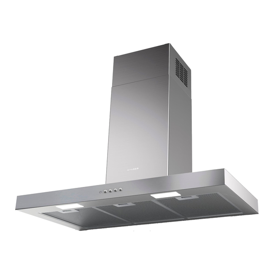
STILO
Wall Mount Canopy Rangehood
• Installation Instructions
• Use and Care Information
READ AND SAVE THESE INSTRUCTIONS
The Installer must leave these instructions with the homeowner.
The homeowner must keep these instructions for future reference
and for local electrical inspectors' use
.
Version 04/05 - Page 1
Table des Matières

Manuels Connexes pour Faber STILO Serie


Sommaire des Matières pour Faber STILO Serie
-
Page 11: Plan De Lʼinstallation
OUTILS NÉCESSAIRES À LʼINSTALLATION PLAN DE LʼINSTALLATION • Scie sauteuse ou à découper Cette hotte peut être installée avec ou sans conduit. La sortie dʼair peut • Perceuse sʼeffectuer par le mur ou le plafond. Pour une ventilation par le mur, un •... -
Page 12: Dimensions Dʼinstallation Avec Conduit
DIMENSIONS DʼINSTALLATION AVEC CONDUIT 1/8 po couvercle cheminée 1/8 po supérieure La cheminée Stilo est réglable pour différentes hauteurs de plafond, entre 7 pi 4 3/4 po et 8 pi 9 3/4 po 1/4 po couvercle cheminée (regardez la distance entre la hotte inférieure et la table de cuisson - X en FIGURE 4A). - Page 13 DIMENSIONS DʼINSTALLATION SANS CONDUIT 10 po min couvercle cheminée supérieure 1/8 po 1/4 po Pour installations sans conduit, la cheminée couvercle cheminée inférieure Stilo est réglable pour différentes hauteurs sans conduit de plafond, entre 7 pi 9 5/8 po et 8 pi 9 3/4 po (regardez la distance entre la hotte et la table de cuisson - X en FIGURE 4B).
-
Page 14: Préparation Du Mur
PRÉPARATION DU MUR INSTALLATION DE LA HOTTE 1. Retirer les filtres pour la graisse de lʼappareil et mettre de côté. 1. Débrancher et enlever la cuisinière afin dʼavoir un meilleur accès Lors de la dépose des filtres, tirer/faire tourner le bouton au mur arrière. -
Page 15: Pour Tout Les Installations
POUR TOUT LES INSTALLATIONS 1. Brancher le câble dʼalimentation sur la hotte. Attacher le fil blanc du câble dʼalimentation sur le fil blanc de la hotte avec une cosse. Attacher le fil noir du câble dʼalimentation au fil noir de la hotte avec une cosse. -
Page 16: Garantie Et Service
Faber garantit à lʼutilisateur-acheteur dʼorigine que les produits lʼinterrupteur soit hors circuit. Retirer les deux vis (de la Faber vendus neufs par nous sont sans vice de matériel et FIGURE 14). Retirer lʼampoule et la remplacer par une de main-dʼoeuvre dʼorigine pour une période dʼun an à partir nouvelle ampoule. -
Page 17: Changement Des Fusibles
CHANGEMENT DES FUSIBLES DIAGRAMME DE CÂBLAGE Fusible: modèle 5X20 5A 1. Enlever les filtres. 2. Enlever les vis en fixant le boite porte-fusibles. 3. Ouvrir le porte-fusibles. 4. Remplacer le fusible avec un autre du meme modèle. 5. Remplacer la boite porte-fusible et les filtres. •...