Publicité
Les langues disponibles
Les langues disponibles
Liens rapides
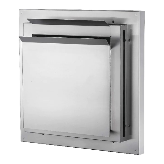
ST47U / ST58U-1
SAFETY INFORMATION
WARNING
!
FIRE OR EXPLOSION HAZARD
Failure to follow safety warnings exactly
could result in serious injury, death, or
property damage.
GENERAL INFORMATION
These installation instructions must be used in
conjunction with the appliance and appropriate
terminal kit installation instructions. Clearances
listed in these instructions supersede those in
the appliance's installation instructions.
Selecting and installing the appliance
When installing the Silhouette Terminal,
take into consideration the fi nish material
requirements and follow the relevant installation
instructions set out in this manual.
INSTALLER:
Leave this manual with the appliance
CONSUMER:
Retain this manual for future reference
Wolf Steel Ltd., 24 Napoleon Rd., Barrie, ON, L4M 0G8 Canada / 103 Miller Drive, Crittenden, Kentucky, USA, 41030
$10.00
ADD MANUAL TITLE
Phone 1 (866) 820-8686 • www.napoleon.com • hearth@napoleon.com
INSTALLATION
Silhouette Terminal
(MUST use title from Price Book)
ADD PRODUCT IMAGE
FOR USE ONLY WITH APPROVED
"FOR INDOOR USE ONLY" OR OTHER
4" / 7" AND 5" / 8"
DIRECT VENT GAS APPLIANCES
ENGLISH
FRENCH PG. 31
MANUAL
Product Name / Code
ADD ____ ILLUSTRATED
ST58U-1 illustrated
HORIZONTAL TERMINATION ONLY
APPLICABLE COMMENT
W415-2899 / A / 10.07.20
Publicité
Chapitres

Manuels Connexes pour Napoleon WOLF STEEL ST47U


Sommaire des Matières pour Napoleon WOLF STEEL ST47U
- Page 1 APPLICABLE COMMENT 4” / 7” AND 5” / 8” DIRECT VENT GAS APPLIANCES Wolf Steel Ltd., 24 Napoleon Rd., Barrie, ON, L4M 0G8 Canada / 103 Miller Drive, Crittenden, Kentucky, USA, 41030 Phone 1 (866) 820-8686 • www.napoleon.com • hearth@napoleon.com $10.00...
-
Page 2: Table Des Matières
il) ftalato (DEHP, por sus siglas en inglés), que el Estado de California reconoce como caus- antes de malformaciones congénitas u otros daños para la reproducción. Para obtener más información, visite www.P65Warnings.ca.gov. table of contents general information installation overview Gas, Wood list of certified appliances installation planning installation options... - Page 3 1.0 general information general information installation overview WARNING • FIRE HAZARD! Failure to comply with these installation instructions could result in serious damage. • Do NOT finish past the terminal return flange. For 4” / 7” appliances: For 5” / 8” appliances: Vinyl siding and Exterior finish material (less than Vinyl siding (less than 1”...
-
Page 4: General Information
general information list of certified appliances Product series MODEL B/CHD4ST Ascent Multi-view B/CHD4P B30/CB30 B35/CB35 Ascent B36/CB36/TB36 B42TR/CB42TR/TB42TR B46/CB46 BL36/CBL36 Ascent Linear BL46/CBL46 BHD4ST/CHD4ST Ascent Multi-View BHD4P/CHD4P Arlington GDS20/TDS20 Bayfield GDS25 Castlemore GDS26 Haliburton GDS28/CDVS280/TDS28 Havelock GDS/CDVS/TDS50 Knightsbridge GDS60/CDVS600/TDS60 GX36/CX36 Ascent X GX42 GX70/CX70... - Page 5 2.0 installation planning installation planning installation options TERMINAL STANDOFF BRICK STANDOFF There are multiple ways to install the Silhouette Terminal, based on the exterior finish material used. FOR USE WITH LISTED 4”/7” DIRECT VENT GAS APPLIANCES Brick Standoff Installation Type Terminal (ST47U) Standoff (SOST47) (SOST47B)
-
Page 6: Installation Planning
installation planning terminal overview WARNING • Do NOT finish past the terminal return flange. Failure to comply with these instructions could create a fire hazard. • Do NOT block the air intakes (all four sides) or the exhaust port. Ensure air flow within the terminal is not restricted in any way. -
Page 7: 4"/7" Terminal Dimensions
installation planning 2.2.1 4”/7” terminal dimensions FOR USE ONLY WITH APPROVED WOLF STEEL DIRECT VENT 4” / 7” GAS APPLIANCES front view right side view top view 9 41/64" 245mm 4 15/64" 108mm 14 1/64" 1 1/32" 356mm 26mm 14 29/32" 14 1/64"... -
Page 8: Terminal Kit Components
installation planning terminal kit components Reference Reference Part Number Description ST47U 4” / 7” SILHOUETTE TERMINAL ASSEMBLY ST58U-1 5” / 8” SILHOUETTE TERMINAL ASSEMBLY W570-0022 MOUNTING SCREWS (x4) W415-2899 / A / 10.07.20... -
Page 9: 4"/7" Standoff Dimensions
installation planning standoff overview 2.4.1 4”/7” standoff dimensions REQUIRED WITH 4”/7” TERMINAL (ST47U): EXTERIOR FINISH MATERIALS 1” (25MM) TO 2” (51mm) front view right side view top view 14 1/64" 356mm 10 1/2" 2" 267mm 51mm 14 47/64" 374mm 14 1/64" 356mm 10 1/2"... -
Page 10: 4"/7" Brick Standoff Dimensions
installation planning brick standoff overview 2.4.4 4”/7” brick standoff dimensions REQUIRED WITH 4”/7” TERMINAL (ST47U): FOR BRICK FOR VINYL SIDING BETWEEN 1” (25MM) AND 2” (51mm) front view right side view top view 14 1/64" 356mm 10 1/2" 267mm 4" 102mm 14 47/64"... -
Page 11: Brick Standoff Kit Components
installation planning standoff kit components Reference Reference Part Number Description SOST47 STANDOFF ASSEMBLY (4”/7”) SOST58 STANDOFF ASSEMBLY (5”/8”) W570-0022 SCREWS (x8) W570-0004 SCREWS (x4) brick standoff kit components Reference Reference Part Number Description SOST47B BRICK STANDOFF ASSEMBLY (4”/7”) SOST58B BRICK STANDOFF ASSEMBLY (5”/8”) W570-0022 SCREWS (x8) W570-0004... -
Page 12: Terminal Guard Overview
installation planning terminal guard overview Reference Reference Part Number Description STS4758 TERMINAL GUARD W570-0009 SCREWS (x4) W735-0011 WASHERS (x4) For applications where the terminal is situated in an accessible location, this kit MUST be installed, see “terminal auard installation (all)” section. W415-2899 / A / 10.07.20... - Page 13 3.0 terminal clearances terminal clearances TABLE 1: Minimum air terminal clearances (Canada / U.S.A) note: INSTALLATIONS Wall terminals are for illustration purposes only. Size and shapes may vary. CANADA U.S.A. 12” (30.5cm) Clearance above grade, veranda porch, deck or balcony. 12”...
- Page 14 terminal clearances TABLE 2: Silhouette terminal clearances (Canada / U.S.A) ST47U ST58U-1 Minimum soffit clearance 18” (non-vinyl wall, non-vinyl soffit) Minimum soffit clearance D, E 18” 20” (vinyl wall, non-vinyl soffit) Minimum soffit clearance 36” (all walls finishes, vinyl soffit) Maximum soffit length 9”...
- Page 15 4.0 pre-installation pre-installation firestop spacer installation WARNING • Use the firestop spacer provided with your appliance. • The firestop assembly must be installed with the vent shield to the top. This application occurs when venting through an exterior wall. Having determined the correct height for the termi- nation, cut and frame a hole in the exterior wall, as illustrated, to accommodate the firestop assembly.
- Page 16 5.0 installation installation WARNING • Minimum terminal and appliance clearance to combustibles must be maintained or a serious fire hazard could result. vinyl siding - less than 1” (25mm) (4”/7” only) Required (for 4”/7”): • Terminal (ST47U) Terminal (4”/7” only) 1.0 Attach the termination to the venting, see “pre-installation”...
- Page 17 installation Vinyl Firestop (Less than 1") assembly (4”/7” only) Firestop assembly Terminal important: The termination may be installed with the vinyl (less than 1” [25mm]) coming up to, but not past, the return flange of the termination. W415-2899 / A / 10.07.20...
- Page 18 installation vinyl siding - less than 1” (25mm) (5”/8” only) Standoff Required (for 5”/8”): • Terminal (ST58U-1) • Standoff (SOST58) 1.0 Place the standoff in the framed opening, using the tabs as guides. 2.0 Secure the standoff to the sheathing using the 8 long screws (supplied with standoff kit).
- Page 19 installation WARNING FOR 5”/8” ONLY: Applications with vinyl siding less than 1” (25mm) require a minimum 1” (25mm) • clearance from exterior vinyl siding to to the front edge of the return flange. Vinyl Firestop (Less than 1") assembly (5”/8” only) Standoff Firestop assembly...
- Page 20 installation vinyl siding - between 1” (25mm) and 2” (51mm) (all) Brick Standoff Required for 4”7”: • Terminal (ST47U) • Brick Standoff (SOST47B) Required for 5”/8”: • Terminal (ST58U-1) • Brick Standoff (SOST58B) 1.0 Place the standoff in the framed opening, using the tabs as guides.
- Page 21 installation WARNING • FOR 5”/8” ONLY: Applications with vinyl siding (1” (25mm) - 2” (51mm) require a minimum 2” (51mm) clearance from exterior vinyl siding to to the front edge of the return flange. Vinyl (1" - 2") Firestop assembly (4”/7”...
- Page 22 installation exterior finish material - less than 1” (25mm) (all) Terminal Required for 4”7”: • Terminal (ST47U) Required for 5”/8”: • Terminal (ST58U-1) 1.0 Attach the termination to the venting, see “pre-installation” and “venting” sections. note: All inner flex pipe and outer flex pipe joints to the termination may be sealed using high temperature red RTV silicone W573-0002 (not supplied) or the high temperature sealant W573-...
- Page 23 installation exterior finish material - between 1” (25mm) and 2” (51mm) (all) Standoff Required for 4”7”: • Terminal (ST47U) • Standoff (SOST47) Required for 5”/8”: • Terminal (ST58U-1) • Standoff (SOST58) 1.0 Place the standoff in the framed opening, using the tabs as guides. 2.0 Secure the standoff to the sheathing using the 8 long screws (supplied in standoff kit).
- Page 24 installation Exterior Finish Material Firestop assembly (1" - 2") (4”/7” and 5”/8”) Standoff Firestop assembly Terminal important: The termination may be installed with the exterior finish material (1” [25mm] to 2” [51mm]) coming up to, but not past, the return flange of the termination.
- Page 25 installation brick (all) WARNING If the thickness between the brick surface and sheathing exterior exceeds 4”, the brick must be installed after installing the brick standoff and BEFORE installing the termination. The termination cap will then secure to the surface of the brick and secure to the brick standoff. For non-standard brick sizes, it is recommended to either use a custom built brick standoff or mount the termination on the surface of the brick Required for 4”7”: •...
- Page 26 installation Firestop Brick assembly Brick Standoff Firestop assembly Terminal important: The termination may be installed with the brick coming up to, but not past, the return flange of the termination. W415-2899 / A / 10.07.20...
- Page 27 installation terminal guard installation (all) WARNING • This mesh guard is used to prevent against accidentally touching the Silhouette terminal when it is situated in an accessible location. The Silhouette terminal is considered accessible when it extends less than seven feet (7’) above grade, over a public sidewalk or a common driveway.
- Page 28 replacement parts WARNING • Failure to position the parts in accordance with this manual or failure to use only parts specifi cally approved with this appliance may result in property damage or personal injury. Contact your dealer for questions concerning prices and policies on replacement parts. Normally, all parts can be ordered through your Authorized dealer / distributor.
- Page 29 replacement parts 8.1 overview Ref. Part Number Description Stocked W585-0959 Exhaust Shield (ST47U) W585-0971 Exhaust Shield (ST58U-1) W415-2899 / A / 10.07.20...
- Page 30 NAPOLEON CELEBRATING OVER 40 YEARS OF HOME COMFORT PRODUCTS 7200, Route Transcanadienne, Montréal, Québec H4T 1A3 24 Napoleon Road, Barrie, Ontario, Canada L4M 0G8 214 Bayview Drive, Barrie, Ontario, Canada L4N 4Y8 103 Miller Drive, Crittenden, Kentucky, USA 41030 De Riemsdijk 22, 4004 LC Tiel, The Netherlands Phone: 1-866-820-8686 napoleon.com...
- Page 31 APPLICABLE COMMENT DIRECTE APPROUVÉ 4” / 7” ET 5” / 8” Wolf Steel Ltd., 24 Napoleon Rd., Barrie, ON, L4M 0G8 Canada / 103 Miller Drive, Crittenden, Kentucky, USA, 41030 Phone 1 (866) 820-8686 • www.napoleon.com • hearth@napoleon.com $10.00 W415-2899 / A / 10.07.20...
-
Page 32: This Product Can Expose You To Chemicals Including Wood Dust, Which Are
Gas, Wood table des matières WARNING: This product can expose you to chemicals including lead and lead compounds, information générale which are known to the State of California to cause cancer, and chemicals including carbon vue d’ensemble de l’installation monoxide, which are known to the State of California to cause birth defects or other reproduc- tive harm. -
Page 33: Vue D'ensemble De L'installation
1.0 information générale information générale vue d’ensemble de l’installation AVERTISSEMENT • RISQUE D’INCENDIE! Si ces instructions ne sont pas suivies à la lettre des dommages pourraient s’ensuivre. • Ne finis PAS au-délà la bride de retour de la terminaison. Pour les appareils d’évacuation 4” / 7”: Pour les appareils d’évacuation 5”... -
Page 34: Liste D'appareils Certifiés
information générale liste d’appareils certifiés Product series Modèle(s) MODEL Séries du produit B/CHD4ST Ascent Multi-view B/CHD4P B30/CB30 B35/CB35 Ascent B36/CB36/TB36 B42TR/CB42TR/TB42TR B46/CB46 BL36/CBL36 Ascent Linear BL46/CBL46 BHD4ST/CHD4ST Ascent Multi-View BHD4P/CHD4P Arlington GDS20/TDS20 Bayfield GDS25 Castlemore GDS26 Haliburton GDS28/CDVS280/TDS28 Havelock GDS/CDVS/TDS50 Knightsbridge GDS60/CDVS600/TDS60 GX36/CX36... - Page 35 2.0 planification de l’installation planification de l'installation options d’installation TERMINAL STANDOFF BRICK STANDOFF TERMINAISON ESPACEUR ESPACEUR DE BRIQUE Il y a multiple options d’installation possibles pour la Terminaison Silhouette, dépendant du matériau du finition utiliser sur le mur extérieur. POUR USAGE AVEC LES APPAREILS D’ÉVACUATION DIRECTE APPROUVÉ 4”/7” Terminaison Espaceur Espaceur de brique...
-
Page 36: Planification De L'installation
planification de l'installation vue d’ensemble de la terminaison AVERTISSEMENT • Ne finis PAS au-délà la bride de retour de la terminaison. Si ces instructions ne sont pas suivies à la lettre des dommages pourraient s’ensuivre. • Ne bloquer PAS les conduits d’entrées d’air (tous quatre côtés) ni le port d’échappement. Assurez-vous que la terminaison n’est pas restreinte d’aucune façon. -
Page 37: Dimensions De La Terminaison 5"/8
planification de l'installation 2.2.1 dimensions de la terminaison 4”/7” POUR USAGE AVEC LES APPAREILS D’ÉVACUATION DIRECTE APPROUVÉ 4”/7” DE WOLF STEEL vue de face vue de côté droite vue de dessus 9 41/64" 245mm 4 15/64" 108mm 14 1/64" 1 1/32" 356mm 26mm 14 29/32"... -
Page 38: Composants De L'ensemble De La Terminaison
planification de l'installation composants de l’ensemble de la terminaison Référence Référence No. de pièce Description ST47U ENSEMBLE DE LA TERMINAISON SILHOUETTE 4” / 7” ST58U-1 ENSEMBLE DE LA TERMINAISON SILHOUETTE 5” / 8” W570-0022 VIS DE MONTAGE (x4) W415-2899 / A / 10.07.20... -
Page 39: Dimensions De L'espaceur 4
planification de l'installation vue d’ensemble de l’espaceur 2.4.1 dimensions de l’espaceur 4”/7” REQUIS AVEC LA TERMINAISON 4”/7” (ST47U): POUR LES MATÉRIAUX DE FINITION EXTÉRIEUR 1” (25MM) À 2” (51MM) vue de face vue de côté droite vue de dessus 14 1/64" 356mm 10 1/2"... -
Page 40: Dimensions De L'espaceur De Brique 4
planification de l'installation vue d’ensemble de l’espaceur de brique 2.5.1 dimensions de l’espaceur de brique 4”/7” REQUIS AVEC LA TERMINAISON 4”/7” (ST47U): POUR BRIQUE POUR REVÊTEMENT EN VINYLE ENTRE 1” (25MM) ET 2” (51MM) vue de face vue de côté droite vue de dessus 14 1/64"... -
Page 41: Composants De L'ensemble De L'espaceur
planification de l'installation composants de l’ensemble de l’espaceur Référence Référence No. de pièce Description SOST47 ENSEMBLE DE L’ESPACEUR (4”/7”) SOST58 ENSEMBLE DE L’ESPACEUR (5”/8”) W570-0022 VIS (x8) W570-0004 VIS (x4) composants de l’ensemble de l’espaceur de brique Référence Référence No. de pièce Description SOST47B ENSEMBLE DE L’ESPACEUR DE BRIQUE (4”/7”) - Page 42 planification de l'installation vue d’ensemble de la garde de la terminaison Référence Référence No. de pièce Description STS4758 GARDE DE LA TERMINAISON W570-0009 VIS (x4) W735-0011 RONDELLES (x4) Pour les applications ou la terminaison est situé dans un location accessible, un ensemble de garde de la terminaison DOIT ÊTRE installé.
-
Page 43: Dégagements De La Terminaison
3.0 dégagements de la terminaison dégagements de la terminaison TABLEAU 1: Dégagements minimum de la terminaison (Canada / É.-U.) note: INSTALLATIONS Les terminaux du mur sont à des fi ns d’illustration seulement. La taille et les formes peuvent varier. CANADA É.-U. - Page 44 dégagements de la terminaison TABLEAU 2: Dégagement de la terminaison Silhouette (Canada / É.-U.) ST47U ST58U-1 Dégagement minimum de la soffite 18” (mur non vinyle, soffite non vinyle) Dégagement minimum de la soffite D, E 18” 20” (mur vinyle, soffite non vinyle) Dégagement minimum de la soffite 36”...
- Page 45 4.0 pré-installation pre-installation installation de l’espaceur coupe-feu AVERTISSEMENT • Utiliser l’espaceur coupe-feu fourni avec votre appareil. • L’espaceur coupe-feu doit être installé avec l’écran protecteur orienté vers le haut. Cette configuration s’applique lorsque le conduit d’évent traverse un mur extérieur. Une fois que vous aurez déterminé...
- Page 46 5.0 installation installation AVERTISSEMENT • Afin d’éviter un risque d’incendie grave, les dégagements minimaux aux matériaux combustibles de la terminaision et de l’appareil doivent être maintenus. revêtement en vinyle - moins de 1” (25mm) (uniquement 4”/7” ) Requis (pour 4”/7”): •...
-
Page 47: Installation
installation Revêtement en Vinyle (Moins de 1") (uniquement 4”/7”) Ensemble l'espaceur coupe-feu Terminaison important: La terminaison peut être installé avec le revêtement en vinyle (moins de 1” [25m]) jusqu’à, mais pas au-délà, la bride de retour de la terminaison. W415-2899 / A / 10.07.20... -
Page 48: Revêtement En Vinyle - Moins De 1" (25Mm) (Uniquement 5"/8")
installation revêtement en vinyle - moins de 1” (25mm) (uniquement 5”/8”) Espaceur Requis (pour 5”/8”): • Terminaison (ST58U-1) • Espaceur (SOST58) 1.0 Placez l’espaceur dans l’ouverture encadrée, à l’aide des onglets comme guides. 2.0 Fixez l’espaceur au revêtement à l’aide des 8 vis longs (fournies avec l’ensemble de l’espaceur). - Page 49 installation AVERTISSEMENT UNIQUEMENT POUR 5”/8” : Les applications avec le revêtement en vinyle requis un dégagement • minimum de 1” (25mm) de l’extérieur de revêtement en vinyle jusqu’au rebord avant de la bride de finition. Revêtement en Vinyle (Moins de 1") Espaceur (uniquement 5”/8”) Ensemble...
-
Page 50: Revêtement En Vinyle - Entre 1" (25Mm) Et 2" (51Mm) (Tous)
installation revêtement en vinyle - entre 1” (25mm) et 2” (51mm) (tous) Espaceur Requis pour 4”7”: • Terminaison (ST47U) de brique • Espaceur de brique (SOST47B) Requis pour 5”/8”: • Terminaison (ST58U-1) • Espaceur de brique (SOST58B) 1.0 Placez l’espaceur de brique dans l’ouverture encadrée, à... - Page 51 installation AVERTISSEMENT • UNIQUEMENT POUR 5”/8” : Les applications avec revêtement en vinyle requis un dégagement minimum de 2” (51mm) de l’extérieur de revêtement en vinyle jusqu’au rebord avant de la bride de finition. Revêtement en Vinyle (1" à 2") (4”/7”...
-
Page 52: Matériau De Finition Extérieur - Moins De 1" (25Mm) (Tous)
installation matériau de finition extérieur - moins de 1” (25mm) (tous) Terminaison Requis pour 4”7”: • Terminaison (ST47U) Requis pour 5”/8”: • Terminaison (ST58U-1) 1.0 Attachez la terminaison à l’évacuation, voir les sections « pré-installation » et « évacuation ». note: Tous les joints des conduits intérieurs et extérieurs à... -
Page 53: Matériau De Finition Extérieur - Entre 1" (25Mm) Et 2" (51Mm) (Tous)
installation matériau de finition extérieur - entre 1” (25mm) et 2” (51mm) (tous) Espaceur Requis pour 4”7”: • Terminaison (ST47U) • Espaceur (SOST47) Requis pour 5”/8”: • Terminaison (ST58U-1) • Espaceur (SOST58) 1.0 Placez l’espaceur dans l’ouverture encadrée, à l’aide des onglets comme guides. - Page 54 installation Matériau de finition extérieur (1" à 2") Espaceur (4”/7” et 5”/8”) Ensemble l'espaceur coupe-feu Terminaison important: La terminaison peut être installé avec le matériau de finition (entre 1” [25mm] et 2” [51mm]) jusqu’à, mais pas au-délà, la bride de retour de la terminaison.
- Page 55 installation brique (tous) AVERTISSEMENT Si l’épaisseur du surface de la brique et l’extérieur du revêtement dépassent 4”, la brique doit être installer après avoir installé l’espaceur de brique et AVANT d’installer la terminaison. Le capuchon de la terminaison sera ensuite fixer au surface de la brique et l’espaceur de brique.
-
Page 56: Brique (Tous)
installation Brique Espaceur de brique Ensemble l'espaceur coupe-feu Terminaison important: La terminaison peut être installé avec le brique jusqu’à, mais pas au-délà, la bride de retour de la terminaison. W415-2899 / A / 10.07.20... -
Page 57: Installation De La Garde De La Terminaison (Tous)
installation installation de la garde de la terminaison (tous) AVERTISSEMENT • La garde maillé est utiliser pour éviter contre toucher la terminaison Silhouette accidentellement lorsqu’elle est située dans un location accessible. La terminaison Silhouette est considérée accessible lorsqu’elle s’étend moins de 7 pieds au-dessus du niveau de sol, sur un troittoir public ou une allée commune. Install the terminal guard as illustrated. - Page 58 pièces de rechange pièces de rechange AVERTISSEMENT • Omettre de positionner les pièces conformément à ce manuel ou d’utiliser uniquement des pièces spécifi quement approuvées pour cet appareil peut causer des dommages matériels ou des blessures corporelles. Contactez votre détaillant pour les questions concernant les prix et la disponibilité des pièces de remplace- ment.
-
Page 59: Vue D'ensemble Note
pièces de rechange 8.1 vue d’ensemble Réf. No. de pièce Description En stock W585-0959 Bouclier d’échapppement (ST47U) W585-0971 Bouclier d’échapppement (ST58U-1) W415-2899 / A / 10.07.20... - Page 60 NAPOLÉON CÉLÈBRE PLUS DE 40 ANS D’EXISTENCE CONSACRÉS À LA CONCEPTION DE PRODUITS DE CONFORT 7200, Route Transcanadienne, Montréal, Québec H4T 1A3 24 Napoleon Road, Barrie, Ontario, Canada L4M 0G8 214 Bayview Drive, Barrie, Ontario, Canada L4N 4Y8 103 Miller Drive, Crittenden, Kentucky, USA 41030 De Riemsdijk 22, 4004 LC Tiel, Pays-Bas Téléphone: 1-866-820-8686...