
Manuels Connexes pour JUMO DELOS HP


Sommaire des Matières pour JUMO DELOS HP
- Page 1 JUMO DELOS HP Betriebsanleitung Operating Manual Notice de mise en service 40505400T90Z000K000 V1.00/DE-EN-FR/00645231...
- Page 3 JUMO DELOS HP Präzisions-Druckmessumformer mit Schaltkontakten und Anzeige Betriebsanleitung 40505400T90Z000K000 V1.00/DE/00645231...
-
Page 5: Table Des Matières
Inhalt Inhalt Sicherheitshinweise ..........5 Einleitung . - Page 6 Inhalt Inbetriebnahme ..........22 Schnelleinstieg .
-
Page 7: Sicherheitshinweise
Sicherheitshinweise 1 Sicherheitshinweise Allgemein Diese Anleitung enthält Hinweise, die Sie zu Ihrer eigenen Sicherheit sowie zur Vermeidung von Sach- schäden beachten müssen. Diese Hinweise sind durch Zeichen unterstützt und werden in dieser Anlei- tung wie gezeigt verwendet. Lesen Sie diese Anleitung, bevor Sie das Gerät in Betrieb nehmen. Bewahren Sie die Anleitung an ei- nem für alle Benutzer jederzeit zugänglichen Platz auf. -
Page 8: Einleitung
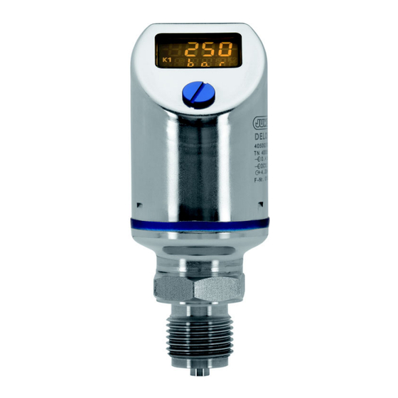
Einleitung 2 Einleitung Beschreibung Der hochpräzise, elektronische Druckmessumformer mit Schaltkontakten und Anzeige ist prädestiniert für den Einsatz an Prüfständen, Laborausstattungen sowie für den Sondermaschinenbau. Hier besteht oft die Forderung nach einer präzisen Messung und einer an die Messaufgabe angepassten Konfigura- tion. -
Page 9: Blockschaltbild
2 Einleitung Der Druck wird digital angezeigt. Der Messbereich lässt sich individuell konfigurieren. Je nach Ausführung stehen folgende Ausgänge zur Verfügung: • 1 PNP Schaltausgang • 2 PNP Schaltausgänge • 1 PNP Schaltausgang + 1 Analogausgang 4 bis 20 mA •... -
Page 10: Geräteausführung Identifizieren
Teile-Nummer Eingang Nennmessbereich Spannungsversorgung Ausgang Fertigungsnummer Herstelldatum (Jahr und Kalenderwoche) Bestellangaben Grundtyp 405054 JUMO DELOS HP – Präzisions-Druckmessumformer mit Schaltkontakten und Anzeige Grundtypergänzung ohne Sonderausführung Eingang 0 bis 160 bar Relativdruck 0 bis 600 bar Relativdruck Ausgang 1× PNP-Schaltausgang 2× PNP-Schaltausgang 1×... -
Page 11: Lieferumfang
öl- und fettfrei Dieses JUMO-Produkt ist unter amerikanischem und kanadischem Patent lizensiert. Käufer des JUMO-Produkts außerhalb der Vereinigten Staaten und Kanada sollen JUMO über vorgesehene Verkäufe der Produkte in die USA und nach Kanada informieren. Werkseinstellung: Der Analogausgang ist frei konfigurierbar. -
Page 12: Montage
Montage 4 Montage Allgemeines VORSICHT! Sachschaden Die Verträglichkeit des Gerätes mit dem Messmedium muss geprüft werden, siehe Kapitel 10 „Technische Daten“, Seite 39. Montageort • auf leichte Zugänglichkeit für die spätere Bedienung achten • Befestigung muss sicher und vibrationsarm sein •... -
Page 13: Gehäuse Drehen
4 Montage 4.1.2 Gehäuse drehen Das Gehäuse des Gerätes kann mit dem mitgelieferten Kombiwerkzeug (1) um ±160° gedreht werden. ±160° Abmessungen Typ 405054/000-... Ø 42 Prozessanschlüsse, nicht frontbündig G 1/2 1/4-18 NPT 20 Nm 30 Nm 1/4-18 NPT G 1/2... - Page 14 4 Montage G 1/4 G 1/2 20 Nm 20 Nm G 1/4 G 1/2 Profildichtung DN G 1/4 Profildichtung DN G 1/2 Prozessanschlüsse, frontbündig G 1/2 20 Nm Ø 18 G 1/2 Profildichtung DN G 1/2 O-Ring 15,1 × 1,6...
-
Page 15: Elektrischer Anschluss
Elektrischer Anschluss 5 Elektrischer Anschluss Installationshinweise GEFAHR! Personenschaden durch Stromschlag Der elektrische Anschluss darf nur von Fachpersonal vorgenommen werden! Die Lastkreise müssen auf die jeweils maximalen Lastströme abgesichert werden, um eine Zerstörung des Gerätes zu verhindern. Die Elektromagnetische Verträglichkeit entspricht EN 61326. An die Spannungsversorgung des Gerätes keine weiteren Verbraucher anschließen. -
Page 16: Farbbelegung Rundstecker M12 × 1
5 Elektrischer Anschluss Farbbelegung Rundstecker M12 × 1 VORSICHT! Sachschaden Die folgende Farbbelegung ist nur für A-codierte Standardkabel gültig! Farbbelegung: Anschlussleitung Rundstecker M12 × 1 1 BN Braun 2 WH Weiß 3 BU Blau 4 BK Schwarz 5 GY Grau Die Farbbelegung ist nur für A-codierte Standardkabel gültig! -
Page 17: Bedienen
Bedienen 6 Bedienen Bedienelemente Verschlussschraube Bedienelement 1. Verschlussschraube (1) abschrauben. 2. Bedienelement (2) mit beiliegendem Kombiwerkzeug (oder Schraubendreher 0,5 × 3 oder Innen- sechskantschlüssel SW2) „drehen/drücken“. LCD-Anzeige 6.2.1 Messmodus (Normalanzeige) Beispiel: Das Display leuchtet gelb. 6.2.2 Einstellmodus... -
Page 18: Ebenen
6 Bedienen Bedienung Weiter Kombiwerkzeug kürzer als 1 Sekunde drücken (< 1 s) Ja (übernehmen) Kombiwerkzeug kürzer als 1 Sekunde drücken (< 1 s) Nein (Abbruch) Kombiwerkzeug länger als 3 Sekunden drücken (> 3 s) Timeout keine Aktion für länger als 60 Sekunden (> 60 s) HINWEIS! Um vom Einstellmodus in den Messmodus zurückzukehren: - Nein (Abbruch) drücken oder... -
Page 19: Parameter
6 Bedienen Parameter 6.4.1 Eingang Parameter Anzeige Einstellbereich Einheit Druck (% siehe Kapitel 7.16 „Anzeige-Einheit einstellen (D.Uni)“, Seite 34) Offset ±20 % vom Messbereich (Nullpunktkorrektur) Hinweis: Automatische Offset-Korrektur siehe Kapitel 7.5 „Nullpunkt (Offset) einstellen (Off.P)“, Seite 25 Dämpfung 0,00 bis 99,99 s (Filterzeitkonstante) Die Dämpfung wirkt sich auf das Verhalten des Analogausgangs der Anzeige und auf die Schal-... -
Page 20: Binärausgang 1
6 Bedienen 6.4.3 Binärausgang 1 Parameter Anzeige Einstellbereich Schaltfunktion Hysterese Schließer (nur bei Schaltausgang) Hysterese Öffner Fenster Schließer Fenster Öffner siehe Kapitel 7.10 „Schaltfunktion einstellen (B.Fct)“, Seite 30 Schaltpunkt 0,00 bis 100,00 % vom Nennmessbereich (nur bei Schaltausgang) siehe Kapitel 7.10 „Schaltfunktion einstellen (B.Fct)“, Seite 30 Rückschaltpunkt 0,00 bis 100,00 % vom Nennmessbereich... -
Page 21: Anzeige Und Bedienung
6 Bedienen Parameter Anzeige Einstellbereich Schaltverzögerung 0,00 bis 99,99 s (nur bei 2. Schaltausgang) siehe Kapitel 7.10 „Schaltfunktion einstellen (B.Fct)“, Seite 30 Die Standardeinstellung ist fett markiert. 6.4.5 Anzeige und Bedienung Parameter Anzeige Einstellbereich Anzeigeposition Std = normal (für Normalbetrieb) turn = um 180°... - Page 22 6 Bedienen Anschluss DC 24 V Spannungsversorgung DC 24 V Druckschalter, Typ 405054 USB/TTL-Umsetzer, Notebook/PC Bestandteil von Teile-Nr. 00456352 4-polige Kabeldose (gerade), M12 × 1, mit 2 m PVC-Kabel, Teile-Nr. 00404585 oder 4-polige Winkeldose, M12 × 1, mit 2 m PVC-Kabel, Teile-Nr. 00409334 Verbindungsleitung, Teile-Nr.
-
Page 23: Setup-Programm Starten
6 Bedienen 6.5.2 Setup-Programm starten Start/Programme/JUMO-Geräte/Setup-Programm JUMO DELOS SI, HP DELOS SI, HP... - Page 24 Inbetriebnahme 7 Inbetriebnahme Schnelleinstieg HINWEIS! Das ist ein Vorschlag, damit das Gerät in kurzer Zeit zuverlässig konfiguriert werden kann. Wenn Sie die Einstellmöglichkeiten dieser Liste vor Beginn der Konfiguration prüfen, können „Timeouts“ während der Konfiguration vermieden werden. 1. Das Gerät montieren. ...
-
Page 25: Inbetriebnahme
7 Inbetriebnahme Gerät entriegeln (Code-Eingabe) Zum Schutz vor unbefugter Bedienung ist das Gerät mit einem Code geschützt. Der Code ist auf 0072 (Werkseinstellung) eingestellt. Er kann nur mit dem Setup-Programm geändert werden. Wird der Code mit dem Setup-Programm auf 0000 gesetzt, ist das Gerät ungeschützt. Entriegeln Verschlussschraube Kombiwerkzeug... -
Page 26: Bedienung Abbrechen
7 Inbetriebnahme Bedienung abbrechen 1. Kombiwerkzeug länger als 3 Sekunden drücken oder 2. „Timeout“ abwarten (keine Aktion länger als 60 Sekunden) Einheit des Messwertes wählen (Uni.P) 1. Gerät entriegeln. Kapitel 7.2 „Gerät entriegeln (Code-Eingabe)“, Seite 23 2. „Drehen“, bis die untere Zeile „Uni.P“ anzeigt. 3. -
Page 27: Nullpunkt (Offset) Einstellen (Off.p)
7 Inbetriebnahme Darstellungs- und Einstellmöglichkeiten des Gerätes Messbereich Einheit Anzeige Anfang Ende 0 bis 160 bar 160,0 0,00 16,00 2321 100,0 0 bis 600 bar 600,0 0,00 60,00 8702 100,0 Nullpunkt (Offset) einstellen (Off.P) 7.5.1 Automatische Offseteinstellung Mit dieser Einstellung wird der aktuelle Messwert als neuer Nullpunkt übernommen. 1. -
Page 28: Filterzeitkonstante (Dämpfung) Einstellen (Damp)
7 Inbetriebnahme Filterzeitkonstante (Dämpfung) einstellen (DamP) Mit der Filterzeitkonstanten (Dämpfung) kann der Messwert „beruhigt“ werden. Kleine Filterzeitkonstante: Der Messwert wird schneller aktualisiert. Große Filterzeitkonstante: Der Messwert wird langsamer aktualisiert. Der Wert wird in Sekunden mit zwei Nachkommastellen eingegeben. 1. Das Gerät entriegeln. ... -
Page 29: Skalierung Des Ausgangssignals Einstellen
7 Inbetriebnahme Skalierung des Ausgangssignals einstellen Kundenspezifische Skalierung Oft ist es wünschenswert, einen Teil des Nennmessbereiches auf das Ausgangssignal zu skalieren. Beispiel: Das Gerät hat einen Nennmessbereich (1) von 0 bis 160 bar und das Ausgangssignal 4 bis 20 mA (3). Soll Der Anwender wünscht: Sein „Messbereich Anwender“... -
Page 30: Anfangswert Der Skalierung Einstellen (Sc.lo)
7 Inbetriebnahme Nennmessbereich Messbereich Anwender Ausgangssignal Skalierung Anfang Skalierung Ende 7.8.1 Anfangswert der Skalierung einstellen (Sc.Lo) HINWEIS! Nur bei Geräten mit Analogausgang kann das Ausgangssignal skaliert werden! Einstellbereich: 0 bis 75 % des Nennmessbereiches Werkseinstellung: Messbereichsanfang Beispiel: Das Gerät hat einen Messbereich von 0 bis 160 bar. Das Ausgangssignal des Geräts ist 4 bis 20 mA. -
Page 31: Fehlersignal Einstellen
7 Inbetriebnahme 3. „Drücken“ (- blinkend, Sc.Lo fest) HINWEIS! Der Wert wird „Stelle für Stelle“ eingegeben! Fehlersignal einstellen (S.Err) HINWEIS! Nur bei Geräten mit Analogausgang wird bei Messbereichsüber- oder -unterschreitung ein Fehlersignal ausgegeben! Einstellen 1. Das Gerät entriegeln. Kapitel 7.2 „Gerät entriegeln (Code-Eingabe)“, Seite 23 2. -
Page 32: Schaltfunktion Einstellen (B.fct)
7 Inbetriebnahme 7.10 Schaltfunktion einstellen (B.Fct) 7.10.1 Hysterese (Schaltdifferenz) 1. Das Gerät entriegeln. Kapitel 7.2 „Gerät entriegeln (Code-Eingabe)“, Seite 23 2. „Drehen“, bis die untere Zeile „B.Fct“ anzeigt. 3. „Drücken“ Hysterese Schließer (no) (Schaltdifferenz) = oberer Grenzwert (Werkseinstellung) Hysterese Öffner (nc) (Schaltdifferenz) = unterer Grenzwert Verhalten des Relais •... -
Page 33: Fenster
7 Inbetriebnahme 7.10.2 Fenster Verhalten des Relais • Fensterfunktion Schließer (no) • Fensterfunktion Öffner (nc) Schaltpunkt (Sp) Rückschaltpunkt (RSp) Hysterese (Schaltdifferenz) Schließer (no) Öffner (nc) 1. Das Gerät entriegeln. Kapitel 7.2 „Gerät entriegeln (Code-Eingabe)“, Seite 23 2. „Drehen“, bis die untere Zeile „B.Fct“ anzeigt. 3. -
Page 34: Schaltpunkt Einstellen (B.sp)
7 Inbetriebnahme 7.11 Schaltpunkt einstellen (B.Sp) Kapitel 7.10 „Schaltfunktion einstellen (B.Fct)“, Seite 30 Einstellbereich: 0 bis 100 % des Nennmessbereiches Werkseinstellung: 50 % vom Nennmessbereich Einstellen 1. Das Gerät entriegeln. Kapitel 7.2 „Gerät entriegeln (Code-Eingabe)“, Seite 23 2. „Drehen“, bis die untere Zeile „B.Sp“ anzeigt. 3. -
Page 35: Schaltverzögerung Einstellen (B.dly)
0,00 bis 99,99 s Werkseinstellung: 0,00 s Einstellen Die Schaltverzögerung ist nicht bei jeder Schaltflanke wirksam. Gilt nur für JUMO DELOS SI und JUMO DELOS HP. 1. Das Gerät entriegeln. Kapitel 7.2 „Gerät entriegeln (Code-Eingabe)“, Seite 23 2. „Drehen“, bis die untere Zeile „B.DLY“ anzeigt. -
Page 36: Anzeige-Ausrichtung Einstellen (D.dir)
7 Inbetriebnahme 7.15 Anzeige-Ausrichtung einstellen (D.Dir) Einstellbereich: std = Standard = Gerät aufrecht turn = gedreht = Gerät über Kopf Werkseinstellung: Einstellen 1. Das Gerät entriegeln. Kapitel 7.2 „Gerät entriegeln (Code-Eingabe)“, Seite 23 2. „Drehen“, bis die untere Zeile „D.Dir“ anzeigt. 3. -
Page 37: Software-Version Des Bedienteils Anzeigen (Sw.di)
7 Inbetriebnahme Pro.2 = Der Messwert wird in Prozent des skalierten Messbereiches angezeigt, siehe Kapitel 7.8.1 „Anfangswert Skalierung einstellen (Sc.Lo)“, Seite 28 Kapitel 7.8.2 „Endwert der Skalierung einstellen (Sc.Hi)“, Seite 28 Beispiel: Der Messbereich des Gerätes wurde auf 0 bis 400 bar eingestellt, der skalierte Messbereich ist 400 bar. Wenn das Gerät einen Druck von 200 bar misst, so wird 50 % angezeigt. -
Page 38: Nullpunkt (Offset) Einstellen (Off.p)
7 Inbetriebnahme 7.19 Nullpunkt (Offset) einstellen (Off.P) 7.19.1 Automatische Offseteinstellung Am Gerät siehe Kapitel 7.5.1 „Automatische Offseteinstellung“, Seite 25 Per Setup-Programm nicht möglich 7.19.2 Editierte Offseteinstellung Am Gerät siehe Kapitel 7.19.2 „Editierte Offseteinstellung“, Seite 36 Per Setup-Programm 1. Das Gerät mit dem PC verbinden. 2. -
Page 39: Wartung, Reinigung Und Rücksendung
Bitte senden Sie bei Auffälligkeiten (Rückstände von Säuren, Laugen etc.) das Gerät mit einer ausge- füllten Dekontaminationserklärung, Angaben zur Anwendung und dem Messstoff an den Hersteller. Die Dekontaminationserklärung finden Sie auf unserer Homepage unter: http://www.jumo.de/de_DE/support/produktservice/reparaturdienst.html HINWEIS! Bitte demontieren Sie das Gerät nur im drucklosen und stromlosen Zustand. -
Page 40: Fehler Und Störungen Beheben
Fehler und Störungen beheben 9 Fehler und Störungen beheben Anzeige Mögliche Ursache Maßnahme • Messbereichsüber- oder -unter- Anderen Messbereich konfigurieren, schreitung siehe Kapitel 7.4 „Einheit des Mess- wertes wählen (Uni.P)“, Seite 24 • Fühlerbruch Gerätefehler: 1, 6, 7, 8: Gerät an Service zurück- senden, Anschrift siehe Rückseite •... -
Page 41: Technische Daten
Technische Daten 10 Technische Daten 10.1 Allgemein Referenzbedingungen DIN 16086 und DIN EN 60770 Sensorsystem Dünnfilm-Technologie zulässige Lastwechsel > 10 Millionen Lage Montagelage beliebig Kalibrationslage Gerät senkrecht stehend, Prozessanschluss unten Nullpunktkorrektur vor Ort oder über Setup möglich (20 % vom Nennmessbereich) Anzeige positiv beleuchtetes Display Ausrichtung... -
Page 42: Ausgang
10 Technische Daten 10.3 Ausgang Alle Analogausgänge in Dreileitertechnik; Schaltausgänge: Open-Collector, PNP-Schaltung Analogausgang Strom Ausgang 475 4 bis 20 mA und 1× PNP-Schaltausgang Ausgang 476 0 bis 20 mA und 1× PNP-Schaltausgang Spannung Ausgang 477 0 bis 10 V und 1× PNP-Schaltausgang Messbereichsskalierung (turn down) Sprungantwortzeit (Analogeingang) -
Page 43: Mechanische Eigenschaften
10 Technische Daten 10.4 Mechanische Eigenschaften Prozessanschluss Werkstoff Edelstahl 316 L Prozessdichtung Das Messsystem ist verschweißt und somit dichtungslos Sensor Werkstoff Edelstahl 630 Gehäuse Werkstoff Edelstahl 316 L Gewindehülse M12 × 1 Edelstahl 316 L Gehäusedichtung VMQ Silikon; FDA-konform Anzeige PA (Polyamid) Verschlussschraube des Bedie- nelementes... -
Page 44: Hilfsenergie
10 Technische Daten VORSICHT! Die für das Gerät angegebene Schutzart wird nur mit verschlossener Bedienöffnung (1) erreicht. 10.6 Hilfsenergie Hilfsenergie Spannungsversorgung U Nennspannung DC 24 V 0 bis 20 mA, Dreileiter (Ausgang DC 12 bis 30 V 476) 4 bis 20 mA, Dreileiter (Ausgang DC 12 bis 30 V 475) 0 bis 10 V, Dreileiter (Ausgang 477) DC 14 bis 30 V... - Page 46 JUMO GmbH & Co. KG Moritz-Juchheim-Straße 1 Technischer Support Deutschland: 36039 Fulda, Germany Telefon: +49 661 6003-715 Telefon: +49 661 6003-9135 Telefax: +49 661 6003-606 Telefax: +49 661 6003-881899 E-Mail: mail@jumo.net E-Mail: service@jumo.net Internet: www.jumo.net Lieferadresse: Mackenrodtstraße 14 36039 Fulda, Germany...
- Page 47 JUMO DELOS HP Precision Pressure Transmitter with Switching Contacts and Display Operating Manual 40505400T90Z000K000 V1.00/EN/00645231...
- Page 49 Contents Contents Safety information..........5 Introduction .
- Page 50 Contents Startup ............22 Quick introduction .
-
Page 51: Safety Information
Safety information 1 Safety information General information This manual contains information that must be observed in the interest of your own safety and to avoid material damage. This information is supported by symbols which are used in this manual as indicated. Please read this manual before starting up the device. -
Page 52: Introduction
Introduction 2 Introduction Description This high-precision electronic pressure transmitter with switching contacts and a display predestined for use on test benches, with laboratory equipment, and in special-purpose mechanical engineering. These areas frequently require precise measuring and a configuration adapted to the measurement task. The stainless steel sensor welded to the thin-film sensor features a high level of burst safety, which exceeds the measuring range up to 5x in part. -
Page 53: Block Diagram
2 Introduction The following outputs are available, depending on the version: • 1 PNP switching output • 2 PNP switching outputs • 1 PNP switching output + 1 analog output 4 to 20 mA • 1 PNP switching output + 1 analog output 0 to 20 mA •... -
Page 54: Identifying The Device Version
Serial number Date of manufacture (year and calendar week) Order details Basic type 405054 JUMO DELOS HP – Precision Pressure Transmitter with Switching Contacts and Display Basic type extension None Special version Input 0 bar to 160 bar relative pressure... -
Page 55: Scope Of Delivery
This JUMO product is licensed under United States and Canadian patents. Purchasers of the JUMO product out- side of the United States and Canada should advise JUMO of any planned sales of the product into the United States and Canada. -
Page 56: Mounting
Mounting 4 Mounting General information CAUTION! Damage to property Check that the device is compatible with the measurement medium, see chapter 10 "Technical data", page 39. Mounting site • Ensure that the device is easily accessible for the later operation •... -
Page 57: Rotating The Housing
4 Mounting 4.1.2 Rotating the housing The device housing can be turned through ±160° using the supplied combination tool (1). ±160° Dimensions Type 405054/000-... Ø 42 Process connections, not front-flush G 1/2 1/4-18 NPT 20 Nm 30 Nm 1/4-18 NPT G 1/2... - Page 58 4 Mounting G 1/4 G 1/2 20 Nm 20 Nm G 1/4 G 1/2 Profile seal DN G 1/4 Profile seal DN G 1/2 Process connections, front-flush G 1/2 20 Nm Ø 18 G 1/2 Profile seal DN G 1/2 O-ring 15.1 ×...
-
Page 59: Electrical Connection
Electrical connection 5 Electrical connection Installation notes DANGER! Injury to persons caused by electric shock The electrical connection must only be carried out by qualified personnel! Ensure that the fuses of the load circuits are suitable for the maximum load currents to avoid damage to the device. - Page 60 5 Electrical connection Color coding: connecting cable round plug M12 × 1 1 BN Brown 2 WH White 3 BU Blue 4 BK Black 5 GY Grey The color coding is only for A-coded standard cables!
-
Page 61: Operation
Operation 6 Operation Control elements Sealing screw Control element 1. Unscrew the sealing screw (1). 2. Use the supplied combination tool (or a 0.5 x 3 mm screwdriver or a size 2 Allen key) to "Turn/press" the operating element (2). LCD display 6.2.1 Measuring mode (normal display) -
Page 62: Levels
6 Operation Operation Next Press the combination tool for less than 1 second (<1 s) Yes (apply) Press the combination tool for less than 1 second (<1 s) No (cancel) Press the combination tool for more than 3 seconds (> 3 s) Timeout No action for more than 60 seconds (>60 s) NOTE! -
Page 63: Parameter
6 Operation Parameter 6.4.1 Input Parameter Display Setting range Unit of pressure (%, see chapter 7.16 "Setting the digital indicator (D.Uni)", page 34) Offset ±20% of the measuring range (zero point correction) Note: Automatic offset correction, see chapter 7.5 "Setting the zero point (offset) (Off.P)", page 25 Damping 0.00 to 99.99 s... -
Page 64: Binary Output 1
6 Operation 6.4.3 Binary output 1 Parameter Display Setting range Switching function Closing hysteresis (only with switching output) Opening hysteresis Normally open contact window Normally closed contact window see chapter 7.10 "Setting the switching function (B.Fct)", page 30 Switching point 0.00 to 100.00% of the nominal measuring range (only with switching output) see chapter 7.10 "Setting the switching function... -
Page 65: Display And Operation
6 Operation Parameter Display Setting range Switching delay 0.00 to 99.99 s (only with 2nd. switching out- see chapter 7.10 "Setting the switching function put) (B.Fct)", page 30 The default setting is highlighted in bold. 6.4.5 Display and operation Parameter Display Setting range Display position... - Page 66 6 Operation Connection DC 24 V Voltage supply DC 24 V Pressure switch, type 405054 USB/TTL converter Laptop/PC included in part no. 00456352 4-pin cable box (straight) M12 × 1 with 2 m PVC cable, part no. 00404585 or 4-pin angled socket M12 x 1 with 2 m PVC cable, part no. 00409334 Transmitter cable, part no.
-
Page 67: Start The Setup Program
6 Operation 6.5.2 Start the setup program Start/Programs/JUMO devices/Setup program JUMO DELOS SI, HP DELOS SI, HP... -
Page 68: Startup
Startup 7 Startup Quick introduction NOTE! This is a proposal to be able to configure the device reliably within a short time. When checking the set- ting possibilities specified in this list prior to starting configuration, timeouts can be avoided during con- figuration. -
Page 69: Unlocking The Device (Enter The Code)
7 Startup Unlocking the device (enter the code). The device is protected against unauthorized operation by a code. Code is set to 0072 (factory setting). Changes are only possible with the setup program. The device will become unprotected when the setup program is used to set the code to 0000. Unlocking Sealing screw Combination tool... -
Page 70: Cancel Operation
7 Startup Cancel operation 1. Press the combination tool for more than 3 seconds or 2. wait for a "timeout" (no actions for more than 60 seconds) Select the unit of measured (Uni.P) 1. Unlock the device. chapter 7.2 "Unlocking the device (enter the code).", page 23 2. -
Page 71: Setting The Zero Point (Offset) (Off.p)
7 Startup Display and setting possibilities of the device Measuring range Unit Display Start 0 to 160 bar 160.0 0.00 16.00 2321 100.0 0 to 600 bar 600.0 0.00 60.00 8702 100.0 Setting the zero point (offset) (Off.P) 7.5.1 Automatic offset setting This setting applies the current measured value as the new zero point. -
Page 72: Setting The Filter Time Constant (Damping) (Damp)
7 Startup Setting the filter time constant (damping) (DamP) The filter time constants (damping) can be used to "damp" the measured value. Small filter time constant: The measured value is updated faster. Large filter time constant: The measured value is updated slower. The value is entered in seconds with two decimal places. -
Page 73: Setting The Output Signal Scaling
7 Startup Setting the output signal scaling Customer specific scaling It is frequently desirable to scale a part of the nominal measuring range to the output signal. Example: Actual The device has a nominal measuring range (1) 0 to 160 bar and the output signal is 4 to 20 mA (3). Set point Customer requirement: The "customer measuring range"... -
Page 74: Setting The Scaling Start Value (Sc.lo)
7 Startup Nominal measuring range Customer measuring range Output signal Scaling start Scaling end 7.8.1 Setting the scaling start value (Sc.Lo) NOTE! The output signal can only be scaled on devices with analog output. Setting range: 0 to 75% of the nominal measuring range Default setting: Measuring range start Example:... -
Page 75: Setting The Error Signal
7 Startup 3. "Press" (- flashing, Sc.Lo static) NOTE! The value is entered "digit-by-digit“! Setting the error signal (S.Err) NOTE! An error signal for overrange or underrange is only transmitted on devices with analog output. Setting 1. Unlock the device. ... -
Page 76: Setting The Switching Function (B.fct)
7 Startup 7.10 Setting the switching function (B.Fct) 7.10.1 Hysteresis (switching differential) 1. Unlock the device. chapter 7.2 "Unlocking the device (enter the code).", page 23 2. "Turn" until "B.Fct" appears in the bottom line. 3. "Press" Hysteresis normally open contact (switching differential) = upper limit value (default setting) Hysteresis (normally closed contact) (switching differential) = lower limit value Relay behavior •... -
Page 77: Window
7 Startup 7.10.2 Window Relay behavior • Window Function, N/O Contact • Window Function, N/C Contact Switching point (Sp) Release point (RSp) Hysteresis (switching differential) N/O contact N/C contact 1. Unlock the device. chapter 7.2 "Unlocking the device (enter the code).", page 23 2. -
Page 78: Setting The Switching Point (B.sp)
7 Startup 7.11 Setting the switching point (B.Sp) chapter 7.10 "Setting the switching function (B.Fct)", page 30 Setting range: 0 to 100% of the nominal measuring range Default setting: 50% of the nominal measuring range Setting 1. Unlock the device. ... -
Page 79: Setting The Switching Delay (B.dly)
Default setting: 0.00 s Setting The switching delay is not effective for all switching edges. Only applies for JUMO DELOS SI and JUMO DELOS HP. 1. Unlock the device. chapter 7.2 "Unlocking the device (enter the code).", page 23 2. -
Page 80: Setting The Display Alignment (D.dir)
7 Startup 7.15 Setting the display alignment (D.Dir) Setting range: std = Standard = Device vertical turn = rotated = Device overhead Default setting: Setting 1. Unlock the device. chapter 7.2 "Unlocking the device (enter the code).", page 23 2. -
Page 81: Displaying The Software Version Of The Operating Unit (Sw.di)
7 Startup Pro.2 = The measured value is displayed as a percentage of the scaled measuring range, , see chapter 7.8.1 "Setting the scaling start value (Sc.Lo)", page 28 and chapter 7.8.2 "Setting the scaling end value (Sc.Hi)", page 28 Example: The measuring range of the device has been set to 0 to 400 bar;... -
Page 82: Setting The Zero Point (Offset) (Off.p)
7 Startup 7.19 Setting the zero point (offset) (Off.P) 7.19.1 Automatic offset setting On the device siehe chapter 7.5.1 "Automatic offset setting", page 25 Using the setup program nicht möglich 7.19.2 Edited offset setting On the device siehe chapter 7.19.2 "Edited offset setting", page 36 Using the setup program 1. -
Page 83: Maintenance, Cleaning And Returns
In case of abnormalities (acid, lye residues, etc.), please send the device with a completed declaration of decontamination, and details of the application and the medium to the manufacturer. You will find the declaration of decontamination on our website at: http://www.jumo.de/de_DE/support/produktservice/reparaturdienst.html NOTE! Please only remove the device in a depressurized and zero-current state. -
Page 84: Overcoming Errors And Malfunctions
Overcoming errors and malfunctions 9 Overcoming errors and malfunctions Display Possible cause Measure • Measuring range overflow or un- Configuring another measuring derflow range, see chapter 7.4 "Select the unit of measured (Uni.P)", page 24 • Probe break Device error: 1, 6, 7, 8: Return device to Service;... -
Page 85: Technical Data
Technical data 10 Technical data 10.1 General Information Reference conditions DIN 16086 and DIN EN 60770 Sensor system Thin-film technology Admissible load changes > 10 million Position Mounting position Calibration position Device upright, process connection at the bottom Zero point correction Possible on-site or through setup (20% of nominal measuring range) Display Positively-lit display... -
Page 86: Output
10 Technical data 10.3 Output All analog outputs in three-wire connection; switching outputs: open collector, PNP circuit Analog output Current Output 475 4 to 20 mA and 1x PNP switching output Output 476 0 to 20 mA and 1x PNP switching output Voltage Output 477 0 to 10 V and 1x PNP switching output... -
Page 87: Mechanical Features
10 Technical data 10.4 Mechanical features Process connection Material Stainless steel 316 L Process seal The measuring system is welded and therefore entirely free of seals Sensor Material Stainless steel 630 Housing Material Stainless steel 316 L Threaded sleeve M12 x 1 Stainless steel 316 L Housing seal VMQ silicone;... -
Page 88: Auxiliary Power
10 Technical data 10.6 Auxiliary power Auxiliary energy Voltage supply U Nominal voltage DC 24 V 0 to 20 mA, three-wire (output 476) DC 12 to 30 V 4 to 20 mA, three-wire (output 475) DC 12 to 30 V 0 to 10 V, three-wire (output 477) DC 14 to 30 V Dropping below the admissible volt-... - Page 90 JUMO GmbH & Co. KG JUMO Instrument Co. Ltd. JUMO Process Control, Inc. Street address: JUMO House 6733 Myers Road Moritz-Juchheim-Straße 1 Temple Bank, Riverway East Syracuse, NY 13057, USA 36039 Fulda, Germany Harlow, Essex CM 20 2DY, UK Delivery address:...
- Page 91 JUMO DELOS HP Convertisseur de pression de précision avec contacts de commutation et affichage Notice de mise en service 40505400T90Z000K000 V1.00/FR/00645231...
- Page 93 Sommaire Sommaire Instructions relatives à la sécurité ....... . . 5 Introduction .
- Page 94 Sommaire Mise en service ..........22 Prise en main rapide .
-
Page 95: Instructions Relatives À La Sécurité
Instructions relatives à la sécurité 1 Instructions relatives à la sécurité Généralités Cette notice contient des instructions dont vous devez tenir compte aussi bien pour assurer votre propre sécurité que pour éviter des dégâts matériels. Ces instructions sont appuyées par des pictogrammes et sont utilisées dans cette notice comme indiqué. -
Page 96: Introduction
Introduction 2 Introduction Description Le convertisseur de pression électronique de haute précision avec contacts de commutation et affichage est prédestiné à être utilisé avec du matériel de laboratoire ainsi que pour la construction de machines spéciales. Une mesure précise est souvent exigée ainsi qu'une configuration adaptée à la tâche de me- sure. -
Page 97: Synoptique
2 Introduction Les sorties suivantes sont disponibles, suivant l'exécution : • 1 sortie de commutation PNP • 2 sorties de commutation PNP • 1 sortie de commutation PNP + 1 sortie analogique 4 à 20 mA • 1 sortie de commutation PNP + 1 sortie analogique 0 à 20 mA •... -
Page 98: Identification De L'exécution De L'appareil
Sortie Numéro de série Date de fabrication (année/semaine) Références de commande Type de base 405054 JUMO DELOS HP - Convertisseur de pression de précision avec contacts de commutation et affichage Extension du type de base Sans Exécution spéciale Entrée 0 à 160 bar pression relative 0 à... -
Page 99: Matériel Livré
Ce produit JUMO est distribué sous brevet américain et canadien. Les acheteurs de ce produit JUMO en dehors des Etats-Unis et du Canada doivent informer JUMO s'ils prévoient de vendre ce produit aux USA et au Canada. Réglage d'usine : la sortie analogique est librement configurable. -
Page 100: Montage
Montage 4 Montage Généralités ATTENTION! Dégât matériel La compatibilité de l'appareil avec le milieu doit être vérifiée, voir chapitre 10 "Caractéristiques tech- niques", page 39. Lieu de montage • Veiller à ce que l'appareil soit facilement accessible • La fixation doit être fiable et peu soumise aux vibrations. •... -
Page 101: Faire Pivoter Le Boîtier
4 Montage 4.1.2 Faire pivoter le boîtier Le boîtier de l'appareil peut pivoter de ±160° à l'aide de l'outil multifonction fourni (1). ±160° Dimensions Type 405054/000-... Ø 42 Raccords de process, non affleurants G 1/2 1/4-18 NPT 20 Nm 30 Nm 1/4-18 NPT G 1/2... - Page 102 4 Montage G 1/4 G 1/2 20 Nm 20 Nm G 1/4 G 1/2 Joint hydraulique DN 1/4"G Joint hydraulique DN 1/2"G Raccords de process, affleurants G 1/2 20 Nm Ø 18 G 1/2 Joint hydraulique DN 1/2"G Joint torique 15,1 × 1,6...
-
Page 103: Raccordement Électrique
Raccordement électrique 5 Raccordement électrique Instructions relatives à l’installation DANGER! Dommage corporel par décharge électrique Le raccordement électrique ne peut être effectué que par du personnel qualifié ! Les circuits de charge doivent être protégés par un fusible pour les courants de charge max. respectifs afin d'empêcher la destruction de l'appareil. - Page 104 5 Raccordement électrique Repérage des couleurs : 1 BN Brun câble de raccordement connecteur coaxial M12 × 1 2 WH Blanc 3 BU Bleu 4 BK Noir 5 GY Gris Le repérage des couleurs est uniquement valable pour le câble standard codé A !
-
Page 105: Commander
Commander 6 Commander Eléments de commande Bouchon fileté Elément de commande 1. Dévisser le bouchon fileté (1) 2. „Appuyer/Tourner“ l'élément de commande (2) avec l'outil multifonction fourni (ou tournevis 0,5 x 3 ou clé mâle coudé pour vis à 6 pans OC2) Ecran LCD 6.2.1 Mode mesure (affichage normal) -
Page 106: Niveaux
6 Commander Commande Suivant Appuyer sur l’outil moins d’1 seconde (< 1 s) Oui (valider) Appuyer sur l’outil moins d’1 seconde (< 1 s) Non (annuler) Appuyer sur l’outil plus de 3 secondes (> 3 s) Timeout Aucune action plus de 60 secondes (> 60 s) REMARQUE ! Pour passer du mode réglage au mode mesure : - Non (Annuler) ou... -
Page 107: Aperçu Des Paramètres
6 Commander Aperçu des paramètres 6.4.1 Entrée Paramètre Affichage Plage de réglage Unité Pression (% voir chapitre 7.16 "régler l'unité d'affichage (D.Uni)", page 34) Offset ±20 % de l'étendue de mesure (correction du zéro) Remarque : correction de l'offset automatique voir chapitre 7.5 "Régler le point zéro (offset) (Off.P)", page 25 Amortissement... -
Page 108: Sortie Binaire 1
6 Commander 6.4.3 Sortie binaire 1 Paramètre Affichage Plage de réglage Fonction de commutation Hystérésis A fermeture (uniquement si sortie de com- Hystérésis A ouverture mutation) Fenêtre A fermeture Fenêtre A ouverture voir chapitre 7.10 "Régler la fonction de commuta- tion (B.Fct)", page 30 Fonction de commutation 0,00 à... -
Page 109: Anffichage Et Commande
6 Commander Paramètre Affichage Plage de réglage Temporisation 0,00 à 99,99 s (uniquement pour seconde voir chapitre 7.10 "Régler la fonction de commuta- sortie de commutation) tion (B.Fct)", page 30 Le réglage standard est en gras. 6.4.5 Anffichage et commande Paramètre Affichage Plage de réglage... - Page 110 6 Commander Raccordement DC 24 V Alimentation 24 V DC Pressostat, type 405054 Convertisseur USB/TTL, Portable / PC composant de la référence article 00456352 Connecteur à 4 pôles (droit) M12 × 1 avec 2 m de câble PVC, référence article 00404585 ou connecteur coudé...
-
Page 111: Démarrer Le Programme Setup
6 Commander 6.5.2 Démarrer le programme Setup. Start/Programme/Appareils JUMO/Programme Setup JUMO DELOS SI, HP DELOS SI, HP... -
Page 112: Mise En Service
Mise en service 7 Mise en service Prise en main rapide REMARQUE ! Proposition pour une configuration rapide et fiable de l’appareil. Si vous testez les possibilités de cette liste avant de commencer la configuration, des temps morts „time out“ pourront être évités pendant la configuration. -
Page 113: Déverrouiller L'appareil (Saisie Du Code)
7 Mise en service Déverrouiller l’appareil (saisie du code) L’appareil est protégé par un code pour éviter toute manipulation non autorisée Le code est réglé sur 0072 (réglage d'usine). Il peut seulement être modifié à l'aide du logiciel. Lorsque le code est réglé à 0000 avec le programme Setup, l’appareil n’est pas protégé. Déverrouiller Bouchon fileté... -
Page 114: Annuler La Commande
7 Mise en service Annuler la commande 1. Appuyer plus de 3 secondes sur l'outil multifonction ou 2. attendre le temps mort „time out“ (pas d'action supérieure à 60 secondes). Sélectionner l'unité de la valeur mesurée (Uni.P) 1. Déverrouiller l'appareil. ... -
Page 115: Régler Le Point Zéro (Offset) (Off.p)
7 Mise en service Possibilités de réglage et de représentation de l'appareil Etendue de mesure Unités Affichage Début 0 à 160 bar 160,0 0,00 16,00 2321 100,0 0 à 600 bar 600,0 0,00 60,00 8702 100,0 Régler le point zéro (offset) (Off.P) 7.5.1 Réglage automatique de l'offset Avec ce réglage, la valeur mesurée actuelle est prise en compte comme nouveau point zéro. -
Page 116: Régler La Constante De Temps Du Filtre (Amortissement) (Damp)
7 Mise en service Régler la constante de temps du filtre (amortissement) (DamP) La constante de temps du filtre (amortissement) permet de „stabiliser“ la valeur mesurée. Petite constante de temps du filtre : la valeur mesurée est actualisée plus rapidement. Grande constante de temps du filtre : la valeur mesurée est actualisée plus lentement. -
Page 117: Régler La Mise À L'échelle Du Signal De Sortie
7 Mise en service Régler la mise à l'échelle du signal de sortie Mise à l'échelle spécifique Il est souvent souhaitable qu’une partie de l’étendue de mesure soit mise à l’échelle sur le signal de sortie. Exemple : Prévu(e) Etendue de mesure de l'appareil comprise (1) entre 0 et 160 bar et du signal de sortie 4 à 20 mA (3). Réel(le) Le client souhaite : son „étendue de mesure utilisateur“... -
Page 118: Régler La Valeur Initiale De La Mise À L'échelle (Sc.lo)
7 Mise en service Etendue de mesure nominale Etendue de mesure Utilisateur Signal de sortie Début de mise à l'échelle Fin de mise à l'échelle 7.8.1 Régler la valeur initiale de la mise à l'échelle (Sc.Lo) REMARQUE ! Le signal de sortie peut être mis à l’échelle seulement pour les appareils disposant d’une sortie analo- gique ! Plage de réglage : 0 à... -
Page 119: Régler Le Signal D'erreur
7 Mise en service 1. Déverrouiller l'appareil chapitre 7.2 "Déverrouiller l’appareil (saisie du code)", page 23 2. „Tourner“, jusqu'à ce ce que la ligne du bas affiche „Sc.Hi“. 3. „Appuyer“ (- clignote, Sc.Lo, Uni.P fixe) REMARQUE ! La valeur est saisie „digit par digit“ ! Régler le signal d'erreur (S.Err) REMARQUE ! Seuls les appareils avec sortie analogique émettent un signal d’erreur en cas de dépassement inférieur/... -
Page 120: Régler La Fonction De Commutation (B.fct)
7 Mise en service 7.10 Régler la fonction de commutation (B.Fct) 7.10.1 Hystérésis (différentiel de coupure) 1. Déverrouiller l'appareil chapitre 7.2 "Déverrouiller l’appareil (saisie du code)", page 23 2. „Tourner“, jusqu'à ce que la ligne du bas affiche „B.Fct“. 3. -
Page 121: Fenêtre
7 Mise en service 7.10.2 Fenêtre Comportement du relais • Fonction fenêtre à fermeture (no) • Fonction fenêtre à ouverture (nc) Point de commutation (Sp) Position de retour (RSp) Hystérésis (différentiel de coupure) À fermeture (no) À ouverture (nc) 1. Déverrouiller l'appareil ... -
Page 122: Régler Le Point De Commutation (B.sp)
7 Mise en service 7.11 Régler le point de commutation (B.Sp) chapitre 7.10 "Régler la fonction de commutation (B.Fct)", page 30 Plage de réglage : 0 à 100 % de l'étendue de mesure nominale Réglage d’usine : 50 % de l'étendue de mesure nominale Régler 1. -
Page 123: Régler La Temporisation (B.dly)
0,00 à 99,99 s Réglage d’usine : 0,00 s Régler La temporisation n'est pas efficace pour chaque front de commutation. Valable uniquement pour JUMO DELOS SI et JUMO DELOS HP. 1. Déverrouiller l'appareil chapitre 7.2 "Déverrouiller l’appareil (saisie du code)", page 23 2. -
Page 124: Régler L'orientation De L'affichage (D.dir)
7 Mise en service 7.15 Régler l'orientation de l'affichage (D.Dir) Plage de réglage : Std = Standard = appareil droit turn = tourné= appareil tête en bas Réglage d’usine : Régler 1. Déverrouiller l'appareil chapitre 7.2 "Déverrouiller l’appareil (saisie du code)", page 23 2. -
Page 125: Afficher Le Version Logicielle De La Partie Commande (Sw.di)
7 Mise en service Pro.2 = la valeur mesurée est affichée en pourcentage de l’étendue de mesure mise à l'échelle, voir chapitre 7.8.1 "Régler la valeur initiale de la mise à l'échelle (Sc.Lo)", page 28 et chapitre 7.8.2 "Régler la valeur finale de l'échelle (Sc.Hi)", page 28 Exemple : L'étendue de mesure de l'appareil a été... -
Page 126: Régler Le Point Zéro (Offset) (Off.p)
7 Mise en service 7.19 Régler le point zéro (offset) (Off.P) 7.19.1 Réglage automatique de l'offset Sur l'appareil siehe chapitre 7.5.1 "Réglage automatique de l'offset", page 25 Via le programme Setup nicht möglich 7.19.2 Réglage de l'offset paramétré Sur l'appareil siehe chapitre 7.19.2 "Réglage de l'offset paramétré", page 36 Via le programme Setup 1. -
Page 127: Entretien, Nettoyage Et Retour
En cas de panne (résidus d'acide, d'alcalis, etc.) veuillez nous retourner l’appareil avec la déclaration de décontamination et des indications concernant le milieu de mesure. Vous trouverez la déclaration de décontamination sur notre page d'accueil sous : http://www.jumo.fr/fr_FR/support/services/service-reparation.html REMARQUE ! Veuillez uniquement démonter l'appareil hors tension et hors pression. -
Page 128: Suppression Des Défauts Et Perturbations
Suppression des défauts et perturbations 9 Suppression des défauts et perturbations Affichage Cause possible Mesure • Dépassement inférieur ou supé- Configurer l'autre étendue de me- rieur de l'étendue de mesure sure, voir chapitre 7.4 "Sélectionner l'unité de la valeur mesurée (Uni.P)", •... -
Page 129: Caractéristiques Techniques
Caractéristiques techniques 10 Caractéristiques techniques 10.1 Généralités Normes de référence DIN 16086 et EN 60770 Système du capteur Technologie à couche mince Cycles d'effort admissibles > 10 millions Position Position de montage Quelconque Position de calibrage Appareil à la verticale, raccord de process vers le bas Correction du zéro sur site ou via le Setup (20 % de l'étendue de mesure nominale). -
Page 130: Sortie
10.3 Sortie 10 Caractéristiques techniques Toutes les sorties analogiques en technique 3 fils/sorties de commutation : à collecteur ouvert, montage Sortie analogique Courant Sortie 475 4 à 20 mA et 1 × sortie de commutation PNP Sortie 476 4 à 20 mA et 1 × sortie de commutation PNP Tension Sortie 477 0 à... -
Page 131: Propriétés Mécaniques
10 Caractéristiques techniques 10.4 Propriétés mécaniques Raccordement au process Matériau Acier inoxydable AISI 316 Ti Joint de process Le système de mesure est soudé et donc sans joint. Capteur Matériau Acier inoxydable 630 Boîtier Matériau Acier inoxydable AISI 316 Ti Raccord M12 ×... -
Page 132: Energie Auxiliaire
10 Caractéristiques techniques ATTENTION! Le mode de protection indiqué pour l'appareil n'est atteint qu'avec ouverture d'accès fermée. 10.6 Energie auxiliaire Energie auxiliaire Alimentation U Tension nominale 24 V DC 0 à 20 mA, 3 fils (sortie 476) 12 à 30 V DC 4 à... - Page 134 JUMO GmbH & Co. KG Adresse : Moritz-Juchheim-Straße 1 36039 Fulda, Allemagne Adresse de livraison : Mackenrodtstraße 14 36039 Fulda, Allemagne Adresse postale : 36035 Fulda, Allemagne Téléphone : +49 661 6003-0 Télécopieur : +49 661 6003-607 E-Mail: mail@jumo.net Internet: www.jumo.net...