Publicité
Liens rapides
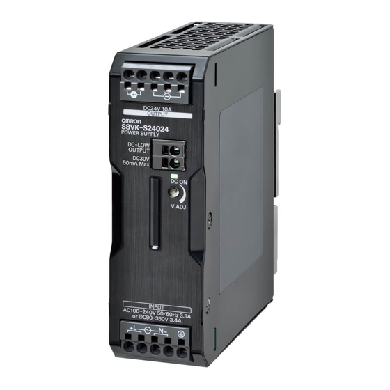
S8VK-S
MODEL
SWITCHING
POWER SUPPLY
EN
INSTRUCTION MANUAL
Bedienungsanleitung
DE
Manuel d'instructions
FR
Thank you for purchasing the S8VK-S.
This Instruction Manual describes the functions, performance, and application methods
understanding.
Keep this Instruction Manual close at hand and use it for reference during operation.
Herzlichen Glückwunsch zum Kauf des S8VK-S.
Diese Bedienungsanleitung beschreibt die Funktionen, Leistungen und Anwendungsmethoden,
die für den Betrieb des S8VK-S erforderlich sind.
Vergewissern Sie sich, dass das S8VK-S von Elektro-Fachleuten bedient wird.
Lesen Sie diese Bedienungsanleitung sorgfältig durch und vergewissern Sie sich vor
dem Betrieb, alles verstanden zu haben.
Heben Sie die Bedienungsanleitung griffbereit auf und nutzen Sie sie während des
Betriebs als Referenz.
Ce manuel d'instructions apporte une description des fonctions, des performances et des
méthodes d'application nécessaires à son utilisation.
chargé de sa manipulation.
Veuillez lire attentivement ce manuel d'instructions et vous assurer d'avoir bien
compris le fonctionnement de l'appareil avant de l'utiliser.
Gardez ce manuel à portée de main et utilisez-le comme référence pendant son utilisation.
OMRON Corporation
SHIOKOJI HORIKAWA, Shimogyo-Ku, Kyoto, 600-8530 Japan
©All Rights Reserved
Fig. 1
各部の名称
⑥ ⑦ ⑧ ⑨ ⑩
⑥ ⑦ ⑧ ⑨ ⑩
⑬
⑭
⑪
⑫
① ② ③ ④ ⑤
① ② ③ ④ ⑤
S8VK-S24024
S8VK-S48024
Fig. 2
標準取り付け状態
Fig. 3
取り付け方法について
1
1
1
2
3
3
1
1
1
2
Precautions for Correct Use
EN
Insulation Resistance Test
Mounting
Fig.2, refer to the
Fig.2
When testing the insulation resistance of the product, use a DC
ohmmeter at 500 VDC.
catalogue
Input Voltage Tolerance
Be sure to short-circuit all the output terminals of the product to
protect the product from damage.
100 to 240 VAC
Overload Protection
The load and the Product are automatically protected from
overcurrent damage by the overload protection function. When
the current returns to within the rated range, the Product will
automatically return to normal operation.
90 to 350 VDC
1. Internal parts may possibly deteriorate or be damaged if a
shortcircuited, overload, or boost load state continues during
a clearance of 15 mm or more on the left and right sides.
operation.
2. Internal parts may possibly deteriorate or be damaged if the
applicable for a DC input.
or overloading at the load end. Do not use the Product for
Output Voltage Adjustment
such applications.
Overvoltage Protection
This product automatically protects itself and the load from
between 21.6 and 28 V with the voltage output adjuster
overvoltage.
⑫ on the front panel.
Overvoltage protection is activated if the output voltage rises
Turning clockwise increases the output voltage, and turning
counterclockwise decreases the output voltage.
To reset the product, leave the product off for more than 3
minutes and then turn it on again.
The output voltage may increase beyond the allowable voltage
⑫
When
Be sure to clear the cause of the overvoltage, before turning on
adjusting the output voltage, check the output voltage of the
the product.
Product and be sure that the load is not destroyed.
DC-Low detection function
Output externally by photo-switch when an output voltage drop
Dielectric Strength Test
The Product is designed to withstand 3,000 VAC for one
minute between input terminals ① to ④ together and output
terminals ⑥ to ⑩ together.
rated output voltage.
When testing, set the cutoff current for the withstand voltage
1. Photo-switch
test device to 20 mA.
DC30V max., 50 mA max. Residual voltage 2V or less when
ON, leakage current 0.1 mA or less when OFF.
1. If a tester switch is used to apply or cut off 3,000 V suddenly,
2. The low-voltage detection output function monitors the
the resulting impulse voltage may occasionally destroy the
voltage of the output terminal of the power supply unit. To
Product.
check the precise voltage state, measure the voltage of the
load end.
2. Be sure to short-circuit all the output terminals of the product to
protect the product from damage.
low-voltage detection output function may activate.
Conformance to EU Directives and Shipping Standards
Refer to the catalogue and this instruction manual for details on
the operating condition for compliance with the EMC Directive
and shipping standards.
Contact address
EN
OMRON ELECTRONICS LLC
OMRON CANADA INC.
Fax
Fax
Key to Warning Symbols
EN
Indicates a potentially hazardous situation which, if not avoided, could
WARNING
result in death or serious injury. Additionally, there may be severe property
damage.
Indicates a potentially hazardous situation which, if not avoided,
CAUTION
may result in minor or moderate injury or in property damage.
Warning Symbols
WARNING
If a ferrule become detached from the terminal block, electric shock may occur.
When connect the wires to the terminal block, insert the solid wire or ferrule straight into
the terminal block until the end strikes the terminal block.
CAUTION
disassemble, modify, or repair the Product or touch the interior of the Product.
supplied or immediately after power is turned OFF.
while power is being supplied.
after the switch off.
Minor electric shock, fire, or Product failure may occasionally occur. Do not allow any
pieces of metal or conductors or any clippings or cuttings resulting from installation work
to enter the Product.
Precautions for Safe Use
EN
2.
reliability of the Product.
The Product is cooled by natural convection. Mount it so that air convection will occur around it.
1 Direction of air circulation
3 Horizontal separation 0 mm or more
3. A different derating curve from the one for the standard mounting must be used if the horizontal
separation is less than 15 mm.
4. The internal parts may occasionally deteriorate or be damaged. Do not use the Product in areas
outside the derating curves.
5. Refer to the product catalogue for the derating curve for each mounting direction.
the interior of the Product.
9. Avoid places subject to shock or vibration.A device such as a contact breaker may be a vibration source.
Install the Product away from contactors and other parts and devices that are sources of vibration.
10. If the Product is used in an area with excessive electronic noise or surge, be sure to separate
the Product as far as possible from the noise and surge sources.
11. The internal parts may occasionally deteriorate and be broken due to adverse heat radiation. Do
not loosen the screws on the power supply unit.
1. Connect the ground completely. A protective earthing terminal stipulated in safety standards
is used. Electric shock or malfunction may occur if the ground is not connected completely.
2. Minor fire may possibly occur. Ensure that input and output terminals are wired correctly.
3. Use the following material to the wire to be applied to the product for preventing from the
occurrence of the smoking or ignition caused by the abnormal load.
Recom
Recommend Wire Type
Terminal
Model
2
S8VK-S24024
0.5 to 2.5
Input
S8VK-S48024
S8VK-S24024
2 to 2.5
Output
S8VK-S48024
3.5 to 6
Low-voltage output
S8VK-S24024, S48024
0.25 to 2.5
S8VK-S24024, S48024
2 to 2.5
Stripping length
Recommend
Terminal
Model
Wire Type
0.34 to 1.5mm
2
Input terminal
S8VK-S24024, S48024
2 to 2.5mm
2
S8VK-S24024
2 to 2.5mm
2
Output terminal
S8VK-S48024
3.5 to 6mm
2
Low-voltage output
S8VK-S24024, S48024
2
0.25 to 2.5mm
⑬
⑭
4. When you insert wires or insert a flat-blade screwdriver into a release hole, do not press
⑪
down on the terminal block with a force of 40 N or greater
⑫
5. Do not wire anything to the release holes.
6. When you insert a flat-blade screwdriver into a release hole, do not tilt or twist the
screwdriver. The terminal block may be damaged.
damaged if you insert the screwdriver straight in.
8. Do not allow the flat-blade screwdriver to fall out while it is inserted into a release hole.
9. Do not bend a wire past its natural bending radius or pull on it with excessive force.
Doing so may cause the wire to break.
10. Do not insert more than one wire into each terminal insertion hole.
11. Do not pre-solder the ends of the wires. Doing so will inhibit proper connection.
12. If there is a possibility that the Unit will be subject to vibration or shock, use Wires with
Ferrules or Stranded Wires.
Note For information on connecting wires to and removing wires from push-in terminal blocks,
refer to the follo
Connection Method of Push-In Plus Terminals
13. Be sure to remove the sheet covering the product for machining before power-on.
tput Voltage Adjustment
force. Do not turn the adjuster with excessive force.
2. After completing output voltage adjustment, be sure that the output power or output current does
not exceed the rated output power or rated output current.
Suitability for Use
EN
Omron Companies shall not be responsible for conformity with any standards, codes or regulations which
apply to the combination of the Product in the Buyer' s application or use of the Product. At Buyer' s
of use which apply to the Product. This information by itself is not sufficient for a complete determination of
the suitability of the Product in combination with the end product, machine, system, or other application or
use. Buyer shall be solely responsible for determining appropriateness of the particular Product with
respect to Buyer' s application, product or system. Buyer shall take application responsibility in all cases.
NEVER USE THE PRODUCT FOR AN APPLICATION INVOLVING SERIOUS RISK TO LIFE OR
PROPERTY OR IN LARGE QUANTITIES WITHOUT ENSURING THAT THE SYSTEM AS A WHOLE HAS
RATED AND INSTALLED FOR THE INTENDED USE WITHIN THE OVERALL EQUIPMENT OR SYSTEM.
Nomenclature
EN
①, ②
⑥, ⑦
⑧, ⑨, ⑩
③, ④
⑪
⑤
⑫
⑬, ⑭ Low-voltage detection output terminal
Safety standards
EN
1.
⑥ to ⑩
① to ④
2. Overvoltage category III.
Fig.1
Ambien
1. Overvoltage category II.
Ta
2. This product is intended to be used in connection with information
Ta
S
The
Compliance
SUITABLE FOR USE IN CLASS I, DIVISION 2, GROUPS A, B, C AND D
HAZARDOUS LOCATIONS, OR NONHAZARDOUS LOCATIONS ONLY.
removable door or cover that provides a degree of protection
WARNING - EXPLOSION HAZARD - DO NOT DISCONNECT EQUIPMENT
Transient protection shall be provided that is set at a level not
WHILE THE CIRCUIT IS LIVE OR UNLESS THE AREA IS KNOW TO BE
FREE OF IGNITABLE CONCENTRATIONS.
supply t
WARNING - EXPLOSION HAZARD - SUBSTITUTION OF ANY
COMPONENT MAY IMPAIR SUITABILITY FOR CLASS I, DIVISION 2.
THESE DEVICES ARE OPEN-TYPE DEVICES THAT ARE TO BE
INSTALLED IN AN ENCLOSURE SUITABLE FOR THE ENVIRONMENT
AND CAN ONLY BE ACCESSED WITH THE USE OF A TOOL OR KEY.
Use in pollution degree2 environment.
External Fuse and Functional Safety Precaution for DC Input
The S8VK-S must be protected with an external fuse.
To meet safety standards when you use a DC input, use one of the
Maßnahmen für korrekten Anwendung
DE
Montaggio
auf den Katalog Bezug.
Versorgungsspannung
100 bis 240 VAC
Bei einer Eingangsspannung von weniger als 100 VAC die
90 bis 350 VDC
linken und rechten Seite.
DC-Eingang.
Ausgangsspannung-Einstellung
auf zwischen 21,6 und 28 V eingestellt werden.
Durch Drehen im Uhrzeigersinn wird die Ausgangsspannung gesteigert,
und durch Drehen gegen den Uhrzeigersinn wird sie verringert.
über den zulässigen Spannungsbereich hinaus ansteigen.
Prüfen Sie beim Anpassen der Ausgangsspannung die
Ausgangsspannung des Produkts und stellen Sie sicher, dass der
Verbraucher nicht zerstört wird.
Isolationsprüfspannung
Das Produkt ist dafür ausgelegt, 3.000 VAC für eine Minute
zwischen Eingangsklemmen ① bis ④ zusammen und
Ausgangsklemmen ⑥ bis ⑩ zusammen zu widerstehen.
Beim Prüfvorgang muß der Ausschaltspitzenstrom für die dazugehörige
Sperrspannung des Testgerätes auf 20 mA eingestellt werden.
1. Wenn ein Testschalter zum plötzlichen Anlegen oder
Unterbrechen von 3.000 V verwendet wird, kann die daraus
resultierende Impulsspannung das Produkt gelegentlich zerstören.
2. Stellen Sie sicher, dass alle Ausgangsklemmen des Produkts
kurzgeschlossen werden, um das Produkt vor einer
Beschädigung zu schützen.
UNITED KINGDOM
OMRON ELECTRONICS LTD.
TEL
Fax
Leitfaden für die Warnhinweise
DE
Weist auf eine potentiell gefährliche Situation hin, die in leichten oder
mäßigen Verletzungen resultiert oder in schweren Verletzungen oder
WARNUNG
dem Tod resultieren kann, wenn sie nicht vermieden wird. Zusätzlich
kann es zu signifikanten Sachschäden kommen.
Weist darauf hin, dass die Nichtbeachtung eines Hinweises zu
VORSICHT
kleineren bis minderschweren Verletzungen, zu Schäden am
Produkt oder zur fehlerhaften Funktion des Produktes führen kann.
Sicherheitshinweis
WARNUNG
Wenn sich eine Aderendhülse vom Klemmenblock löst, besteht die Gefahr eines Stromschlags.
Führen Sie beim Anschließen der Drähte an den Klemmenblock den Volldraht bzw. die
Aderendhülse gerade in den Klemmenblock ein, bis das Ende den Klemmenblock berührt.
VORSICHT
Das Gerät sollte nicht demontiert, geändert oder repariert werden. Fassen Sie auch
nicht in das Innere des Geräts. Es können gelegentlich geringe elektrische Schläge,
Brände oder Geräteausfälle auftreten.
Dabei besteht die Gefahr leichter Verbrennungen. Das Produkt nicht beim Einschalten
und nicht unmittelbar nach dem Ausschalten berühren.
Berühren Sie während der Stromzufuhr nicht die Klemmen. Schließen Sie nach
Beendigung der Verkabelung stets die Klemmenabdeckung.
Sekunden nach dem Ausschalten vorliegen.
Achten Sie darauf, dass keine Metall- und Leitungsabfälle oder Späne, die bei der
Installierung entstanden sind, in das Gerät gelangen. Es können gelegentlich geringe
elektrische Schläge, Brände oder Geräteausfälle auftreten.
DE
Sicherheitsmaß-nahmen
1.
.
2.Ergreifen Sie angemessene Maßnahmen zur Gewährleistung der ordnungsgemäßen
Fig.3
Wärmeableitung, um die langfristige Zuverlässigkeit des Produkts zu erhöhen.
Das Produkt wird durch natürliche Konvektion gekühlt. Montieren Sie es so, dass Luftkonvektion
um es herum erfolgt.
1 Durchflußrichtung Luftstrom
3 Horizontaler Abstand von mindestens 0 mm
3. Wenn der horizontale Abstand weniger als 15 mm beträgt, muss eine andere Derating-Kurve
als die für die Standardmontage verwendet werden.
4. Die inneren Bauteile können sich gelegentlich verschlechtern oder anderweitig versagen.
Verwenden Sie das Produkt nicht außerhalb der Derating-Kurven.
5. Hinweise zur Derating-Kurve für jede Montagerichtung entnehmen Sie dem Produktkatalog.
8. Verwenden Sie das Produkt nicht an Orten, an denen Flüssigkeiten, Fremdstoffe oder korrosive
Gase in das Innere des Produkts gelangen können.
9. Nicht an Orten, die starken Vibrationen ausgesetzt sind, montieren. Installieren Sie das Produkt
von Schaltschützen sowie anderen Teilen und Geräten, die Vibrationen verursachen können,
entfernt. Bringen Sie bei der Verwendung auf einem Schiff an jedem Ende eine Endplatte
10. Wenn das Produkt in einem Bereich mit zu starken elektronischen Störungen oder
Überspannungen verwendet wird, stellen Sie sicher, dass das Produkt so weit wie möglich von
11. Wenn die Wärmeableitung behindert wird, besteht ein geringes Risiko, dass die internen
Komponenten sich verschlechtern oder beschädigt werden. Lösen Sie nicht die Schrauben am Netzteil.
1. Führen Sie die Erdung immer vollständig aus. Es wird eine Schutzerdungsklemme verwendet,
die in den Sicherheitsstandards festgelegt wurde. Wurde die Erdung nicht vollständig
ausgeführt, können elektrische Schläge oder Fehlfunktionen auftreten.
2. Möglicherweise kann es zu einem kleineren Feuer kommen. Stellen Sie sicher, dass die
Eingangs- und Ausgangsklemmen ordnungsgemäß verdrahtet sind.
3. Um Auftreten der Anräucherung oder Entzündung durch anormale Belastung zu vermeiden, die
folgenden Materialien als Drähte zum Produkt benutzen.
Empfohlener Kabeltyp
20 to 14
18 to 14
Klemme
Modell
14
12 to 10
S8VK-S24024
Eingang
24 to 14
S8VK-S48024
14
S8VK-S24024
Ausgang
S8VK-S48024
Niederspannungsausgabe
S8VK-S24024, S48024
Recommend Stripping length
Schutzerdung
S8VK-S24024, S48024
Ferrules used Ferrules not used
Abisolierlänge
10 mm
8 mm
12 mm
10 mm
Klemme
Modell
12 mm
10 mm
15 mm
15 mm
0.34
10 mm
10 mm
Eingangsklemme
S8VK-S24024, S48024
S8VK-S24024
Ausgangsklemme
S8VK-S48024
Niederspannungsausgabe
S8VK-S24024, S48024
0.25
Hinweis:
4. Beim Einsetzen von Drähten oder eines Flachschraubendrehers in die Entriegelungsöffnung darf
auf die Klemmleiste nur eine Kraft von maximal 40 N aufgebracht werden.
5. Versuchen Sie nicht, irgendetwas an den Freigabeöffnungen zu verkabeln.
6. Kippen oder drehen Sie den Schraubendreher nicht, wenn Sie einen Schlitzschraubendreher in
eine Freigabeöffnung einsetzen. Der Klemmenblock könnte beschädigt werden.
könnte beschädigt werden, wenn der Schraubendreher gerade eingeführt wird.
8. Lassen Sie den Schlitzschraubendreher nicht fallen, wenn Sie ihn in einer Freigabeöffnung halten.
9. Biegen Sie ein Kabel nicht über seinen natürlichen Biegeradius hinaus und ziehen Sie nicht zu
stark an ihm. Andernfalls kann es zu einem Kabelbruch kommen.
10. Führen Sie nicht mehr als ein Kabel in jede Klemmeneinführöffnung ein.
11. Löten Sie die Kabelenden nicht vor. Andernfalls wird eine ordnungsgemäße Verbindung verhindert.
12. Sollte das Gerät womöglich Vibrationen oder Schlägen ausgesetzt sein, verwenden Sie Drähte mit
Aderendhülsen oder Litzen.
Hinweis: Entnehmen Sie Informationen zum Anschließen und Entfernen von Kabeln an bzw. von die
13. Entfernen Sie die Schutzabdeckung des Produktes bevor es an die Stromnetzversorgung angeschlossen wird.
Einstellung der Ausgangsspannung
1.
unnötiger Kraft gedreht wird. Drehen Sie den Regler nicht mit übermäßiger Kraft.
2. Stellen Sie sicher, dass die Ausgangsleistung bzw. der Ausgangsstrom nach Abschluss der
Ausgansspannungseinstellung die Nennausgangsleistung bzw. den Nennausgangsstrom nicht überschreitet.
Für Einzelheiten wird auf den Produktkatalog verwiesen.
Vorsichtsmaßnahmen zum Gebrauch des Gerätes
DE
OMRON ist nicht für Übereinstimmung mit Normen, Vorschriften oder Regularien verantwortlich, die
für die Kombination von Produkten in der Kundenanwendung oder Verwendung des Produkts gelten.
Führen Sie alle erforderlichen Schritte aus, um die Eignung des Produkts für die Anlagen, Geräte
und Ausrüstungen, in denen es verwendet werden soll, sicherzustellen.
Beachten und befolgen Sie alle zutreffenden Verwendungseinschränkungen für dieses Produkt.
NIEMALS DIE PRODUKTE FÜR EINE ANWENDUNG EINSETZEN, DIE ERNSTHAFTE RISIKEN
FÜR LEBEN ODER SACHWERTE BEINHALTET, OHNE SICHERZUSTELLEN, DASS DIE
ANLAGE ALS GANZE UNTER BERÜCKSICHTIGUNG SOLCHER RISIKEN KONZIPIERT IST
UND DASS DAS OMRON-PRODUKT RICHTIG BEWERTET UND INSTALLIERT IST, UM DIE
VORGESEHENE FUNKTION INNERHALB DER ANLAGE RICHTIG AUSZUFÜHREN.
Siehe auch Produktkatalog für Garantie und Haftpflichtbegrenzung.
Bezeichnungen
DE
Fig.1
①, ②
③, ④ Eingangsklemme
⑤
Schutzerdungsklemme verwendet. Führen Sie die
Sicherheitsstandards
DE
1.
⑥ bis ⑩
① bis ④
Fig.1
3. Dieses Gerät hat die Schutzklasse 1.
Überspannungkategorie II.
S
-40
Ta
-40
Ta
Test des lso|ationswiderstandes
Verwenden Sie zum Testen des Isolationswiderstands des
Fig.2
Produkts ein DC-Ohmmeter bei 500 VDC.
Stellen Sie sicher, dass alle Ausgangsklemmen der
Stromversorgung kurzgeschlossen werden, um die
Stromversorgung vor einer Beschädigung zu schützen.
Strombegrenzung
Der Verbraucher und das Produkt werden von der
Überlastungsschutzfunktion automatisch vor einer Beschädigung durch
Überstrom geschützt.
Wenn der Strom in den Nennbereich zurückkehrt, kehrt das
Produkt automatisch zum normalen Betrieb zurück.
1. Interne Teile können möglicherweise beeinträchtigt oder
beschädigt werden, wenn während des Betriebs ein
Kurzschluss-, Überlast- oder Boostlast-Zustand fortdauert.
2. Interne Teile können möglicherweise beeinträchtigt oder
beschädigt werden, wenn das Produkt für Anwendungen mit
häufigem Einschaltstrom oder Überlastung auf der
Verbraucherseite verwendet wird. Verwenden Sie das Produkt
nicht für derartige Anwendungen.
Überspannungsschutz
Dieses Gerät schützt sich und die Last automatisch vor
⑫ am vorderen Bedienfeld
Überspannung. Der Überspannungsschutz tritt ein, wenn
Zur Rückstellung des Netzteils muß dieses für mehr als 3 Minuten
ausgeschaltet und dann erneut eingeschaltet werden.
⑫
Stellen Sie sicher, dass die Ursache der Überspannung vor dem
Einschalten des Produkts beseitigt wird.
DC-Niederspannungserkennungsfunktion
Externe Ausgabe durch Lichtsensor, wenn ein Abfall der
Nennausgabespannung.
1. Lichtsensor
Max. 30 VDC, max. 50 mA
Restspannung von 2 V oder weniger bei ON, Ableitstrom von
0,1 mA oder weniger bei OFF.
2. Die Niederspannungserkennung-Ausgabefunktion überwacht die
Spannung der Ausgangsklemmen des Netzteils. Um den akkuraten
Spannungszustand zu prüfen, die Spannung am Lastende messen.
beträgt, wird möglicherweise die Niederspannungserkennung-
Ausgabefunktion aktiviert.
Einhaltung der EU-Richtlinien und der Schifffahrtsstandards
Für Einzelheiten über die Betriebsbedingungen für die Einhaltung
der EMV-Richtlinien und der Schifffahrtsstandards wird auf den
Katalog und die Bedienungsanleitung verwiesen.
Kontakt Adresse
DE
363 6
OMRON Europe B.V.
Fax
Guide des symboles d'avertissement
FR
AVERTISSEMENT
PRECAUTION
Indications de sécurité
Lors de la connexion des fils au bornier, insérer le fil rigide ou l'embout de câblage tout
Ne démontez pas, ne modifiez pas ou ne réparez pas l'appareil ni ne touchez jamais
l'un de ses éléments internes.
sous tension ou immédiatement après la mise hors tension.
laissez pas entrer des morceaux de métal, des conducteurs, des chutes ou des
copeaux générés lors du montage.
FR
Precaution d'usagepour la sécurité
de 95
2.
d'augmenter la fiabilité à long terme du produit.
Fig.3
Le pro
s'effectue autour du produit.
1 Sens de circulation de l'air
3 Espacement horizontal de 0 mm ou plus
3.
utilisée si l'espacement horizontal est inférieur à 15 mm.
4.
produit dans des endroits en dehors des courbes de réduction de puissance.
5.
étrangères et gaz corrosifs.
9. Evitez les endroits soumis aux chocs ou aux vibrations. Éloignez le produit des contacteurs et
autres pièces et dispositifs sources de vibrations. Pour une application sur un navire, toujours
11. Il e
1.Ass
de sécurité en
dysfonctionnements.
connectées correctement.
Type
Borne
Entrée
Empfohlener Kabeltyp
2
Sortie
0.5 bis 2.5
20 bis 14
bis 2.5
18 bis 14
Basse tension de sortie
2 bis 2.5
14
3.5 bis 6
12 bis 10
Longueur de dénudage
0.25 bis 2.5
24 bis 14
2 bis 2.5
14
Borne
Empfehlener Abisolierlänge
Empfohlener Kabeltyp
Borne d'entrée
Verwendete
Nicht
Adernhülsen
verwendete
Borne de sortie
bis 1.5mm
2
bis 16
10 mm
8 mm
2
bis 2.5mm
2
12 mm
10 mm
Basse tension de sortie
2
bis 2.5mm
2
12 mm
10 mm
Remarque:
3.5
bis 6mm
2
bis 10
15 mm
15 mm
4. Lors de l'insertion de fils ou d'un tournevis plat dans un orifice de libération, ne pas appuyer sur
10 mm
10 mm
bis 2.5mm
2
bis 14
le bornier avec une force de 40 N ou plus.
5. Ne rien pas tenter de raccorder dans les orifices de libération.
endommagé si le tournevis est inséré tout droit.
9. Ne pas plier un fil au-delà de son rayon de courbure naturel ou ne pas tirer dessus avec une
force excessive. Cela peut entraîner la rupture des fils.
11. Ne pas pré-souder les extrémités des fils.
câblage ou des fils multibrins.
Remarque: Pour plus d'informations sur la connexion et la déconnexion de au bornier Push-In
Plus,
Push
13. Enlevez obligatoirement la feuille recouvrant le produit, utilisée lors de l'usinage, avant de le
mettre sous tension.
1.
tourné avec une force inutile. Ne pas tourner le potentiomètre de réglage avec une force excessive.
2.
courant de sortie ne dépasse pas la puissance de sortie nominale ou le courant de sortie nominal.
r plus de détails, voir le catalogue des produits.
FR
Connaître et respecter toutes les interdictions d'usage applicables à ce produit.
NE JAMAIS UTILISER LES PRODUITS POUR UNE APPLICATION PRESENTANT UN RISQUE SERIEUX POUR LA
VIE OU LES BIENS SANS S'ASSURER QUE LE SYSTEME ENTIER A ETE CONÇU POUR FAIRE FACE AUX
RISQUES ET QUE LE PRODUIT OMRON EST EVALUE ET INSTALLE CONVENABLEMENT POUR L'USAGE
ENVISAGE DANS L'ENSEMBLE DE L'EQUIPEMENT OU DU SYSTEME.
Voir également le catalogue des produits pour la garantie et les limites de la responsabilité.
①, ②
③, ④
⑤
sécurité en vigueur est utilisée. Assurez-vous d'une mise à
⑥, ⑦
Fig.1
⑧, ⑨, ⑩
⑪
⑫
1
⑥ à ⑩
⑬, ⑭ Niederspannungserkennung-Ausgangsklemme
① à ④
3. Cette appareil répond à la classe de protection 1.
Classe de surtension II.
Die Ausrüstung ist nur für den Gebrauch in Umgebungen
mit nicht mehr als Verschmutzungsgrad 2, wie definiert in
EN 60664-1, bestimmt.
2. Transformateur d'isolement avec protection contre
Dieses Gerät soll in einem Gehäuse installiert werden,
dessen Tür oder Abdeckung sich mit einem Werkzeug
abnehmen lässt und das mindestens der Schutzart IP 54
ADAPTÉ À UNE UTILISATION DANS DES ENDROITS
eingestellter Transientenschutz ist an den
DANGEREUX DE CLASSE I, DIVISION 2, GROUPES A, B, C ET D,
Versorgungsklemmen zu der Ausrüstung bereitzustellen.
OU DANS DES ENDROITS NON DANGEREUX UNIQUEMENT.
AVERTISSEMENT - RISQUE D'EXPLOSION - NE PAS
DÉCONNECTER L'APPAREIL LORSQUE LE CIRCUIT EST
SOUS TENSION, SAUF S'IL EST CERTAIN QUE LA ZONE NE
Zur Verwendung in Umgebungen mit Verschmutzungsgrad 2.
CONTIENT PAS DE CONCENTRATION INFLAMMABLE.
Vorsichtshinweise zur externen Sicherung und zur funktionellen
AVERTISSEMENT - RISQUE D'EXPLOSION - LA
Sicherheit des DC-Eingangs
SUBSTITUTION DE TOUT COMPOSANT PEUT NUIRE À LA
Das S8VK-S muss mit einer externen Sicherung geschützt werden.
Um die Sicherheitsstandards bei der Verwendung eines
CONFORMITÉ À LA CLASSE I, DIVISION 2.
DC-Eingangs einzuhalten, verwenden Sie eine flinke Sicherung mit
CES APPAREILS SONT DES APPAREILS DE TYPE OUVERT
QUI DOIVENT ÊTRE INSTALLÉS DANS UN BOÎTIER ADAPTÉ À
L'ENVIRONNEMENT ET QUI NE SONT ACCESSIBLES QU'À
L'AIDE D'UN OUTIL OU D'UNE CLÉ.
Precaution d'usage pour une utilisation correcte
FR
Montage
Tolérance de tension d'entrée
100 à 240 VCA
VCA, réduisez la charge calculée avec un déclassement de
90 à 350 VCC
côtés droit et gauche.
Réglage de la tension de sortie
21,6 et 28 V à l'aide du potentiomètre de réglage de la tension
⑫
sur le panneau avant.
Si le bouton est tourné dans le sens des aiguilles d'une
montre, la tension de sortie augmente, et si le bouton est
tourné dans le sens inverse, la tension de sortie diminue.
La tension de sortie peut dépasser la plage de tension
⑫
d'un ajustement de la tension de sortie, vérifiez la tension de
détruite.
3 000 VCA pendant 1 minute entre les bornes d'entrée
①
ensemble et les bornes de sortie
à
ensemble. Lors du
⑥
⑩
test, réglez la coupure de courant du dispositif de test de la
tension de résistance sur 20 mA.
1. L'application ou la coupure soudaine d'une tension de 3000
VCA à l'aide d'un commutateur de testeur peut créer une
réduisez progressivement la tension de test.
2. Assurez-vous de mettre en court-circuit toutes les bornes de
sortie du produit pour éviter d'endommager ce dernier.
Test de résistance d'isolement
Lors du test de la résistance d'isolement du produit, utilisez un
ohmmètre pour courant continu réglé sur le calibre 500 VCC.
Assurez-vous de mettre en court-circuit toutes les bornes de sortie
du bloc d'alimentation pour éviter d'endommager ce dernier.
Adresse du contact
FR
GERMANY
OMRON ELECTRONICS G.m.b.H.
Fax
pas évitée, entraînera des blessures mineures ou modérées, ou
peut entraîner des blessures graves ou la mort. De plus, elle peut
entraîner des dommages matériels importants.
compte, pourraient entraîner des blessures relativement graves ou
légères, un dégât matériel ou des anomalies de fonctionnement.
AVERTISSEMENT
PRECAUTION
Fig.3
Type de fil recommandé
Modèle
2
S8VK-S24024
0.5 à 2.5
20 à 14
S8VK-S48024
à 2.5
18 à 14
S8VK-S24024
2 à 2.5
14
S8VK-S48024
3.5 à 6
12 à 10
S8VK-S24024, S48024
0.25 à 2.5
24 à 14
S8VK-S24024, S48024
2 à 2.5
14
Longueur de dénudage recommandé
Type de fil
Modèle
Embouts de
Embouts de
recommandé
câblage utilisés
câblage non utilisés
0.34
à 1.5mm
2
à 16
10 mm
8 mm
S8VK-S24024, S48024
2
à 2.5mm
2
12 mm
10 mm
S8VK-S24024
2
à 2.5mm
2
12 mm
10 mm
S8VK-S48024
3.5
à 6mm
2
à 10
15 mm
15 mm
10 mm
10 mm
S8VK-S24024, S48024
0.25
à 2.5mm
2
à 14
Conditions d'utilisation
Nomenclature
FR
⑥, ⑦
Fig.1
⑧, ⑨, ⑩
⑪
⑫ Potentiomètre de réglage de la tension de
⑬, ⑭ Borne de sortie de détection de basse tension
FR
Normes de sécurité
Points relatifs aux normes IECEx UL 16.0105X
Fig.1
-40
Ta
-40
Ta
réducti
S
amovible à l'aide d'un outil et fournissant un degré de protection d'au
Utiliser en environnement de pollution de degré 2.
Précautions concernant le fusible externe et la sécurité fonctionnelle
pour la borne d'entrée c.c.
Utiliser un des fusibles à action rapide suivants sur le côté positif
l'utilisation de l'entrée c.c.
Fig.2
Protection contre les surcharges
les dommages dus aux surintensités grâce à la fonction de
protection contre les surcharges.
1. Si le bloc d'alimentation est en court-circuit ou subit une
surintensité pendant plus de 10 secondes, les composants
internes du bloc d'alimentation peuvent se détériorer ou
s'abîmer occasionnellement.
endommagées si le produit est utilisé dans des applications
de courant ou de surcharge. N'utilisez pas le produit dans
de telles applications.
Protection contre les surtensions
la charge contre les surtensions. La fonction de protection
contre les surtensions est activée si la tension de sortie
bloc d'alimentation à zéro, laissez-le hors tension pendant plus
de 3 minutes, puis remettez-le sous tension.
Eliminez obligatoirement la cause de surtension avant de
remettre le produit sous tension.
Fonction de détection de basse tension CC
Sortie externe par interrupteur crépusculaire lors de la
1. Interrupteur crépusculaire
à
④
2. La fonction de détection de basse tension de sortie contrôle
la tension de la borne de sortie du bloc d'alimentation. Pour
vérifier l'état de la tension avec précision, mesurez la
tension du côté de la charge.
nominale, la fonction de détection de basse tension de
sortie peut s'activer.
Conformité avec les directives UE et les normes d'expédition
Se reporter au catalogue et au manuel de fonctionnement pour
plus de détails au sujet des conditions de fonctionnement
conformes aux directives CEM et normes d'expédition.
FRANCE
OMRON ELECTRONICS S.A.S.
Fax
Publicité

Manuels Connexes pour Omron S8VK-S


Sommaire des Matières pour Omron S8VK-S
- Page 1 Für Einzelheiten wird auf den Produktkatalog verwiesen. 標準取り付け状態 Omron Companies shall not be responsible for conformity with any standards, codes or regulations which Vorsichtsmaßnahmen zum Gebrauch des Gerätes apply to the combination of the Product in the Buyer’ s application or use of the Product. At Buyer’ s OMRON ist nicht für Übereinstimmung mit Normen, Vorschriften oder Regularien verantwortlich, die...
- Page 2 Precauzioni nell'uso del prodotto SMPS 宙設備、鉄道設備、昇降設備、娯楽設備、医用機器、安全装置、その他生命・ EN 60664-1 Precauciones de empleo 身体に危険が及びうる用途) OMRON non è responsabile della conformità con alcuno standard, codice o regolamento da EN60079-15 (b) 高い信頼性が必要な用途(例:ガス・水道・電気等の供給システム、24 時間 applicare all’utilizzo dell’alimentatore con altri prodotti. Acquisire tutte le informazioni necessarie IP54 連続運転システム、決済システムほか権利・財産を取扱う用途など)...